Bremer VIVA User manual

Information for bremer Customer Service /
Table of contents / index
Dimensions, table cut-outs
Operating instructions
Adjustments prior to operation
Removing the housing
Structural components
Menu control
Control system / circuit diagrams, function diagram,
terminal diagrams
Faults and remedies / special tools
Miscellaneous

Service Manual
bremer VIVA
These service instructions are intended for authorised bremer Cu-
stomer Service staff only!
The adjustments, repairs and maintenance work described in these
service instructions may only be carried out by qualified bremer ser-
vice engineers using original bremer spare parts!
Safety information in service instructions
Caution: Always de−energise the unit before opening it!
If, for some reason, the unit has to be put into operation when open,
please observe the following instructions:
WARNING! Risk of accident from electric shock!
Protect conductive parts against accidental contact, e.g. by covering
them with an insulating mat.
WARNING! Risk of crushing!
Beware moving parts, e.g. during functional tests
CAUTION! Destruction of components!
Do not place any conductive objects on printed circuit boards
No static discharge may take place via lifters!

1
Service instructions bremer VIVA, issued 1997-07 Status: 2003-03
1. Table of Contents Page
Index (after Table of Contents) A
2. Dimensions, table cut−outs 2-1. . . . . . . . . . . . . . . . . . . . . . . . . . . . .
2.1 Outer dimensions 2-1. . . . . . . . . . . . . . . . . . . . . . . . . . . . . . . . . . . . . . . . . . .
2.2 Table cut−outs 2-3. . . . . . . . . . . . . . . . . . . . . . . . . . . . . . . . . . . . . . . . . . . . .
3. Operating instructions 3-1. . . . . . . . . . . . . . . . . . . . . . . . . . . . . . . . . .
4. Adjustments prior to operation 4-1. . . . . . . . . . . . . . . . . . . . . . . . . .
4.1 Setting the coffee quality (till Software-Version 2.05) 4-1. . . . . . . . . . . . .
4.2 Standard settings (since Software-Version 3.02) 4-2. . . . . . . . . . . . . . . . .
VIVA TRAIN COOL With 2 Grinders −Factory Setting (Type 984329) 4-10. . . .
5. Removing the housing 5-1. . . . . . . . . . . . . . . . . . . . . . . . . . . . . . . . . .
5.1 Opening ”upper front panel” / removing ”lower front panel” 5-1. . . . . . . .
5.2 Removing the left / right−hand side section 5-3. . . . . . . . . . . . . . . . . . . . .
5.3 Removing the rear panel 5-3. . . . . . . . . . . . . . . . . . . . . . . . . . . . . . . . . . . . .
5.4 Removing the bean container 5-4. . . . . . . . . . . . . . . . . . . . . . . . . . . . . . . .
5.5 Removing the drip tray and drip tray base 5-4. . . . . . . . . . . . . . . . . . . . . .
5.6 Removing the container ejection cover 5-5. . . . . . . . . . . . . . . . . . . . . . . . .
5.7 Inserting the ejection pit for container ejection 5-5. . . . . . . . . . . . . . . . . . .
6. Structural components 6-1. . . . . . . . . . . . . . . . . . . . . . . . . . . . . . . . . .
6.1 Coffee grinder 6-1. . . . . . . . . . . . . . . . . . . . . . . . . . . . . . . . . . . . . . . . . . . . . .
6.1.1 Adjusting the grinding fineness 6-1. . . . . . . . . . . . . . . . . . . . . . . . . . . . . . . . .
6.1.2 Weighing the ground coffee 6-2. . . . . . . . . . . . . . . . . . . . . . . . . . . . . . . . . . . .
6.1.3 Removing the coffee grinder 6-2. . . . . . . . . . . . . . . . . . . . . . . . . . . . . . . . . . .
6.1.4 Replacing the grinding wheels 6-3. . . . . . . . . . . . . . . . . . . . . . . . . . . . . . . . . .
6.1.5 Technical data of coffee grinder motor 6-4. . . . . . . . . . . . . . . . . . . . . . . . . . .
6.1.6 Electrical connection of coffee grinder motor 6-4. . . . . . . . . . . . . . . . . . . . . .

2
Service instructions bremer VIVA, issued 1997-07 Status: 2003-03
6.2 Brewing unit 6-5. . . . . . . . . . . . . . . . . . . . . . . . . . . . . . . . . . . . . . . . . . . . . . .
6.2.1 Operation of brewing unit 6-5. . . . . . . . . . . . . . . . . . . . . . . . . . . . . . . . . . . . . .
6.2.2 Maintenance of brewing unit 6-8. . . . . . . . . . . . . . . . . . . . . . . . . . . . . . . . . . . .
6.2.3 Checking/adjusting the brewing unit 6-9. . . . . . . . . . . . . . . . . . . . . . . . . . . . .
6.2.4 Removing the brewing unit from the machine 6-11. . . . . . . . . . . . . . . . . . . . .
6.2.5 Replacing worn parts of the ”upper plunger” 6-12. . . . . . . . . . . . . . . . . . . . . .
6.2.6 Replacing worn parts of the ”lower plunger” 6-13. . . . . . . . . . . . . . . . . . . . . . .
6.2.7 Replacing the wiper profile 6-14. . . . . . . . . . . . . . . . . . . . . . . . . . . . . . . . . . . . .
6.2.8 Replacing the supporting element 6-14. . . . . . . . . . . . . . . . . . . . . . . . . . . . . . .
6.2.9 Test run of brewing unit 6-15. . . . . . . . . . . . . . . . . . . . . . . . . . . . . . . . . . . . . . . .
6.2.10Technical data of motor 6-15. . . . . . . . . . . . . . . . . . . . . . . . . . . . . . . . . . . . . . . .
6.2.11 Quick coupling/teflon hose 6-16. . . . . . . . . . . . . . . . . . . . . . . . . . . . . . . . . . . . .
6.3 Reference point switch and encoder (photelectric barrier) 6-17. . . . . . . . .
6.3.1 Operation of reference point switch 6-17. . . . . . . . . . . . . . . . . . . . . . . . . . . . . .
6.3.2 Operation of encoder 6-17. . . . . . . . . . . . . . . . . . . . . . . . . . . . . . . . . . . . . . . . .
6.3.3 Technical data of photoelectric barrier 6-17. . . . . . . . . . . . . . . . . . . . . . . . . . . .
6.4 Grounds container and microswitch 6-18. . . . . . . . . . . . . . . . . . . . . . . . . . .
6.4.1 Operation 6-18. . . . . . . . . . . . . . . . . . . . . . . . . . . . . . . . . . . . . . . . . . . . . . . . . . .
6.4.2 Technical data of microswitch 6-18. . . . . . . . . . . . . . . . . . . . . . . . . . . . . . . . . .
6.5 Pressure regulator 6-19. . . . . . . . . . . . . . . . . . . . . . . . . . . . . . . . . . . . . . . . . .
6.5.1 Operation 6-19. . . . . . . . . . . . . . . . . . . . . . . . . . . . . . . . . . . . . . . . . . . . . . . . . . .
6.5.2 Maintenance: cleaning the pressure regulator cartridge 6-19. . . . . . . . . . . . .
6.5.3 Technical data of pressure regulator 6-20. . . . . . . . . . . . . . . . . . . . . . . . . . . . .
6.6 Flow sensor 6-21. . . . . . . . . . . . . . . . . . . . . . . . . . . . . . . . . . . . . . . . . . . . . . .
6.6.1 Operation 6-21. . . . . . . . . . . . . . . . . . . . . . . . . . . . . . . . . . . . . . . . . . . . . . . . . . .
6.6.2 Removing and replacing the flow sensor 6-21. . . . . . . . . . . . . . . . . . . . . . . . .
6.6.3 Technical data of flow sensor 6-21. . . . . . . . . . . . . . . . . . . . . . . . . . . . . . . . . . .
6.7 Motor-driven pump 6-22. . . . . . . . . . . . . . . . . . . . . . . . . . . . . . . . . . . . . . . . . .
6.7.1 Checking/adjusting the motor-driven pump 6-22. . . . . . . . . . . . . . . . . . . . . . .
6.7.2 Maintenance of pressure regulating device on pump head 6-22. . . . . . . . . . .
6.7.3 Removing the pump head / removing the motor-driven pump 6-23. . . . . . . .
6.7.4 Technical data of motor-driven pump 6-24. . . . . . . . . . . . . . . . . . . . . . . . . . . .
6.7.5 Electrical connection of motor-driven pump 6-24. . . . . . . . . . . . . . . . . . . . . . .
6.8 Brewing water boiler 6-25. . . . . . . . . . . . . . . . . . . . . . . . . . . . . . . . . . . . . . . .
6.8.1 Operation of brewing water boiler (installed on left-hand side of machine) . . . .
6-25
6.8.2 Temperature settings for brewing water boiler 6-27. . . . . . . . . . . . . . . . . . . . .
6.8.3 Maintenance intervals for brewing water boiler 6-27. . . . . . . . . . . . . . . . . . . .
6.8.4 Inspection of brewing water boiler 6-27. . . . . . . . . . . . . . . . . . . . . . . . . . . . . . .
6.8.5 Technical data of brewing water boiler 6-27. . . . . . . . . . . . . . . . . . . . . . . . . . .
6.9 Hot water/steam boiler 6-28. . . . . . . . . . . . . . . . . . . . . . . . . . . . . . . . . . . . . . .
6.9.1 Operation of hot water/steam boiler (installed on right-hand side of machine)
6-28
6.9.2 Maintenance interval for hot water/steam boiler 6-31. . . . . . . . . . . . . . . . . . . .
6.9.3 Checking the hot water/steam boiler 6-31. . . . . . . . . . . . . . . . . . . . . . . . . . . . .
6.9.4 Technical data of hot water/steam boiler 6-31. . . . . . . . . . . . . . . . . . . . . . . . . .

3
Service instructions bremer VIVA, issued 1997-07 Status: 2003-03
6.10 Removing the brewing water or hot water/steam boiler 6-32. . . . . . . . . . .
6.11 Safety thermostat (bimetallic thermostat) 6-33. . . . . . . . . . . . . . . . . . . . . . .
6.11.1 Technical data of safety thermostat 6-33. . . . . . . . . . . . . . . . . . . . . . . . . . . . . .
6.12 Safety valves 6-34. . . . . . . . . . . . . . . . . . . . . . . . . . . . . . . . . . . . . . . . . . . . . .
6.12.1Checking/maintenance of safety valves 6-34. . . . . . . . . . . . . . . . . . . . . . . . . .
6.13 Solenoid valves 6-35. . . . . . . . . . . . . . . . . . . . . . . . . . . . . . . . . . . . . . . . . . . .
6.13.1Technical data of solenoid valves 6-35. . . . . . . . . . . . . . . . . . . . . . . . . . . . . . .
6.14 NTC temperature sensor 6-36. . . . . . . . . . . . . . . . . . . . . . . . . . . . . . . . . . . .
6.14.1Operation/graph of NTC temperature sensor 6-36. . . . . . . . . . . . . . . . . . . . . .
6.14.2Checking/replacing the NTC temperature sensor 6-37. . . . . . . . . . . . . . . . . .
6.15 Air valve (removed at 30.8.99) 6-38. . . . . . . . . . . . . . . . . . . . . . . . . . . . . . . .
6.15.1Operation of air valve 6-38. . . . . . . . . . . . . . . . . . . . . . . . . . . . . . . . . . . . . . . . .
6.15.2Maintenance of air valve 6-38. . . . . . . . . . . . . . . . . . . . . . . . . . . . . . . . . . . . . . .
6.16 Pressure switch 6-39. . . . . . . . . . . . . . . . . . . . . . . . . . . . . . . . . . . . . . . . . . . .
6.16.1Operation of pressure switch 6-39. . . . . . . . . . . . . . . . . . . . . . . . . . . . . . . . . . .
6.16.2Checking/maintenance of pressure switch 6-40. . . . . . . . . . . . . . . . . . . . . . . .
6.16.3Technical data of pressure switch 6-40. . . . . . . . . . . . . . . . . . . . . . . . . . . . . . .
6.17 Check valve 6-41. . . . . . . . . . . . . . . . . . . . . . . . . . . . . . . . . . . . . . . . . . . . . . .
6.17.1Maintenance of check valve 6-41. . . . . . . . . . . . . . . . . . . . . . . . . . . . . . . . . . . .
6.18 Electrode for hot water/steam boiler water level 6-42. . . . . . . . . . . . . . . . .
6.18.1Operation 6-42. . . . . . . . . . . . . . . . . . . . . . . . . . . . . . . . . . . . . . . . . . . . . . . . . . .
6.18.2Checking 6-42. . . . . . . . . . . . . . . . . . . . . . . . . . . . . . . . . . . . . . . . . . . . . . . . . . .
6.18.3Maintenance 6-42. . . . . . . . . . . . . . . . . . . . . . . . . . . . . . . . . . . . . . . . . . . . . . . .
6.19 Coffee dispenser with frother head 6-43. . . . . . . . . . . . . . . . . . . . . . . . . . . .
6.19.1Operation 6-43. . . . . . . . . . . . . . . . . . . . . . . . . . . . . . . . . . . . . . . . . . . . . . . . . . .
6.19.2Adjusting the milk froth dispenser 6-44. . . . . . . . . . . . . . . . . . . . . . . . . . . . . . .
6.19.3Maintenance / cleaning / replacement of O-rings 6-45. . . . . . . . . . . . . . . . . . .
6.19.4Connections 6-45. . . . . . . . . . . . . . . . . . . . . . . . . . . . . . . . . . . . . . . . . . . . . . . . .
6.20 Emptying of Boilers (VIVA TRAIN) 6-1. . . . . . . . . . . . . . . . . . . . . . . . . . . . .
7. Menu control 7-1. . . . . . . . . . . . . . . . . . . . . . . . . . . . . . . . . . . . . . . . . . .
7.1 Settings/displays 7-1. . . . . . . . . . . . . . . . . . . . . . . . . . . . . . . . . . . . . . . . . . .
7.2 Service menu (1st gen.) 7-2. . . . . . . . . . . . . . . . . . . . . . . . . . . . . . . . . . . . .
7.2.1 Exit service menu 7-4. . . . . . . . . . . . . . . . . . . . . . . . . . . . . . . . . . . . . . . . . . . .
8. Control system 8-1. . . . . . . . . . . . . . . . . . . . . . . . . . . . . . . . . . . . . . . . .
8.1 Arrangement of fuses and relays 8-1. . . . . . . . . . . . . . . . . . . . . . . . . . . . . .

4
Service instructions bremer VIVA, issued 1997-07 Status: 2003-03
8.2 Uninstalling/changing the fuses 8-1. . . . . . . . . . . . . . . . . . . . . . . . . . . . . . .
8.3 Removing the relays 8-2. . . . . . . . . . . . . . . . . . . . . . . . . . . . . . . . . . . . . . . .
8.4 Replacing the rectifier pcb/transformer 8-2. . . . . . . . . . . . . . . . . . . . . . . . .
8.5 Circuit diagrams/function diagrams 8-3. . . . . . . . . . . . . . . . . . . . . . . . . . . .
9. Faults and remedies 9-1. . . . . . . . . . . . . . . . . . . . . . . . . . . . . . . . . . . .
9.1 Machine error code display 9-1. . . . . . . . . . . . . . . . . . . . . . . . . . . . . . . . . .
9.2 Faults and remedies 9-2. . . . . . . . . . . . . . . . . . . . . . . . . . . . . . . . . . . . . . . .
9.3 Special tools/lubricants 9-3. . . . . . . . . . . . . . . . . . . . . . . . . . . . . . . . . . . . . .
10. Miscellaneous 10-1. . . . . . . . . . . . . . . . . . . . . . . . . . . . . . . . . . . . . . . . . .
10.1 Water boiler (VIVA au lait, VIVA Barista, Europa) 10-2. . . . . . . . . . . . . . . .
10.1.1Technical data: water boiler (VIVA au lait, Barista) 10-3. . . . . . . . . . . . . . . . .
10.2 HW Steam boiler (VIVA Barista, Europa) 10-3. . . . . . . . . . . . . . . . . . . . . . .
10.2.1Technical data HW Steam boiler (VIVA Barista Europa) 10-4. . . . . . . . . . . . .
10.3 HW Steam boiler (VIVA McD) 10-5. . . . . . . . . . . . . . . . . . . . . . . . . . . . . . . . .
10.3.1Technical data HW Steam boiler (VIVA McD) 10-6. . . . . . . . . . . . . . . . . . . . . .
10.4 Water boiler (VIVA 220V 3.0 kW UL, America) 10-7. . . . . . . . . . . . . . . . . .
10.4.1Technical data: water boiler (VIVA 220V 3.0 kW UL, America) 10-8. . . . . . .
10.4.2Safety valve for water boiler (VIVA 220V 3.0 kW UL, America) 10-8. . . . . . .
10.5 Hot water steam boiler (VIVA Barista UL, America) 10-9. . . . . . . . . . . . . .
10.5.1Technical data HW Steam boiler (VIVA Barista UL, America) 10-10. . . . . . . .
10.5.2Safety valve HW Steam boiler (VIVA Barista UL, America) 10-10. . . . . . . . . .
10.5.3Pressure switch HW Steam boiler (VIVA Barista UL, America) 10-11. . . . . . .
10.6 Completion of Service-Menu −control board II (2cd gen.) 10-12. . . . . . . . .
10.7 Set the language for the menue 10-13. . . . . . . . . . . . . . . . . . . . . . . . . . . . . . .
10.8 Prevented Service for Brita water softener 10-14. . . . . . . . . . . . . . . . . . . . . .
10.9 Software to the new PC board, PlugIn (Version II) 10-16. . . . . . . . . . . . . . .
10.10Short instructions for cleaning the milkpipe and brewing unit 10-19. . . . . .
10.11Functional Description VIVA au lait, Type 810 . . . 10-23. . . . . . . . . . . . . . . .
10.12Functional description VIVA au lait, type 807, 813 . . . 10-30. . . . . . . . . . . .
10.13Description of function VIVA Barista, type 807 . . . 10-37. . . . . . . . . . . . . . .

A
Service instructions bremer VIVA, issued 1997-07 Status: 2003-03
Index
A
Adjustment
Brewing time for each article, 7-2
Grinding fineness, 6-1
Hot water metered or not metered, 7-3
Milk froth dispenser, 6-44
Motro-driven pump, 6-22
Number of ground tablets for ground con-
tainer, 7-2
Temperature of brewing water boiler, 7-2
Voltage, 7-3
Air Valve
Maintenance,6-38
Operation, 6-38
Steam pipe Barista, 10-40
B
Brewing unit, 6-5
Checking / adjusting the brewing unit, 6-9
Maintenance, 6-8
Operation of brewing unit, 6-5
Removing the brewing unit from the ma-
chine, 6-11
Replacing the supporting element of bre-
wing unit, 6-14
Replacing the wiper profile of brewing
unit, 6-14
Replacing worn parts of brewing unit
lower plunger, 6-13
upper plunger, 6-12
Technical data of motor, 6-15
Test run of brewing unit, 6-15
Brewing water boiler
Filling, 6-25
Inspection of brewing water boiler, 6-27
Maintenance intervals, 6-27
Operation, 6-25
Removal, 6-32
Technical data, 6-27
C
Check valve, 6-41
Maintenance, 6-41
Checking
Brewing unit, 6-9
Brewing water boiler, 6-27
Electrode for hot water/steam boiler, 6-42
Hot water/steam boiler, 6-31
Motro-driven pump, 6-22
NTC temperature sensor, 6-37
Pressure switch, 6-40
Safety valves, 6-34
Circuit diagrams, 8-3
Cleaning, Coffee dispenser/frother
head, 6-45
short instruction, 10-19
Closing the front panel, 5-2
Coffee dispenser
Maintenance / cleaning / replacement of
O-rings, 6-45
Replacement of O-rings, 6-44
Coffee dispenser with frother head,
6-43
Connections, 6-45
Operation, 6-43
Coffee grinder, 6-1
Adjusting the grinding fineness, 6-1
Assembly, 6-3
Electrical connection, 6-4
Removing the coffee grinder, 6-2
Replacing the grinding wheels, 6-3
Technical data, 6-4
Weighing the ground coffee, 6-2
Connections, coffee dispenser/frother
head, 6-45
Container ejection, Inserting the ejec-
tion pit, 5-5
Control system, 8-1
Arrangement of fuses and relays, 8-1
D
Dimensions, 2-1

B
Service instructions bremer VIVA, issued 1997-07 Status: 2003-03
Display of error codes, 9-1
Displays
Number of completed brewing, 7-3
Software version, 7-3
E
Electrical connection
Motor of coffee grinder, 6-4
Motor-driven pump, 6-24
Electrode for hot water/steam boiler
water level
Check, 6-42
Maintenance, 6-42
Operation, 6-42
Encoder (photelectric barrier), 6-17
Error codes, 9-1
F
Faults and remedies, 9-1
Flow sensor, 6-21
Frother head
Adjustment dispenser of milk froth, 6-44
Connections, 6-45
Function diagram, 8-3
Fuses, 8-1
changing, 8-1
uninstalling, 8-1
G
Grounds container and microswitch,
6-18
Operation, 6-18
Grounds tablets, adjust number for
grounds container, 7-2
H
Hot water metered or not metred, 7-3
Hot water/steam boiler
Check, 6-31
Maintenance interval, 6-31
Operation, 6-28
Removal, 6-32
Technical data, 6-31
VIVA Barista UL, HW steam boiler,
10-9
Technical data
HW Steam boiler VIVA au lait, Barista,
10-3
HW Steam boiler VIVA McD, 10-6
Water boiler 220V 3kW UL, 10-8
L
Lubricants, 9-3
M
Machine error code display, 9-1
Maintenance
Air valve, 6-38
Brewing unit, 6-8
Check valve, 6-41
Cleaning the pressure regulator cartridge,
6-19
Coffee dispenser, froth dispenser, 6-45
Electrode for hot water/steam boiler water
level, 6-42
Motor-driven pump, 6-22
Pressure switch, 6-40
Safety valves, 6-34
Maintenance / cleaning / replacement
of O-rings, 6-45
Maintenance intervals
Brewing water boiler, 6-27
Checking the hot water/steam boiler, 6-31
Menu control, 7-1
Microswitch
Dispenser block, 6-45
Grounds container, 6-18
Photo documentation, 10-29
Photo Documentation, 10-30
Motor-driven pump
Checking / adjusting, 6-22
Electrical connection, 6-24
Maintenance, 6-22
Removing, 6-23
Technical data, 6-24

C
Service instructions bremer VIVA, issued 1997-07 Status: 2003-03
N
NTC temperature sensor, 6-36
Checking/replacing,6-37
Operation/graph, 6-36
O
Opening the ”upper front panel”, 5-1
Operating instructions, 3-1
Operation
Air valve, 6-38
Brewing unit, 6-5
Coffee dispenser with frother head, 6-43
Electrode for hot water/steam boiler water
level, 6-42
Encoder (photeelectric barrier), 6-17
Flow sensor, 6-21
Hot water/steam boiler, 6-28
NTC temperature sensor, 6-36
Pressure regulator, 6-19
Pressure switch, 6-39
Reference point switch, 6-17
P
Photoelectric barrier, Technical data,
6-17
Pressure regulator
Ceaning cartridge, 6-20
Maintenance, 6-19
Operation, 6-19
Replacing cartridge, 6-20
Technical data, 6-20
Pressure switch
Check and maintenance, 6-40
Operation, 6-39
Technical data, 6-40
HW Steam boiler VIVA UL, Pressure
switch 1.3 bar, 10-11
Prior to operation, 4-1
Q
Quick coupling/teflon hose, 6-16
Quit, service menu, 7-4
R
Rectifier pcb, replace, 8-2
Reference point switch, Operation,
6-17
Relay, 8-1
Removal, 8-2
Removing
Bean container, 5-4
Brewing unit from the machine, 6-11
Brewing water or hot water/steam boiler,
6-32
Coffee grinder, 6-2
Container ejection cover, 5-5
Drip tray and drip tray base, 5-4
Flow sensor, 6-21
Housing, 5-1
Lower front panel, 5-1
Motor-driven pump, 6-23
Pump head, 6-23
Rear panel, 5-3
Relay, 8-2
Side section, 5-3
Replacing
Grinding wheels, 6-3
NTC temperature sensor, 6-37
Supporting element, 6-14
Teflon hose, 6-16
Wiper profile, 6-14
Worn parts of the lower plunger, 6-13
Worn parts of the upper plunger, 6-12
S
Safety thermostat
Operation, 6-33
Replacing, 6-33
Technical data, 6-33
Water boiler 220V 3kW UL, Safety
valve, 10-8
Safety valves, 6-34
Check, maintenance, 6-34
Service menu, 7-2
Side section removing, 5-3
Solenoid valves, 6-35
Technical data, 6-35

D
Service instructions bremer VIVA, issued 1997-07 Status: 2003-03
Special tools/lubricants, 9-3
Structural components, 6-1
T
Table cut−outs, 2-3
HW Steam boiler Barista UL
Safety valve 2 bar, 10-10
Technical data, 10-10
HW Steam boiler VIVA Barista Europa,
Technical data, 10-4
Technical data
Brewing water boiler, 6-27
Flow sensor, 6-21
Hot water/steam boiler, 6-31
Microswitch, grounds container, 6-18
Motor of brewing unit, 6-15
Motor of coffee grinder, 6-4
Motor-driven pump, 6-24
Photoelectric barrier, 6-17
Pressure regulator, 6-20
Pressure switch, 6-40
Safety thermostat, 6-33
Solenoid valves, 6-35
Teflon hose
Inserting, 6-16
Removal, 6-16
Replacing, 6-16
Test run of brewing unit, 6-15
Transformer, replace, 8-2
V
HW Steam boiler 3.3 kW, VIVA Bari-
sta, Europa, 10-3
Description of function, 10-38
Functional Description, 10-23, 10-31
HW Steam boiler, VIVA McD, 10-5
Voltage, Adjustment, 7-3
W
VIVA 220V 3kW UL, Water boiler, 10-7
VIVA au lait / VIVA Barista, Europa,
Water boiler 3.3 kW, 10-2
Weighing the ground coffee, 6-2
2-1
Service instructions bremer VIVA, issued 1997-07 Status: 2003-03
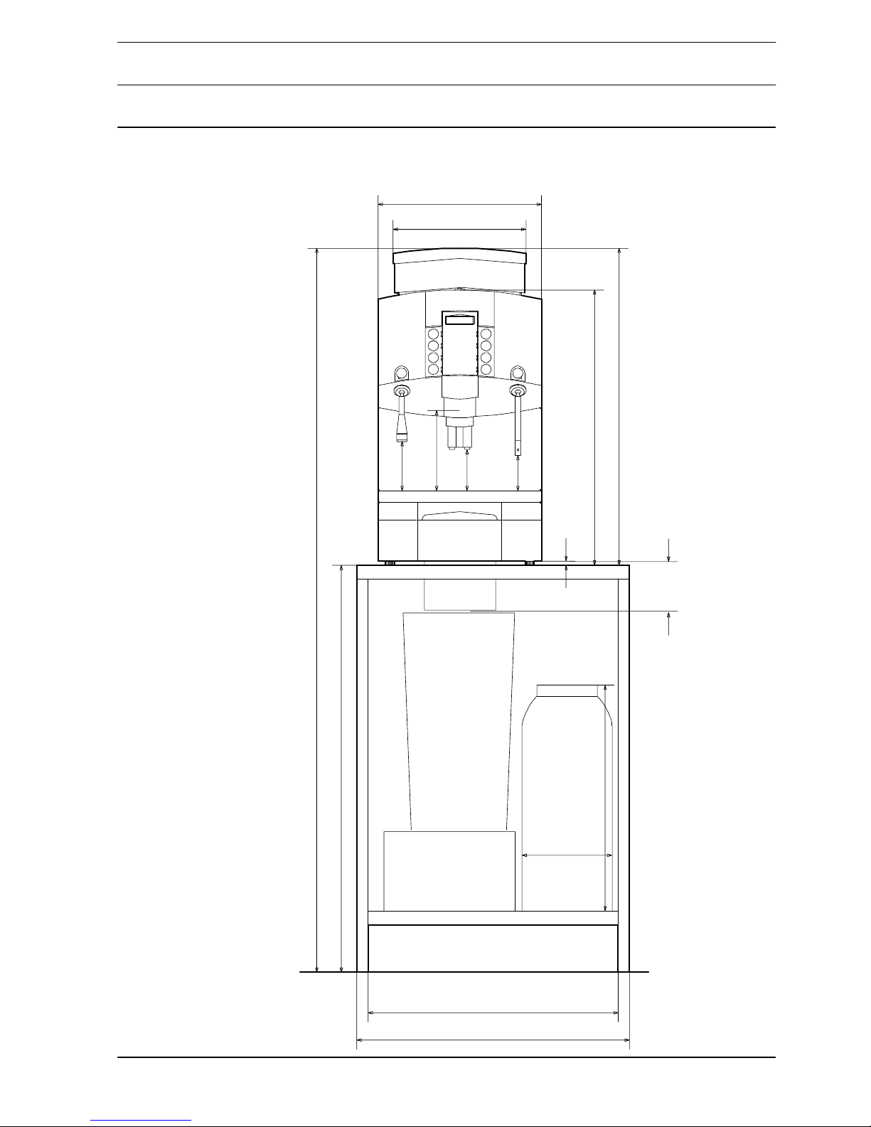
2. Dimensions, table cut−outs
2.1 Outer dimensions
Front view
Water
softener
Coffee
container
360
295
115
105
75
max.177
10
607
700
900
1600
500
220
560
600
ca.
130
ground
2-2
Service instructions bremer VIVA, issued 1997-07 Status: 2003-03
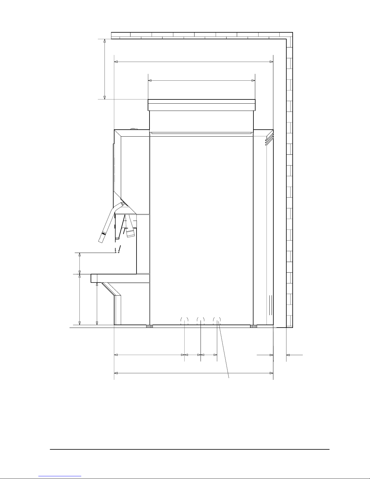
Side view
Cut−outs possible on both sides for
routing connections.
5050
min.70
40
min.200
221
130
155
490
330
497

2-3
Service instructions bremer VIVA, issued 1997-07 Status: 2003-03
2.2 Table cut−outs
Table cut−out
for water
inlet/outlet
pipes and
connecting
cable d=80
80
360
92
185
560
container ejection /
118 124
242
93 174
235
area
d=80 mm

3-1
Service instructions bremer VIVA, issued 1997-07 Status: 2003-03
3. Operating instructions
Operating instructions bremer VIVA in German, identity no.: 652067
Operating instructions “neutral” in English, identity no.: 668613
Operating instructions bremer VIVA in English, identity no.: 659800
Operating instructions bremer VIVA in Japanese, identity no.: 663204
Operating instructions bremer VIVA in French, identity no.: 684716
Operating instructions bremer VIVA in Netherland, identity no.: 690899
4-1
Service instructions bremer VIVA, issued 1997-07 Status: 2003-03
4. Adjustments prior to operation
4.1 Setting the coffee quality (till Software-Version 2.05)
See operating instructions for how to assemble and connect the machine.
Set the machine to the coffee quality required by the customer: coffee type, cof-
fee bean quanity, water quantity, etc.
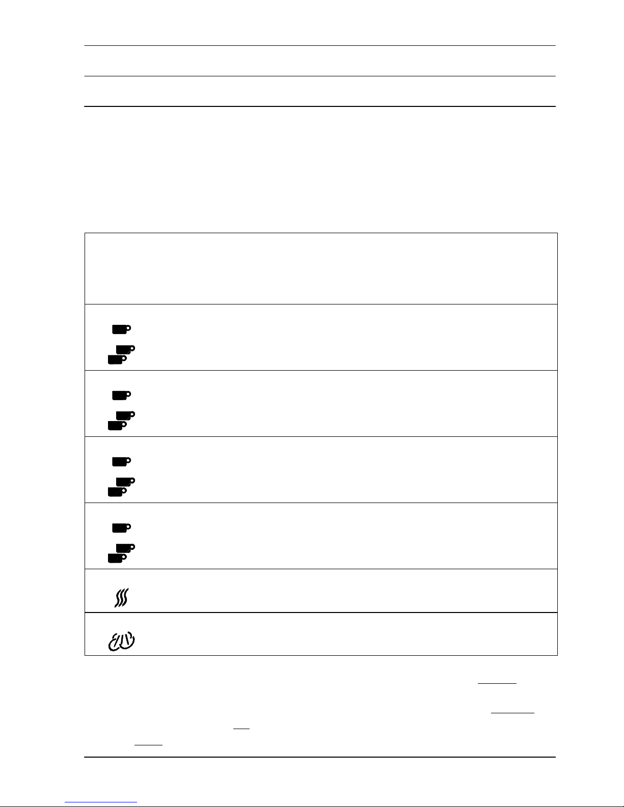
Standard factory setting for VIVA Standard (up to Vers. 2.05)
Article Grinder Ground
coffee
quantity
app.
1/100 s
Brewing
water
app 0,5
ml / imp.
Brewing
pres-
sure
Milk
froth
ON = Y7
open
Milk
dosage
Brewing
time
Grinder
locking
position
Coffee
centre 220 265 OFF ON 0 0 9
centre 380 530 OFF ON 0 0 9
Cafe Crème
right 220 240 ON ON 0 140 6
right 380 480 ON ON 0 200 6
Espresso
left 220 120 ON ON 0 100 6
left 380 240 ON ON 0 160 6
Cappuccino
left 220 200 ON ON 200 140 6
left 380 400 ON ON 300 200 6
Hot water
- - 100 - - - - -
Steam
- - - - - - - -
Brewing temperature: 93°C Hot water dispensing: metered / not−
metered
Capacity of grounds container: 100 tablets Dampfausgabe: dosiert / undosiert
Steam boiler available: YES / NO Pump pressure: 8 bar
Voltage: 230 V / 400 V

4-2
Service instructions bremer VIVA, issued 1997-07 Status: 2003-03
4.2 Standard settings (since Software-Version 3.02)
VIVA Standard factory setting with 3 coffee grinders (since Vers. 3.02)
Article Grin-
der
left
centre
right
Grinder
locking
position
0-14
Groun
d cof-
fee
quan-
tity
0-999
app.
1/100 s
Bre-
wing
water
0-999
app. 0,5
ml / imp.
Brewing
pres-
sure
OFF, ON
Bre-
wing
time
(only if
brewing
pres-
sure is
ON)
Milk
froth
0-999
Milk
do-
sage
0-999
Dosing
se-
quence
B=brewing
M=milk
MS= milk
foam
1, 2, 3,
0=Aus
Coffee B=1
M=0
MS=0
centre 12 170 265 OFF 0 0 0
centre 12 280 530 OFF 0 0 0
Cafe Crème B=1
M=0
MS=0
right 10 240 240 ON 140 0 0
right 10 380 480 ON 200 0 0
Espresso B=1
M=0
MS=0
left 10 240 120 ON 100 0 0
left 10 380 240 ON 160 0 0
Cappuccino B=1
M=0
MS=1
left 10 240 200 ON 140 200 0
White coffee B=1
M=1
MS=0
left 10 220 150 ON 100 0 90
Hot water
- - - 100 - - - - -
Brewing temperature: 93°C Hot water dispensing: metered / not−
metered
Capacity of grounds container: 100 tablets Dampfausgabe: dosiert / undosiert
Steam boiler available: YES / NO Pump pressure: 8 bar
old: Voltage: 230 V / 400 V
new: E1-E2 locked / unlocked
Pressure-reducing valve in the
equipment: 2.6 bar

4-3
Service instructions bremer VIVA, issued 1997-07 Status: 2003-03
VIVA Standard - Notes for customer’s settings
Article Grin-
der
left
centre
right
Grinder
locking
position
0-14
Groun
d cof-
fee
quan-
tity
0-999
app.
1/100 s
Bre-
wing
water
0-999
app 0,5
ml / imp.
Brewing
pres-
sure
OFF, ON
Bre-
wing
time
(only if
brewing
pres-
sure is
ON)
Milk
froth
0-999
Milk
do-
sage
0-999
Dosing
se-
quence
B=brewing
M=milk
MS= milk
foam
1, 2, 3,
0=Aus
Coffee
Cafe Crème
Espresso
Cappuccino
White coffee
Hot water
Brewing temperature: Pump pressure:
Grounds container capacity:
Steam boiler available:
Voltage / E1-E2 locked:
Hot water dispensing:
Customer: Coffee roaster:
4-4
Service instructions bremer VIVA, issued 1997-07 Status: 2003-03
VIVA au lait −without adjustable milk dosage −factory setting
Article Grin-
der
left
centre
right
Grin-
der
lok-
king
posi-
tion
0-14
Groun
d cof-
fee
quan-
tity
0-999
app.
1/100 s
Bre-
wing
water
0-999
app. 0,5
ml / imp.
Bre-
wing
pres-
sure
OFF, ON
Bre-
wing
time
(only if
brewing
pressure
is ON)
Milk
froth
0-999
Milk
do-
sage
0-999
Dosing
se-
quence
B=bre-
wing
M=milk
MS= milk
foam
1, 2, 3,
0=Aus
Coffee
centre 12 170 265 OFF 0 0 0
B=1
M=0
MS=0
Cafe Crème
right 10 240 240 ON 140 0 0
B=1
M=0
MS=0
Espresso
left 10 240 120 ON 100 0 0
B=1
M=0
MS=0
Latte
Macchiato
left 10 240 200 ON 140 200 0
B=3
M=1
MS=2
Cappuccino
left 10 240 200 ON 140 200 0
B=1
M=0
MS=1
White coffee
left 10 220 150 ON 100 0 90
B=1
M=1
MS=0
Espresso
Macchiato
left 10 240 120 ON 100 0 0
B=1
M=0
MS=2
Hot Milk
left 10 0 0 OFF 0 0 100
B=0
M=1
MS=0
Hot water
− − − 100 − − − − −
Brewing temperature: 93°C Hot water dispensing: metered / not−
metered
Capacity of grounds container: 100 tablets Dampfausgabe: dosiert / undosiert
Steam boiler available: YES / NO Pump pressure: 8 bar
old: Voltage: 230 V / 400 V
new: E1-E2 locked / unlocked
Pressure-reducing valve in the
equipment: 2.6 bar

4-5
Service instructions bremer VIVA, issued 1997-07 Status: 2003-03
VIVA au lait −without adjustable milk dosage −customer’s settings
Article Grin-
der
left
centre
right
Grin-
der
lok-
king
posi-
tion
0-14
Groun
d cof-
fee
quan-
tity
0-999
app.
1/100 s
Bre-
wing
water
0-999
app. 0,5
ml / imp.
Bre-
wing
pres-
sure
OFF, ON
Bre-
wing
time
(only if
brewing
pressure
is ON)
Milk
froth
0-999
Milk
do-
sage
0-999
Dosing
se-
quence
B=bre-
wing
M=milk
MS= milk
foam
1, 2, 3,
0=Aus
Coffee
Cafe Crème
Espresso
Latte
Macchiato
Cappuccino
White coffee
Espresso
Macchiato
Hot Milk
Hot water
Brewing temperature: Pump pressure:
Grounds container capacity:
Steam boiler available:
Voltage / E1-E2 locked:
Hot water dispensing:
Customer: Coffee roaster:
Table of contents
Other Bremer Coffee Maker manuals


