manuals.online logo
Brands
  1. Home
  2. •
  3. Brands
  4. •
  5. Brentwood
  6. •
  7. Lawn And Garden Equipment
  8. •
  9. Brentwood Wheelbarrow Single-Wheel Poly User manual

Brentwood Wheelbarrow Single-Wheel Poly User manual

Single- & Double-Wheel Poly
Wheelbarrow Assembly
STEP 1
Holding the PAN (A) on its side, use a hammer
to tap the four (4) 18 x 3"ELEVATOR BOLTS
(K) through the bottom and the two (2) 18 x 7/8"
ELEVATOR BOLTS (M) through the front so they
protrude facing outward. NOTE: Tapping the
bolts firmly in place allows them to penetrate the
poly pan and stay in place for Step 2. Next,
position the pan upside down so the bottom is
facing upward.
YOUR KIT SHOULD INCLUDE:
TOOLS NEEDED:
A. Pan (x1)
G. Leg (x2) H1. Single-Wheel Axle (x1)
H2. Double-Wheel Axle (x1)
J. Tire (x1)
Double-Wheel Models (x2)
I. Axle Bracket (x2)
F. Leg Brace (x1)
K. 5/16"- 18 x 3"
Elevator Bolt (x4)
P. 1/8"- 1.25"
Cotter Pin (x2)
Q. 3/4"
SAE Flat Washer (x2)
M. 5/16"- 18 x 7/8"
Elevator Bolt (x2)
L. 5/16"- 18 x 3"
Carriage Bolt (x6)
N. 5/16"- 18 x 3/4"
Slotted Truss Bolt (x4)
O. 5/16"- 18
Serrated Flange
Hex Nut (x16)
BL. Left Front Brace (x1) BR. Right Front Brace (x1) C. Handle (x2) D. Handle Grip (x2)
E. Nose Piece (x1)
A
K
K
K
K
M
M
Thank you for your purchase! If you have any questions or encounter any
problems with your Brentwood Wheelbarrow, feel free to call us at
1.610.374.5109 or e-mail wheelbarrow@brentw.com.
1. 1/2"or 13mm Wrench
2. Flat Head Screwdriver
3. Hammer
4. Needle Nose Pliers
5. Safety Glasses
STEP 3
Align the holes on the flat side of the LEG
BRACE (F) to the holes on the inside of each
leg and secure by hand tightening the
SLOTTED TRUSS BOLTS (N) and SERRATED
FLANGE HEX NUTS (O) into the four holes.
The bolt heads should face the rear of the
wheelbarrow. Next, place the NOSE PIECE (E)
onto the front of the handles with the flat side
facing forward. The portion with the holes
should be beneath the handles in its current
position; this will assure the nose piece is
mounted over the top and front sides of the
handle edges when upright. Next, secure the
nose piece by hand tightening two (2)
CARRIAGE BOLTS (L) and SERRATED
FLANGE HEX NUTS (O).
STEP 2
Slide the HANDLES (C) over the bolts installed
in the pan and be sure the logos are facing
upside down. Then, place the LEGS (G) over
the handles and align them to the existing
bolts. Secure them by hand tightening four (4)
SERRATED FLANGE HEX NUTS (O). NOTE:
Hand tightening bolts at this stage allows
flexibility throughout the assembly. Next, slide
the two (2) HAND GRIPS (D) onto the handles.
Finally, take the LEFT FRONT BRACE (BL) –
stamped with an “L” – and align it to the bolt
inserted in the hole at the front of the pan, also
stamped with an “L”. Repeat this step for the
RIGHT FRONT BRACE (BR), stamped with an
“R”, and secure the braces by hand tightening
two (2) SERRATED FLANGE HEX NUTS (O) to
the bolts. DO NOT attach the front braces to
the handles until Step 4.
STEP 4
Swing the left and right front braces to align
the free ends with the remaining holes in the
handles. Using the four (4) remaining
CARRIAGE BOLTS (L), insert each bolt from
the bottom up to secure the front braces,
handles, and two (2) AXLE BRACKETS (I).
Hand tighten using four (4) SERRATED
FLANGE HEX NUTS (O). The axle brackets
should allow for some flexibility at this stage of
the assembly.
O
G
O
O
GO
HANDLES ARE APPLIED
WITH LOGO FACING
UPSIDE DOWN
THE 2 HOLES LOCATED
ON THE LEGS SHOULD
FACE THE REAR OF THE
WHEELBARROW
HAND
TIGHTEN
BOLTS
HAND
TIGHTEN
BOLTS
O
O
O
O
O
O
I
I
E
D
D
C
C
HAND
TIGHTEN
BOLTS
O
O
O
O
L
LL
L
F
N
N
N
N
O
BR
BL
O
LEG BRACE SHOULD BE
INSTALLED SO ARCH FACES
UPWARD IN CURRENT POSITION
L
L
STEP 5 (DOUBLE WHEEL)
Slide the AXLE (H2) through the mounted axle
brackets and center. Then, on each side, slide
on a TIRE (J) and a SAE FLAT WASHER (Q).
Next, insert both COTTER PINS (P) through the
holes located on each end of the axle and
bend each end using needle nose pliers (FIG.
A). To secure the wheel assembly, push both
axle brackets outward and make sure all parts
are flush and aligned together (FIG. B). Finally,
firmly tighten all bolts in place using a hand
tool.
STEP 5 (SINGLE WHEEL)
When constructing the wheel assembly, an
additional person may be needed to hold the
tire in place. Slide the AXLE (H1) through the
mounted axle bracket. In this order, continue to
slide the axle through the first SAE FLAT
WASHER (Q), the TIRE (J), the second SAE
FLAT WASHER (Q), and finally, through the
second axle bracket (FIG. A). Next, insert both
COTTER PINS (P) through the holes located on
each of the axle brackets and bend each end
using needle nose pliers (FIG. B). To secure
the wheel assembly, push both axle brackets
inward to center the wheel and make sure all
parts are flush together (FIG. C). Finally, firmly
tighten all bolts in place using a hand tool.
J
H1
Q
Q
P
P
H2
Q
P
P
FIRMLY
TIGHTEN
ALL BOLTS
FIRMLY
TIGHTEN
ALL BOLTS
Q
J
J
IMPORTANT: Once you have completed the previous steps, be sure to tighten all bolts and
fastners using a hand tool. You are now ready to enjoy your Brentwood Wheelbarrow!
WHEEL ASSEMBLY DETAIL
CENTER
FIG. B FIG. C
FIG. A
WHEEL ASSEMBLY DETAIL
FIG. A FIG. B
CENTER
I I
Q Q
H1H1
J

This manual suits for next models

1

Popular Lawn And Garden Equipment manuals by other brands

Agria 1400 FARMBOY operating instructions

Agria

Agria 1400 FARMBOY operating instructions

Coopers of Stortford 10570 Instructions for use

Coopers of Stortford

Coopers of Stortford 10570 Instructions for use

Yard Machines F-49E Operator's manual

Yard Machines

Yard Machines F-49E Operator's manual

Mocka Foldable Trolley Assembly instructions

Mocka

Mocka Foldable Trolley Assembly instructions

Craftsman Incredi-Pull 316.794450 Operator's manual

Craftsman

Craftsman Incredi-Pull 316.794450 Operator's manual

Hozelock AQUA CONTROL 1 quick reference

Hozelock

Hozelock AQUA CONTROL 1 quick reference

Tiger TWR-120 parts manual

Tiger

Tiger TWR-120 parts manual

Husqvarna AUTOMOWER 105 Operator's manual

Husqvarna

Husqvarna AUTOMOWER 105 Operator's manual

Titan Tool Speeflo PowrLiner 6950 owner's manual

Titan Tool

Titan Tool Speeflo PowrLiner 6950 owner's manual

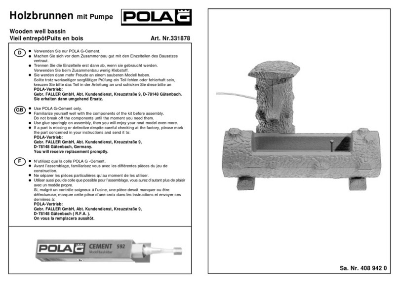
POLA G 331878 manual

POLA G

POLA G 331878 manual

Unkraut Fuchs FoXOne owner's manual

Unkraut Fuchs

Unkraut Fuchs FoXOne owner's manual

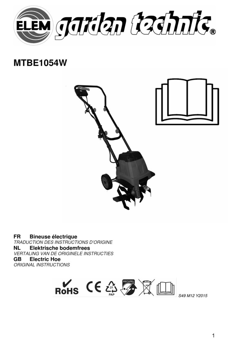
Elem Garden Technic MTBE1054W Original instructions

Elem Garden Technic

Elem Garden Technic MTBE1054W Original instructions

Oase AquaOxy 240 operating instructions

Oase

Oase AquaOxy 240 operating instructions

Kooper 5913686 User instructions

Kooper

Kooper 5913686 User instructions

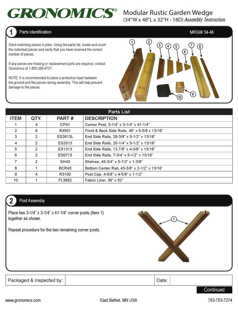
Gronomics MRGW 34-48 Assembly instruction

Gronomics

Gronomics MRGW 34-48 Assembly instruction

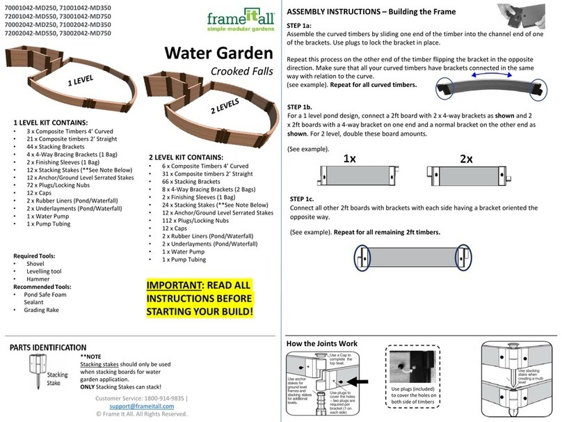
FRAME IT ALL Crooked Falls Assembly instructions

FRAME IT ALL

FRAME IT ALL Crooked Falls Assembly instructions

Duratuf KIWI MK3A Assembly instructions

Duratuf KIWI

Duratuf KIWI MK3A Assembly instructions

Teesa TSA0162 owner's manual

Teesa

Teesa TSA0162 owner's manual

manuals.online logo
manuals.online logoBrands
  • About & Mission
  • Contact us
  • Privacy Policy
  • Terms and Conditions

Copyright 2025 Manuals.Online. All Rights Reserved.