GB INSTRUCTION MANUAL
BR-CR1
Ceiling rail system
with pantographs
Art. No. F000224
GENERAL SAFETY INSTRUCTIONS
ATTENTION!
• The assembly must be carried out by a qualied tter! It is
recommended that two people carry out the assembly.
• The ceiling rail system may only be attached to ceilings with an
appropriate load-bearing capacity!
•
The structure of the ceiling must be suitably solid and suitable for
the subsequent total weight (including attached pantographs and
accessories). Never mount the ceiling rail system on a wooden ceiling
or an unstable or suspended ceiling!
• Always ensure that the mounting screws are properly anchored!
Note: Information on the weight of the ceiling rail system can be
found in the chapter "Technical data". The weight specications for
other possible add-on parts can be found in the operating instructions
supplied with these parts.
DANGER FROM FALLING OR DROOPING PARTS!
•
Make sure that the ceiling rail system is securely and stably mounted
before attaching other device accessories* to it.
• Secure all devices/accessories* mounted on the pantographs using
safety wire rope.
• Lay the voltage and connection cables in such a way that they cannot
be damaged by the trolleys or cause strangulation to persons!
• Only use accessories that meet the required specications. Find
more information in the chapter "Technical data".
• The maximum total load capacity of the ceiling rail system must
not be exceeded. At the maximum total load capacity, both the total
system weight and the weights of the mounted accessories/devices*
must be taken into account. Find detailed information on weights
under "Technical data" as well as in the manual of the mounted
accessory.
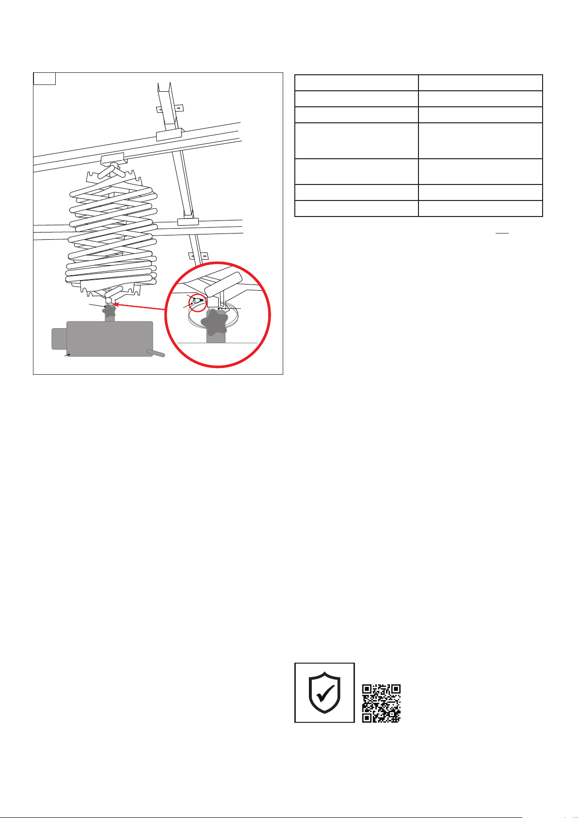
DANGER OF CRUSHING!
• Do not touch the guide rails during assembly, cleaning, operation
and when changing the position or moving the current collectors!
• Do not insert ngers into the lifting mechanism of the pantograph!
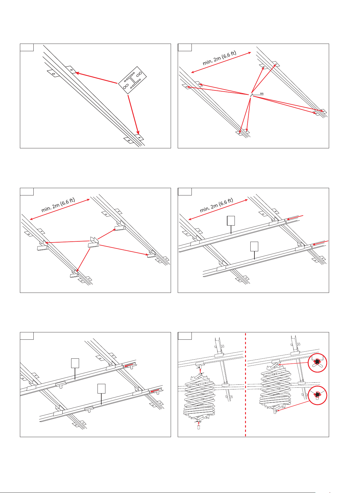
PARTS OVERVIEW (Fig. 1)
Single slide rails Double slide rails Ceiling brackets Double carriage roller Single carriage roller (with integrated spigot connection)
Pantograph Spigot adapter Rail stopper Safety wire rope Knob screw
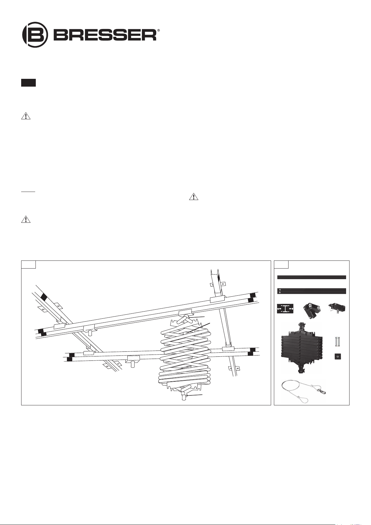
SCOPE OF DELIVERY (Fig. 2)
2x single slide rails 2x double slide rails Ceiling bracket (4x) Double carriage roller (4x) Single carriage roller (4x) Pantographs (4x)
Spigot adapter(4x) Rail stopper (12x) Safety wire rope (4x)
ADDITIONALLY REQUIRED*
Phillips screwdriver, 8 pcs. mounting screws (type M6) and, if necessary, suitable dowels/ceiling anchors for mounting the ceiling brackets
*not included with the purchase
Fig. 1 Fig. 2