manuals.online logo
Brands
  1. Home
  2. •
  3. Brands
  4. •
  5. Bresser
  6. •
  7. Telescope
  8. •
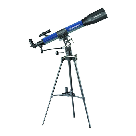
  9. Bresser First Light User manual

Bresser First Light User manual

Instruction manual
First Light
Refracting telescope
Art. No. 0115660
E
F
I
G
1(
1$
J
1%
1&
1#
1)
1^
h
B
c
Fig 1
http://www.bresser.de/download/0115660
Downloads:
• Astronomy Software
• Moon Map
• Instruction manual
1!
Fig 4
Fig 3
1@
1$
1%
1& 1)
J
Fig 1a
Z
W
X
Y
1(
2)
1*
Fig 2
2@
2!
1*
- 3 -
=
=
Fig 15
=
Fig 13
Y
=
Fig 5
X
=
Fig 9
X
=
Fig 8
B
L
E
J
H
b
F
C
D
K
=
Fig 6
1)
=
Fig 12
Fig 14 A.
B.
=
Fig 11
E
1@
=
Fig 7
1
X
G
A
4
8
8
=
=
Fig 10
X
Y
1(
1*
a
- 4 -
Fig 16 Fig 17
Fig 19
Fig 24
Fig 18
Fig 20 Fig 21
Fig 25
Fig 28
X
Y
X
Fig 22
J
C
X
Fig 29
X
Fig 27
X
Y2@
Fig 26
1*
1(
2!G
Fig 23
Z
1*
1(
2)
H
G
X
- 5 -
The moon
Orion Nebula (M 42)
Ring Nebula in the constellation "Lyra" (M 57)
Dumbbell Nebula in the constellation "Little Vixen" (lat. Vulpecula) (M 27)
f/20 mm
Fig 30 31
Fig 31 32
Fig 32 33
Fig 33 34
f/4 mm
Possible observation objects
- 6 -
General Information
About this Instruction Manual
Please read the safety instructions in this manual carefully. Use this product only
as described in the manual to avoid damage to the device or injury. Keep the
operating instructions in a safe place so that you can always keep up to date on
all the operating functions.
DANGER!
You will find this symbol before every section of text that
deals with the risk of minor to severe injuries resulting from
improper use.
ATTENTION!
You will find this symbol in front of every section of text which
deals with the risk of damage to property or the environment.
Designated use
This device is for personal use only.
It was developed for a magnified representation of observations of nature.
General warnings
RISK OF BLINDNESS!
Never look directly at, or near to the sun with this device. There is a RISK
OF BLINDNESS!
DANGER OF SUFFOCATION!
• Children must only use the device under adult supervision. Keep
packaging materials (plastic bags, rubber bands, etc.) away from child-
ren! There is a DANGER OF CHOKING!
FIRE HAZARD!
Do not expose this device - especially the lenses - to direct sunlight!
Focusing of sunlight could cause fires.
ATTENTION!
Do not disassemble the device! In the event of a defect, please contact
your dealer. They will contact the Service Center and can arrange the
return of this device for repair if necessary.
Do not expose the device to high temperatures.
Protect privacy!
The binoculars are intended only for private use. Respect the priva-
cy of your fellow human beings - do not look into private flats with
this device, for example!
All parts (Fig 1-3)
bTelescope tube
cLED viewfinder
dAdjustment screws
eTube opening
fObjective
gEyepiece socket
hFocus wheel (focus adjustment)
iTube clamp
jMounting
1) Accessories tray
1! Locking screws (tripod)
1@ Dust cap
1# Tripod Leg
1$ Flexible shaft for declination adjustment
1% Flexible shaft for rectascension adjustment
1^ Tripod spider
1& Counterweight + rod
1* Eyepiece
1( Upright Prism
2) Barlow Lens
2! T2-Adaptor M42 x 0,75mm*
2@ Smartphone Adaptor
*camera specific T2 ring additionally required, not included in the delivery
Parts (Fig15): Mounting
ATube clamp
BFocusing on the focus wheel
CScale of the declination-axis
DDeclination axis fixing screw
EFine-adjustment of the declination-axis
FLatitude setting scale
GFixing and adjusting screw of the latitude setting
HCounterweight with locking screw
IFixing screw of the right ascension axis
JRight ascension axis scale
KFine-adjustment of the rectascension-axis
LFixing screw for horizontal alignment
MBracket for optional tracking motor
NClutch for disengaging the engine
OTransmission gear for tracking motor
TIP:
The right ascension axis (Fig 16 green line) is also called the
hour axis.
The declination axis (Fig 16 blue line) is also called the
elevation axis.
i
Part I - The Structure
1. General information about the structure and the choice of location
Before you begin the assembly, you must choose a suitable location for your
telescope. It helps, if you set up this instrument in a location, where a clear view
of the skies, a stable footing and sufficient space around you are given.
First, remove all the parts from the packaging. Using the diagram, check whether
all the parts are included.
ATTENTION!
Only tighten the screws with care "hand-tight" to avoid
"overtightening" the screws. This can cause damage to the
screws and threads
2. Set up tripod
The tripod legs are pre-assembled and already connected to the tripod head (Fig
5, X) and the tripod spider (Fig 1, 16).
Remove the tripod from its packaging and place it vertically with the tripod feet
facing down. Now take two of the tripod legs and carefully pull these tripod legs
apart to the fully open position. The entire weight of the tripod rests on one leg.
Then set up the tripod straight.
Now pull out each tripod leg individually to the desired length (Fig 4) and now
turn one each of the clamping screws (Fig 4, 11) 3 pieces hand-tight. Do not
overtighten the screws! The clamping screws are used to lock the inner tripod leg
segments at the desired height.
TIP:
A small spirit level on the accessory tray can help you set up your
tripod level.
i
3. Insert mount
Next, attach the mount (Fig 1, 9) to the tripod head (Fig 5, X). To do this, insert
the mount into the top of the tripod head and hand-tighten the thumbscrew
from below.
The mount (Fig 1, 9) is assembled by sliding the weight on to the weight rod (Fig
7, X) and screwing it firmly in to the thread of the mount from below.
The mount is completed by placing the tube clamp (Fig 1+3, 8) on the mount and
securing it with the screw (Fig 8, X).
Maksutov optics do not have a tube clamp. The rail is placed directly on to the mount.
4. Mount shelf
The accessory tray (10) is placed on the tripod spider with the flat side down and
locked by turning the tray approx. 60° clockwise (Fig 6). The three pegs of the
tray should be centred in the receptacles of the tripod struts and snap into place.
5. Mounting the tube
To mount the telescopic tube (Fig 1, 1), first loosen the screws of the tube clamps
(Fig 9, X) on the holder and open the clamps.
- 7 -
Place the tube in the middle of the holder and close the clamps.
Hand-tighten the clamp screws again so that the tube is securely fastened in the
holder.
6. Insert eyepiece and upright prism
DANGER OF BLINDNESS!
Never look directly at, or near to the sun with this device.
There is a RISK OF BLINDNESS!
Two eyepieces (Fig 2, 18) and an upright prism (Fig 2, 19) are supplied with your
telescope as basic equipment.
With the eyepieces you determine the respective magnification of your tele-
scope.
Before inserting the eyepieces and the upright prism, remove the dust cap from
the eyepiece tube.
(Fig 1, 6) Loosen the clamping screw (Fig 12, X) on the eyepiece tube and insert
the upright prism first. Then retighten the clamping screw (Fig 12, X).
Then fix the 20mm eyepiece in the upright prism in the same way by opening
and closing the clamping screw (Fig 13a, X).
Make sure that the eyepiece sight points vertically upwards. This facilitates easy
viewing. Otherwise, loosen the clamping screw (Fig 12, X) on the eyepiece tube
and turn the upright prism to this position.
7. Mounting and adjusting the LED viewfinder
The LED viewfinder (Fig 1a, 2) and its holder form a single unit. Slide the base of
the LED viewfinder fully in to the corresponding base on the telescope tube (Fig
10, X) and then tighten the clamping screw (Fig 10, Y).
IMPORTANT: Make sure that the mirror surface of the LED viewfinder points
towards the tube opening when attaching it.
7.1. Battery replacement
Note: The battery of the LED viewfinder is protected against discharge by a
plastic foil when delivered. This must be removed before switching on for
the first time!
Press sideways on the battery insert marked "PUSH" (Fig 1a, W) so that it pops out
on the opposite side.
Insert the battery (button cell type CR2032, 3V) into the holder and slide the hol-
der back into the housing of the LED viewfinder.
8. Adjusting the LED viewfinder
The LED viewfinder must be adjusted before use. This means that the LED view-
finder and the telescope tube must be aligned in parallel.
Insert the eyepiece with the largest focal length into the upright prism (13). Aim
the telescope at a prominent object at a distance of approx. 300 m (e.g. house
gable, church spire, etc.) until it appears in the centre of the field of view (Fig14,
A).
Turn on the LED viewfinder. To do this, turn the front knurled screw (Fig 1a, Z)
until a soft click is heard.
If necessary, the brightness of the light spot can be adjusted by turning the knob
further.
Look through the LED viewfinder and adjust it by turning the horizontal (Fig
1a, X) and vertical (Fig 1a, Y) adjustment screws so that you see the red dot in
the center of the image (Fig14, C). The LED viewfinder and telescope are now
matched.
Important: The image in the telescope will be upside down unless you use
appropriate accessories to invert the image (e.g. zenith prism).
9. Use protective caps
To protect the inside of your telescope from dust and dirt, the tube opening is
protected by a dust cap (Fig 11, X). There is also a dust cap on the eyepiece tube
(Fig 1, 6).
10. Use flexible shafts
The flexible shafts facilitate the exact fine adjustment of the declination and right
ascension axis. They are pushed onto the holders provided for the two axles
(Fig13, Y) and fixed with the small clamping screws (Fig 13, X).
Note: The long flexible shaft (Fig 1, 14) is mounted parallel to the telescopic
tube. The fastening is done with a clamping screw at the provided notch
of the axle. The short flexible shaft (Fig 1, 15) is fitted laterally. The faste-
ning is done with a clamping screw at the provided notch of the axle.
The telescope is now ready for use.
PART II - The handling
1. Function and use of the mount
The following information is extremely important for the positioning and tra-
cking accuracy of your telescope during an observing night.
Your telescope has a so-called "parallactic mount" (also equatorial mount). This
is characterized by two axes that can be rotated perpendicular to each other
(Fig15, a+b)
The so-called right ascension axis (also RA or hour axis) (Fig 15, b) must be alig-
ned parallel to the polar axis of the earth (Fig 25, c). For the correct setting of the
pole height, see Part II - 4. Handling - Adjusting the telescope).
The declination axis (also DEC or elevation axis) (Fig15, a) is used to set the alti-
tude of a celestial object in relation to the celestial equator (Fig 25, d). To do this,
take the declination coordinate of a celestial object from a star chart or discover
the objects yourself.
With the manual operation of the right ascension axis via the flexible shaft (Fig
1, 15) you continuously compensate the earth rotation in the opposite direction.
This way, your selected (= positioned) object always remains in the field of view
of the eyepiece.
2. Choosing the right site
A dark location is very important for many observations, since disturbing lights
(lamps, lanterns) can considerably impair the sharpness of detail of the tele-
scope image.
When you go outdoors at night from a bright room, your eyes have to get used
to the darkness. After about 20 minutes you can start astro-observation.
Do not observe from closed rooms and place your telescope with the accessories
in its location approx. 30 min. before starting observation to ensure temperature
equalization in the tube.
Furthermore, you should make sure that this telescope is placed on a level, sta-
ble surface.
3. Balancing the telescope
Your telescope must be balanced before observing. That is, the declination axis
and the right ascension axis are adjusted for smooth and accurate operation.
The right ascension axis is balanced by loosening the fixing screw (Fig15, I) and
tilting the weight rod to a horizontal position. Now move the counterweight
(Fig15, H) on the rod until the tube and the counterweight remain in this horizon-
tal position. Retighten the fixing screw (Fig15, I) of the right ascension axis. The
declination axis is balanced by loosening the fixing screw (Fig15, D) of the dec-
lination axis. Then loosen the screws of the tube holder (Fig15, A) and move the
tube until it also remains in a horizontal position. Do not forget to re-tighten the
screws of the tube holder and the fixing screw of the declination axis.
4. Adjusting the telescope
Adjust the latitude axis (Fig15, F) (pole height) by loosening the fixing screw (Fig
17, X) and adjust the Pohl height accordingly with the adjusting screw (Fig 17, Y).
The number on which you set the axis depends on the latitude of your location
(e.g. Munich 48°, Hamburg 53°).
Do not forget to tighten the fixing screw again. Then adjust the declination axis
(Fig15, C) to 90° by loosening and tightening the fixing screw (Fig15, D). The
telescope tube is now aligned parallel to the Earth's axis. This is called polar
alignment.
TIP:
You will always find the latitude of your exact observation location
on the right or left edge of a map in an atlas. You can also obtain
information from your local council, land registry office or on the
Internet: e.g. at www.heavens-above.com. There you can select
your country under "Anonymous user > Select"; the data will then
be displayed.
i
5. Polar alignment of the telescope
Point the telescope with the tube opening forward towards the north. To do this,
loosen the locking screw (Fig 18). Now you can rotate the telescope tube and
align it exactly to the north. If necessary, use a compass to help you. Afterwards,
the locking screw is fixed again.
Check that your telescope is set up as shown in Fig 27. The counterweight (Fig
27, X) points to the ground and thus forms a vertical axis together with the tube.
In this position you can see the polar region with the polar star through the vie-
wfinder. Polaris is the brightest object in this region. (Fig 26)
- 8 -
This should then also be visible in the center of the field of view of the eyepi-
ece (f=20 mm). Polar alignment has been achieved. This setup requires some
patience, but rewards you with a good positioning option when searching with
celestial coordinates.
In this polar alignment, the graduated circles (scales) of the declination axis
(Fig 28) should be at "9" (= 90°) and the right ascension axis (Fig 29) at "0" (= 0
hours). If necessary, carefully rotate both scales to the appropriate values (alig-
ned with the arrows in each case).
Thus set, you can use the finding of celestial objects with the help of the gradua-
ted circles (scales) (see also 3.1. Possible objects of observation).
6. Fine alignment by means of LED viewfinder
Your telescope is now roughly aligned and adjusted.
To achieve a comfortable observation position, carefully loosen the screws of the
tube holder (Fig 9, X) so that you can rotate the telescope tube. Move the eyepie-
ce and LED viewfinder to a position from which you can observe comfortably.
The fine alignment is done by using the finder scope. Look through the viewfin-
der and try to align the polar star (Fig 26) with the illuminated point (Fig 14). The
shaft (Fig15, K) of the hour axis (Fig15, b), as well as the shaft (Fig15, E) of the
declination axis (Fig15, a) will help you with the exact setting.
7. First observations
Remove the caps from the openings for observation.
After you have adjusted the polar star in the LED viewfinder, you will be able to
see the polar star in the telescope when you now look through the eyepiece.
If necessary, you can now align the star more precisely with the aid of the
flexible shafts and adjust the focus using the focus wheel (7).
Furthermore, you can now set a higher magnification by changing the eyepiece
(smaller focal length). Please note that the magnification of the stars is hardly or
not at all perceptible.
TIP:
Eyepieces are lens systems that face the eye. With the eyepiece,
the image formed at the focal point of the telescope lens is recor-
ded, i.e. made visible, and magnified again. You need eyepieces
with different focal lengths to achieve different magnifications.
Start each observation with a low magnification eyepiece (= higher
focal length of 25mm).
i
8. Star search
At first, you will certainly find it difficult to orientate yourself in the starry sky, as
stars and constellations are always in motion and change their position in the
sky depending on the season, date and time.
The exception is the polar star. Through it runs the extended imaginary polar
axis of the earth. It is a fixed star and the starting point of all star charts. On the
drawing you can see some well-known constellations and star arrangements that
are visible all year round. However, the arrangement of the stars depends on the
date and time.
If you point your telescope at one of these stars, you will notice that it disap-
pears from the field of view of your eyepiece after a short time. To compensate
for this effect, operate the flexible shaft (Fig15, K) of the right ascension axis and
your telescope will follow the apparent trajectory of this star.
9. Setting circles
Stars and other heavenly bodies are positioned in the heavens by coordinates. A
star's place in the universe is determined by its right ascension and declination.
Declination (Fig 22, C) is the distance of a star from the celestial equator (Fig
25, d), measured in angular degrees. For stars north of the celestial equator,
the degree becomes positive. If the star is south of the equator, the degree is
marked with a minus sign.
Right ascension (Fig 22, J) is a distance of a star from the vernal equinox measured
on the celestial equator. The vernal equinox is the point of intersection of the
celestial equator with the apparent orbit of the sun (the so called Ecliptic) (Fig 25,
e). This happens in spring at the equinox (end of March). The value is counted in
time from 0 to 24 o'clock, contrary to the daily celestial revolution.
You can find more detailed information in star charts or the relevant specialist
literature.
10. Accessories
Several accessories (Fig 2) are supplied with your telescope as standard.
Important: When fitting accessories, ensure that the small clamping screws (Fig
12, X) for fixing are always hand-tightened.
10.1. Eyepieces
By changing the eyepieces, you determine the respective magnification of your
telescope.
Calculation of the magnification:
Focal length (telescope) ÷ Focal length (eyepiece) = Magnification
Examples:
Telescope’s
focal length
Eyepiece’s
focal length
Magnication Magnication
with 3x Barlow lens
1000 mm 25 mm 40X 120X)
1000 mm 10 mm 100X 300X
10.2. Upright Prism
The upright prism produces an upright and laterally correct field of view and is
therefore particularly suitable for earth observation. But it is also very helpful for
easier orientation in the starry sky.
10.3. Barlow Lenses
With a 3x Barlow lens, you can achieve an additional increase in magnification
of 3x.
If necessary, the Barlow lens (Fig 23, 20) is inserted between the upright prism
(Fig 23, 19) and the eyepiece (Fig 23, 18).
10.4. Adaptor:
With the T2 adaptor you create the basis for the attachment of a photo camera
with T2 connection (lens connection).
To use the T2 adapter, first unscrew the retaining ring from the eyepiece tube
(Fig 21, 6). Then screw on the T2 adapter (Fig 21, 21) in its place.
In order to mount a photo camera, an additional camera-specific T2 ring is requi-
red, which is screwed between the camera and the T2 adapter.
10.5. Smartphone Adaptor
Insert the eyepiece into the smartphone holder and tighten the screw (Fig 24,
X) on the holder firmly. Then insert the smartphone holder with the eyepiece
into the eyepiece socket (6) or the upright prism (19) (refracting telescopes) and
hand-tighten the clamping screws (Fig 24, Y) on the socket or upright prism.
Now launch the camera app from your smartphone. Now press your smartphone
onto the holding plate and make sure it is properly attached. The camera must
be positioned exactly above the eyepiece. Centre the smartphone exactly over
the eyepiece so that the image is exactly centred on your display. It may be
necessary to use the zoom function to fill the image on the display. The suction
cups must be dry, clean and free from all types of dust and dirt. We do not take
responsibility for dropped and broken smartphones due to incorrect operation.
11. Dismantling
After a hopefully interesting and successful observation it is recommended to
store the entire telescope in a dry and well ventilated room. Some telescope
models allow you to separate the mount and tripod by simply unscrewing them.
In this case, your settings on the mount are retained. Do not forget to put the
dust-protection-caps on to the OTA opening and on to the eyepiece connection.
Also, you should stow all the eyepieces and optical accessories into their corres-
ponding containers.
12. Cleaning & Storage
Clean the lenses (eyepieces and/or objective lenses) only with a soft and lint-free
cloth (e.g. microfibre cloth). To avoid scratching the lenses, use only gentle pres-
sure with the cleaning cloth.
To remove more stubborn dirt, moisten the cleaning cloth with an eyeglass-
cleaning solution and wipe the lenses gently.
Protect the device from dust and moisture! After use, particularly in high humi-
dity, let the device acclimatise at room temperature for a short period of time, so
that the residual moisture can dissipate.
- 9 -
PART III - Appendix
1. Possible observation objects
Below we have selected and explained some very interesting celestial bodies and
star clusters. In the accompanying illustrations at the end of the manual you can
see how you will see the objects through your telescope with the supplied eyepi-
eces in good viewing conditions:
Moon (Fig 30)
The moon is the only natural satellite of the earth
Orbit: approx. 384,400 km from the earth
Diametre: 3.476 km
Distance: 384.401 km
The moon has been known since prehistoric times. It is the second brightest
object in the sky after the sun. As the moon orbits the earth once a month, the
angle between the earth, the moon and the sun is constantly changing; you can
see this in the cycles of the moon's phases. The time between two consecutive
new moon phases is about 29.5 days (709 hours).
Constellation ORION / M42 (Fig 31)
Right Ascension (R.A): 05:32.9 (hours : minutes)
Declination (DEC): 05:25 (degrees : minutes)
Distance: 1.500 million light years
At a distance of about 1600 light-years, the Orion Nebula (M42) is the brightest
diffuse nebula in the sky - visible to the naked eye, and a rewarding object for
telescopes of all sizes, from the smallest binoculars to the largest Earth-based
observatories and the Hubble Space Telescope.
It is the main part of a much larger cloud of hydrogen gas and dust, extending
at more than 10 degrees over well over half of the constellation of Orion. The
extent of this enormous cloud is several hundred light years.
Constellation LEIER / M57 (Fig 32)
Right ascension: 18:51.7 (hours : minutes)
Declination (DEC): 32:58 (degrees : minutes)
Distance: 4.100 million light years
The famous Ring Nebula M57 in the constellation Lyra is often considered the pro-
totype of a planetary nebula; it is one of the splendors of the northern hemisphere
summer sky. Recent studies have shown that it is most likely a ring (torus) of brightly
glowing matter surrounding the central star (visible only with larger telescopes),
rather than a spherical or ellipsoidal gas structure. If the Ring Nebula were viewed
from the side plane, it would resemble the Dumbell Nebula M27. We are looking
right at the pole of the nebula for this object.
Constellation Vixen / M27 (Fig 33)
Right Ascension (R.A): 19:59.6 (hours : minutes)
Declination (DEC): 22:43 (degrees : minutes)
Distance: 1.250 million light years
The Dumbbell Nebula M27 or Dumbbell Nebula in the Vixen was the first pla-
netary nebula ever discovered. On July 12, 1764, Charles Messier discovered
this new and fascinating class of objects. We see this object almost exactly from
its equatorial plane. If the Dumbell Nebula were seen from one of the poles, it
would probably have the shape of a ring and resemble the sight we know from
the Ring Nebula M57. This object can already be seen well in halfway good wea-
ther conditions at low magnifications.
2. Troubleshooting
Mistakes: Solution:
No image Remove dust cap from tube opening
Select eyepiece with lower magnification (= high-
er focal length)
Blurred picture Focusing on the focus wheel
No focusing possible Wait for temperature equalization (approx. 30
minutes)
Bad picture Never watch through a pane of glass
Observation object in the
viewfinder, but not visible
through the eyepiece
Adjust the viewfinder (see Part I - 8.)
Difficult tracking of the
axes via shafts
Balance telescope and counterweight (sh. Part
II - 3.)
Despite upright prism only
"crooked" image
Align upright prism vertically in the eyepiece
tube
Disposal
Dispose of the packaging materials by type. Contact your local waste-dispo-
sal service or environmental authority for information on the proper dispo-
sal.
Observe the current legal regulations when disposing of the device!
Information on proper disposal can be obtained from municipal waste dis-
posal service providers or the Environmental Agency.
Do not dispose of electronic devices in the household waste!
According to the European Directive 2002/96/EC on Waste Electrical and
Electronic Equipment and its transposition into national law, used electrical
equipment must be collected separately and recycled in an environmentally sound
manner.
Batteries and rechargeable batteries must not be disposed of with household
waste. You are legally obliged to return used batteries and accumulators and
can return the batteries after use either in our sales outlet or in the immediate
vicinity (e.g. in the trade or in municipal collection points) free of charge.
Batteries and accumulators are marked with a crossed-out dustbin and the che-
mical symbol of the pollutant, "Cd" stands for cadmium, "Hg" stands for mercury
and "Pb" stands for lead.
Warranty & Service
The regular warranty period is 5 years and begins on the day of purchase. For
complete warranty terms and services, please visit www.bresser.de/warran-
ty_terms.
In the event of a warranty claim, please first contact the service team responsible
for your country, preferably by e-mail or using the contact form on the website.
Here you can be helped quickly in most cases. The corresponding contact informa-
tion can be found under "Service" in this manual.
IMPORTANT!
Do not send in devices - even in the event of damage - without first consul-
ting the service department. Unfortunately, unsolicited devices cannot be
accepted and processed.
- 10 -
DE
AT
CH
BE
Bei Fragen zum Produkt und eventuellen
Reklamationen nehmen Sie bitte zunächst mit
dem Service-Center Kontakt auf, vorzugsweise
per E-Mail.
E-Mail: [email protected]
Telefon*: +4928728074210
BRESSER GmbH
Kundenservice
Gutenbergstr. 2
46414 Rhede
Deutschland
*Lokale Rufnummer in Deutschland (Die Höhe der Gebühren je
Telefonat ist abhängig vom Tarif Ihres Telefonanbieters); Anrufe aus
dem Ausland sind mit höheren Kosten verbunden.
GB
IE
Please contact the service centre fi rst for any
questions regarding the product or claims,
preferably by e-mail.
E-Mail: [email protected]
Telephone*: +441342837098
BRESSER UK Ltd.
Suite 3G, Eden House
Enterprise Way
Edenbridge, Kent TN8 6HF
United Kingdom
*Number charged at local rates in the UK (the amount you will
be charged per phone call will depend on the tariff of your phone
provider); calls from abroad will involve higher costs.
FR
BE
Si vous avez des questions concernant ce produit
ou en cas de réclamations, veuillez prendre
contact avec notre centre de services (de
préférence via e-mail).
E-Mail: [email protected]
Téléphone*: 00 800 6343 7000
BRESSER France SARL
Pôle d’Activités de Nicopolis
314 Avenue des Chênes Verts
83170 Brignoles
France
*Prix d'un appel local depuis la France ou Belgique
NL
BE
Als u met betrekking tot het product vragen
of eventuele klachten heeft kunt u contact
opnemen met het service centrum (bij voorkeur
per e-mail).
E-Mail: [email protected]
Telefoon*: +31528232476
BRESSER Benelux
Smirnoffstraat 8
7903 AX Hoogeveen
The Netherlands
*Het telefoonnummer wordt in het Nederland tegen lokaal tarief
in rekening gebracht. Het bedrag dat u per gesprek in rekening
gebracht zal worden, is afhankelijk van het tarief van uw telefoon
provider; gesprekken vanuit het buitenland zullen hogere kosten met
zich meebrengen.
ES
IT
PT
Si desea formular alguna pregunta sobre el
producto o alguna eventual reclamación, le
rogamos que se ponga en contacto con el centro
de servicio técnico (de preferencia por e-mail).
E-Mail: [email protected]
Teléfono*: +34 91 67972 69
BRESSER Iberia SLU
c/Valdemorillo,1 Nave B
P.I. Ventorro del Cano
28925 Alcorcón Madrid
España
*Número local de España (el importe de cada llamada telefónica
dependen de las tarifas de los distribuidores); Las llamadas des del
extranjero están ligadas a costes suplementarios..
Service
- 11 -
Notes
Bresser GmbH
Gutenbergstraße 2
46414 Rhede · Germany
www.bresser.de
@BresserEurope
© 2021 Bresser GmbH, 46414 Rhede, Germany.
No part of this manual may be reproduced, transmitted, transcribed or translated into any langua-
ge in any form without the written permission of Bresser GmbH.
Errors and technical changes reserved.
Manual_0115660_First-Light-Telescope_en_BRESSER_v012021a

This manual suits for next models

1

Other Bresser Telescope manuals

Bresser AR-90 User manual

Bresser

Bresser AR-90 User manual

Bresser 43-34000 User manual

Bresser

Bresser 43-34000 User manual

Bresser SKYLUX 60/700 AZ User manual

Bresser

Bresser SKYLUX 60/700 AZ User manual

Bresser DOB-203 User manual

Bresser

Bresser DOB-203 User manual

Bresser LUNT CAA-RF User manual

Bresser

Bresser LUNT CAA-RF User manual

Bresser 90-57000 User manual

Bresser

Bresser 90-57000 User manual

Bresser NATIONAL GEOGRAPHIC Adventurer User manual

Bresser

Bresser NATIONAL GEOGRAPHIC Adventurer User manual

Bresser 80/400 User manual

Bresser

Bresser 80/400 User manual

Bresser National Geographic 9062000 User manual

Bresser

Bresser National Geographic 9062000 User manual

Bresser National Geographic 91-06000 User manual

Bresser

Bresser National Geographic 91-06000 User manual

Bresser 70/900 NG User manual

Bresser

Bresser 70/900 NG User manual

Bresser 8" Messier Dobson User manual

Bresser

Bresser 8" Messier Dobson User manual

Bresser TRAVEL User manual

Bresser

Bresser TRAVEL User manual

Bresser Messier User manual

Bresser

Bresser Messier User manual

Bresser Skylux 70/700 User manual

Bresser

Bresser Skylux 70/700 User manual

Bresser National Geographic 76/350 User manual

Bresser

Bresser National Geographic 76/350 User manual

Bresser SpaceExplorer MC 127/1900 EQ User manual

Bresser

Bresser SpaceExplorer MC 127/1900 EQ User manual

Bresser 12x30 Stoertebeker User manual

Bresser

Bresser 12x30 Stoertebeker User manual

Bresser Venus 45-41000 User manual

Bresser

Bresser Venus 45-41000 User manual

Bresser Spotty 20-60x60 User manual

Bresser

Bresser Spotty 20-60x60 User manual

Bresser DOB-150 Programming manual

Bresser

Bresser DOB-150 Programming manual

Bresser JUNIOR 45/600 AZ User manual

Bresser

Bresser JUNIOR 45/600 AZ User manual

Bresser SKYLUX 60/700 AZ User manual

Bresser

Bresser SKYLUX 60/700 AZ User manual

Bresser 60/700 User manual

Bresser

Bresser 60/700 User manual

Popular Telescope manuals by other brands

Celestron 21070 instruction manual

Celestron

Celestron 21070 instruction manual

Bushnell NORTH STAR GOTO 78-8840 instruction manual

Bushnell

Bushnell NORTH STAR GOTO 78-8840 instruction manual

Meade LX70 Series instruction manual

Meade

Meade LX70 Series instruction manual

Orbitor C90T user guide

Orbitor

Orbitor C90T user guide

Meade 102ED instruction manual

Meade

Meade 102ED instruction manual

Zhumell Dobsonian user guide

Zhumell

Zhumell Dobsonian user guide

Hobym Observatory Crux140 Traveler user manual

Hobym Observatory

Hobym Observatory Crux140 Traveler user manual

ASTRO-PHYSICS 400 manual

ASTRO-PHYSICS

ASTRO-PHYSICS 400 manual

William Optics Synta Crayford user guide

William Optics

William Optics Synta Crayford user guide

Vixen GP-DX instruction manual

Vixen

Vixen GP-DX instruction manual

Minox Macroskop MS 8x25 Product information

Minox

Minox Macroskop MS 8x25 Product information

Minox MD 62 ED brochure

Minox

Minox MD 62 ED brochure

Celestron Regal M2 instruction manual

Celestron

Celestron Regal M2 instruction manual

Levenhuk Strike 100 PLUS user manual

Levenhuk

Levenhuk Strike 100 PLUS user manual

Celestron CPC Series instruction manual

Celestron

Celestron CPC Series instruction manual

Meade 6600 operating instructions

Meade

Meade 6600 operating instructions

ORION TELESCOPES & BINOCULARS SkyQuest XT10 9810 instruction manual

ORION TELESCOPES & BINOCULARS

ORION TELESCOPES & BINOCULARS SkyQuest XT10 9810 instruction manual

Bushnell Trophy 78-7325 user guide

Bushnell

Bushnell Trophy 78-7325 user guide

manuals.online logo
manuals.online logoBrands
  • About & Mission
  • Contact us
  • Privacy Policy
  • Terms and Conditions

Copyright 2025 Manuals.Online. All Rights Reserved.