brewer 9000 series User manual

Document 99958 rev B
© October 2016
Important Information............................................2
Safety Information.................................................2
Specifications........................................................2
Stool Components.................................................3
Cleaning................................................................3
Assembly Instructions...........................................4
Stool Adjustments .................................................5
Operation ..............................................................6
Maintenance..........................................................7
Accessories & Service Parts.................................7
Troubleshooting.....................................................8
9000, 9100, 9200, and 9500 Series
User Manual
The Brewer Company, LLC
N88 W13901 Main Street, Suite 100
Menomonee Falls, WI 53051
P 1.888.Brewer.1
F 262.251.2332
www.brewercompany.com
Premium Ergonomic Seating

Document 99958 rev B© October 2016 2
IMPORTANT INFORMATION
General
The Brewer 9X00 Series stools offer Brewer’s clinically researched ergonomic seating. The variety of seat and back options offer
superior lumbar support, allow for proper weight distribution, encourage neutral posture, and promote muscular health.
Intended Users
The stools are intended to provide seated support for members of the dental team during treatment of dental patients by licensed
health care professionals. The stools are for professional use only.
SAFETY INFORMATION
Service
If you require assistance with the assembly or operation
of your Brewer stool, call Brewer Customer Service at
888-Brewer-1. Our trained staff will attempt to assist you
in correcting the problem directly over the phone. If service
is required, please contact your local equipment dealer.
Please have the following information from the product
label located under the seat before calling Brewer or your
distributor with questions regarding your unit.
SPECIFICATIONS
Safety Information
The primary concern of The Brewer Company is that the stool is operated and maintained with the safety of the patient
and health care staff in mind. To ensure safe and reliable operation:
•Read and understand all instructions in this manual before attempting to assemble or operate the unit.
•Ensure that appropriate personnel are informed on the manual contents. This is the responsibility of the purchaser.
•Ensure that this manual is located near the stool.
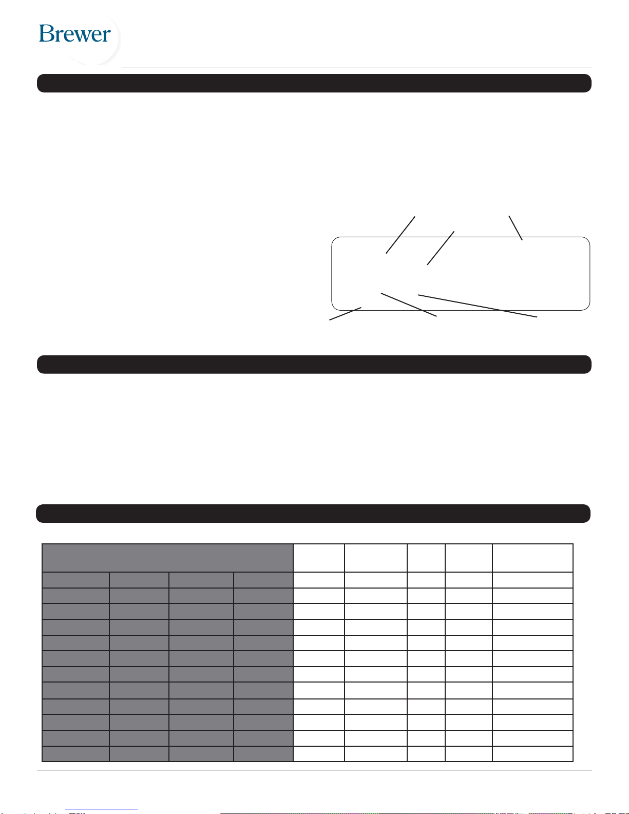
XXXXXXX
STOOL, XXXXXXX
XXXXXX-XXXXXXXXXX
XXXXXXX
Brewer Day-Month-Year
Model number
Upholstery color
Order number
Description
Manufacture date
Upholstery code
Part Numbers Model Seamless
Upholstery Foot
Ring Body
Support Height Range
(assembled)
9000BST 9100B 9200BST 9500B Operator No No No 18.5”–24.5”
9000BFRST 9100BFR 9200BFRST 9500BFR Operator No Yes No 22”–31”
9000B 9100BV 9200B 9500BV Operator Yes No No 18.5”–24.5”
9000BFR 9100BVFR 9200BFR 9500BVFR Operator Yes Yes No 22”–31”
9000BST-L 9100B-L 9200BST-L 9500B-L Operator No No No 15.5”–20”
9000B-L 9100BV-L 9200BL 9500BV-L Operator Yes No No 15.5”–20”
9000BST-H 9100B-H 9200BST-H 9500B-H Operator No No No 20.5”–26.5”
9000B-H 9100BV-H 9200B-H 9500BV-H Operator Yes No No 20.5”–26.5”
9020BLST 9120BL 9220BLST 9520BL Assistant No Yes Left 24”–32”
9020BL 9120BLV 9220BL 9520BLV Assistant Yes Yes Left 24”–32”
9020BRST 9120BR 9220BLST 9520BR Assistant No Yes Right 24”–32”
9020BR 9120BRV 9220BR 9520BRV Assistant Yes Yes Right 24”–32”
All Brewer 9X00 Series stools have a 25” base diameter and a 250 lb. weight capacity.

Document 99958 rev B© October 2016 3
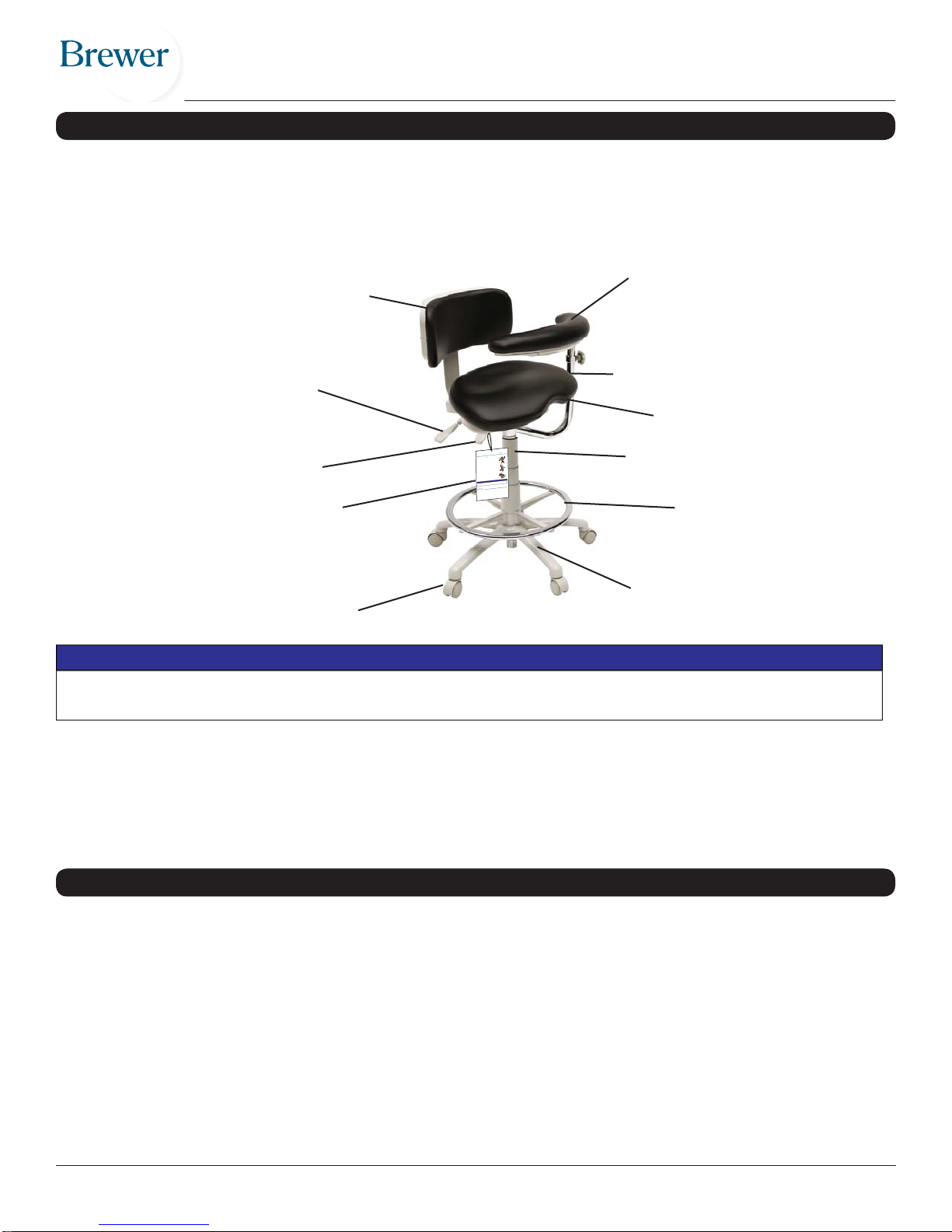
STOOL COMPONENTS
Seat-Back Tilt Lever
Quick Start Tag
The Brewer 9X00 Series Stools utilize clinically researched ergonomic designs to ensure proper working posture, com-
fort, and adjustability.
Note: Make sure that the following components are included and that the stool operates properly before discarding
packaging materials. The images in this user manual may show a footring and a body support, but not all models are
equipped with these features. Also, the backrest may have a different shape.
Pneumatic Cylinder
Seat Assembly (upholstered
seat with control plate)
Caster Base
Casters (5)
To avoid damaging the stool’s upholstery, do not use a knife or other sharp object to open the package. Also,
to avoid damaging the stool do not use height adjustment lever for lifting.
NOTICE
www.brewercompany.com 1.888.273.9371
Using the 135DSS Dynamic Saddle Stool
1. Always approach the stool from the
backand stand to one side.
2. Swing other leg over the back of the
stooland be seated.
3. Lift the adjustment lever until feet are
ÀDWEXWMXVWWRXFKLQJWKHÀRRU
4. Knees should angle downward at
approximately 135
o
. The stool is now
atyour proper ergonomic height.
5. Adjust work surface so the user’s
IRUHDUPVDUHLQ D KRUL]RQWDO SRVLWLRQ
or sloping downward at a maximum
of3
o
-4
o
.
o
Newusers to the 135DSS Stool should expect some discomfort
ZLWKLQWKH¿UVWIHZGD\VDVWKHERG\JHWVXVHGWRWKLVQHZSRVWXUH
NOTICE
6LWWLQJRQWKH'666WRRO
135
o
Using the
he 135DSS Dyn
amic Sadd
ddl
ool from the
6LWWLQJRQWKH'666WRRO
'666WRRO
Backrest Body Support
Footring
Seat Height Lever
Back Tilt Lever
(9500 Series only)
CLEANING
Please see the Brewer Cleaning Guidelines in the “Resources” area of www.brewercompany.com.

Document 99958 rev B© October 2016 4
1. Remove the body support (if equipped), the backrest, and the stool from the box, and set aside (Fig. 1 and 2).
ASSEMBLY INSTRUCTIONS
Fig. 3 Fig. 4
Fig. 1 Fig. 2
2. On the backrest, remove the screws and lock washers from the holes at the bottom of
the backrest (Fig. 3). Slide the shroud toward the center of the seat. Place the back-
rest bottom into the seat slot located at the rear of the seat. Match up the holes in the
slot with the holes in the backrest bottom. Insert the two bottom screws through the
lock washers into the holes, but do not tighten. Next, install the top screw, and tighten
with a Phillips screwdriver (Fig. 4). Finally, tighten the bottom two screws.
3. If your stool has a body support, swing it to the correct side of the stool for your ap-
plication (i.e. left or right side of stool), and insert the body support into the swing arm
(Fig. 5). The knob can be positioned in three different directions, forward, backward,
or outward.
Fig. 5
4. If you also purchased armrests, these can be inserted into the arm tabs on either side of the control plate. Tighten the
knobs under the arm tabs to secure the armrests.

Document 99958 rev B© October 2016 5
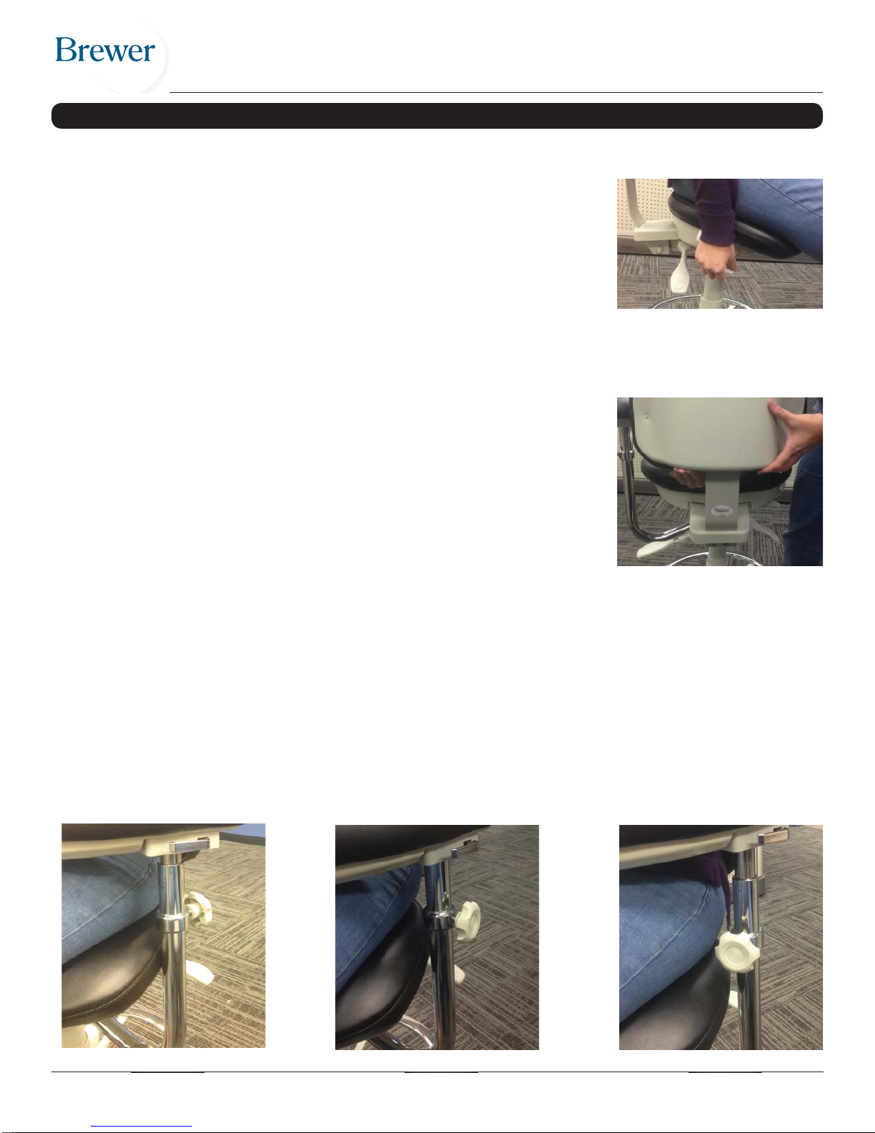
STOOL ADJUSTMENTS
Back Height
Grasp the lower edge of the backrest and lift it as far as it will go to disengage the
height locking mechanism (Fig.7). Next, lower the backrest as far as it will go to reset
the height locking mechanism. Finally, lift the backrest to the height desired.
For maximum comfort, the backrest should be positioned firmly against the lumbar
region of your back. The backrest has eight heights to which it can be set.
Body Support Height (if equipped)
The body support has a lock collar and knob which may be placed in any one of three positions (Fig. 8, 9, and 10). To
adjust the lock collar and knob into a new position:
1. Loosen the body support knob until the lock collar moves freely on the swing arm. Do not completely remove the
knob from the lock collar.
2. Reposition the lock collar and knob to the new position, and tighten the knob just enough to hold the lock collar in
place.
3. Install the body support post into the swingarm with the channel of the post aligned with the threaded end of the
knob.
4. Tighten the knob to secure the body support.
Seat Height
To adjust the seat height downward, sit on the chair and lift the lever under the seat
side edge (Fig. 6). To raise the seat height, remove your weight from the seat and lift
the lever under the seat side edge. Release the lever at the desired seat height.
For maximum comfort, your chair seat should be adjusted so that your hands rest
comfortably on your work surface. Your feet should be flat on the floor with the inside
angle of the knee joint being slightly more than 90 degrees, and you should feel no
pressure underneath your thighs. Fig. 6
Fig. 7
Fig. 8 Fig. 9 Fig. 10

Document 99958 rev B© October 2016 6
STOOL ADJUSTMENTS
Back Tilt (9500 Series only)
Lift and hold the back left lever to release the backrest from its locked position (Fig.
11). Adjust the backrest angle by bending your back in the desired direction. Push the
paddle down to lock. If you prefer, the backrest can remain unlocked by leaving the
paddle up.
Locking Seat-Back Tilt & Angle (9000, 9100, and 9200 Series only)
Lift and hold the back right lever to release both the seat and backrest from their
locked position (Fig. 12). Shift your body weight to adjust the seat angle, and then
adjust the backrest angle by bending your back in the desired direction. Push the
paddle down to lock. If you prefer, the seat and backrest can remain unlocked by
leaving the paddle up.
Locking Seat-Back Tilt & Angle (9500 Series only)
Lift and hold the back right lever to release the seat and backrest from their locked
position (Fig. 12). The seat and back will tilt forward and backward together. Push
the paddle down to lock in the desired tilt position. If you prefer, the seat can remain
unlocked by leaving the paddle up.
Alternately, by lifting and holding the back left tilt lever while the back right lever is
unlocked, you can adjust the angle between the seat and the back.
Footring Height (if equipped)
Loosen the knob on the footring, raise or lower the footring to the desired height, and
tighten the knob (Fig. 13).
Fig. 11
Fig. 12
Fig. 13
OPERATION
Body Support (if equipped)
The body support ratchets inward by grasping the free
end and pulling it toward the body when seated. The body
support automatically locks in the chosen body position.
To release the rotational lock on the body support, remove all
body weight from the body support, and pull inward on lever
(Fig. 14). While holding the lever, rotate the body support
outward to exit the chair.
Fig. 14

Document 99958 rev B© October 2016 7
MAINTENANCE
Seat Screws
Periodically check seat screws (Fig. 15) for tightness. Tighten with Phillips
screwdriver if loose.
Casters
Inspect casters for cracked, chipped, loose or missing wheels. Casters should roll
freely. Note: Optional non-pressure locking casters must have weight applied
to roll. Replace if damaged.
Caster Base
Inspect caster base for cracks or other damage. Replace if damaged.
Cylinder
Cylinder defects are indicated by; the seat rising on its own, drifting downward, or failure to raise or lower with height
adjustment lever. See “TROUBLESHOOTING” section for diagnosis.
Seat
Inspect seat unit for cracks or damaged height adjustment lever. Replace if damaged. See “TROUBLESHOOTING”
section for diagnosis. What may appear to be damage may be a needed adjustment.
Fig. 15
ACCESSORIES & SERVICE PARTS
Upholstered Seats
90X0/92X0 Upholstered Seat Pad..............................................................................................................................3102363
90X0/92X0 Upholstered Seat Pad (seamless)...........................................................................................................3102362
91X0 Upholstered Seat Pad.......................................................................................................................................3102365
91X0 Upholstered Seat Pad (seamless) ....................................................................................................................3102364
95X0 Upholstered Seat Pad.......................................................................................................................................3102809
95X0 Upholstered Seat Pad (seamless) ....................................................................................................................3102810
Upholstered Backs
91X0/92X0 Upholstered Back Pad w/Shroud.................................................................................................................99973
91X0/92X0 Upholstered Back Pad w/Shroud (seamless)..............................................................................................99975
95X0 Upholstered Back Pad w/Shroud......................................................................................................................3102811
95X0 Upholstered Back Pad w/Shroud (seamless)....................................................................................................3102812
90X0 Upholstered Back Pad w/Shroud & Upright..........................................................................................................51001
90X0 Upholstered Back Pad w/Shroud & Upright (seamless)........................................................................................50970
91X0/92X0 Upholstered Back Pad w/Shroud & Upright.................................................................................................99974
91X0/92X0 Upholstered Back Pad w/Shr & Upright (seamless)....................................................................................99976
95X0 Upholstered Back Pad w/Shroud & Upright......................................................................................................3102813
95X0 Upholstered Back Pad w/Shroud & Upright (seamless)....................................................................................3102814
Upholstered Body Supports
Upholstered Body Support .........................................................................................................................................3102369
Upholstered Body Support (seamless).......................................................................................................................3102366
Upholstered Body Support w/Left Ratchet .................................................................................................................3102370
Upholstered Body Support w/Left Ratchet (seamless)...............................................................................................3102367
Upholstered Body Support w/Right Ratchet...............................................................................................................3102371
Upholstered Body Support w/Right Ratchet (seamless) ............................................................................................3102368

Document 99958 rev B© October 2016 8
Observation Possible cause Test Corrective Action
Seat drifts down while seated, or
drifts up on it’s own with no one
seated.
Defective cylinder or
seat/control plate.
Sit on stool. Wiggle height
adjustment lever. Is lever
loose? Note: some lever
looseness is desirable.
Yes - replace cylinder.
No - replace seat assembly.
Seat will not raise.
Weight not being removed
from seat during raising.
Place feet on floor and remove
some body weight as height
adjustment lever is pulled up.
Does seat raise?
Yes - normal operation.
No - go to next “Possible
Cause”.
Defective cylinder or
seat.
Sit on stool. Pull up slowly on
height adjustment lever. Lever
action should change from
loose to firm, but continue to
move against activation but-
ton on cylinder as it is pulled.
Is this the action the lever
makes?
Yes -replace cylinder.
No - replace seat assembly.
Seat will not lower Defective cylinder or seat.
While sitting on stool, pull up
slowly on height adjustment
lever. Lever action should
change from loose to firm,
but continue to move against
activation button on cylinder as
it is pulled. Is this the action the
lever makes?
Yes -replace cylinder.
No - replace seat assembly.
Seat is too loose. Seat is damaged. Grasp seat and wiggle it side-
to-side to check for broken seat
components.
Replace seat if components
are broken.
Seat screws loose. Check the (3) seat screws with
a Phillips screwdriver. Tighten seat screws if loose.
(fig. 23)
Upholstery is damaged -------------- ------------- Replace seat/substrate.
Casters not rolling.
Optional non-pressure
locking casters operate
only when weight is
applied to stool.
Sit on stool and move stool
around to test. Does stool roll
normally?
Yes - no movement with
weight off of stool is normal
operation.
No - replace defective
casters.
Casters leaving marks on floor. Build up of floor wax, dirt,
soap residue and other
debris on treads of casters. Inspect casters for build up. Use stiff bristled brush with
mild soap to remove build up.
Casters don’t roll smoothly. Dirt, soap or wax build-up
on casters.
Damaged casters. Inspect casters for damage. Replace casters.
TROUBLESHOOTING
Control Plates
90X0/91X0/92X0 Control Plate (Operator)...............99932
90X0/91X0/92X0 Control Plate (Assistant)...............09423
95X0 Control Plate (Operator)..............................3102815
95X0 Control Plate (Assistant) .............................3102816
Cylinders
Cylinder (Operator) - height 15.5” - 20”....................08996
Cylinder (Operator) - height 18.5” - 24.5”.............2102537
Cylinder (Operator) - height 20.5” - 26.5”.............3102518
Cylinder (Operator) - height 22” - 31”.......................08995
Cylinder (Assistant) - height 24” - 32”.......................99064
Miscellaneous Parts
Ratchet, Left.............................................................99814
Ratchet, Right...........................................................99815
Base (without casters)..............................................09422
Standard Casters (set of 5) ..................................3102278
Footring ................................................................3102029
Armrests.................................................................101282
ACCESSORIES & SERVICE PARTS
This manual suits for next models
3
Table of contents
Other brewer Indoor Furnishing manuals
Popular Indoor Furnishing manuals by other brands

Mocka
Mocka Addi Entertainment Unit Assembly instructions

Nightingale
Nightingale DANY 8400 Series User handbook

Sensea
Sensea Opale Assembly, Use, Maintenance Manual

Glacier bay
Glacier bay HDC60PRGV Use and care guide

BullFrog
BullFrog 1001 CAMP Assembly and instruction manual

Kogan
Kogan Shangri-La SLCHDOESG2A quick start guide