BREWHA Equipment Co Ltd. ETC120 User manual

ETC120 TEMPERATURE CONTROLLER
INSTRUCTION MANUAL Version 1.0
BREWHA Equipment Co Ltd. www.brewhaequipment.com
2017.1 P1/3
1. Overview
This temperature controller contains one temperature probe and
two independent outputs. One output is for cooling and the other
one is for heating. It can be used for applications such as heating
during mashing or fermentation or for cooling post-boil and
during fermentation.
This controller is a plug and play controller. No wiring is needed
for the heater or cooler. Both the heating and cooling control
modes are simple on/off control similar to a mechanical
thermostat but with much higher precision due to an adjustable
hysteresis band precise sensor and digital read out. Anti-short
function is also provided for cooling to protect a refrigerator
compressor from being turned on while at high pressure which
could damage it.
Different operation temperature ranges of the two outputs can be
set separately. Once the cooling range is set the controller
program will automatically limit the heating range to prevent both
heating and cooling from being turned on at the same time.
A digital silicon band gap sensor is used with the advantage being
that it is much more reliable in a moist environment than a
thermistor sensor. It can be immersed over an extended period of
time. It also has more uniform accuracy over an entire specified
temperature range.
2. Specification
SET
4. Setup Flow Chart
When the controller is plugged in and the probe is attached it
will display the measured temperature. The controller will keep
running according to the saved settings. If the temperature
sensor is shorted or removed the controller will display “Err”.
Please see Figure 2 for the flow chart to set the parameters.
Up Key
Dn Key, Mute Alarm
Set Key
Measured
Temperature
Receptacle for
Cooling Device
Receptacle for
Heating Device
Heating device
n Indicator
Cooling Device
n Indicator
3. Front Panel
Figure 1. Front Panel
68.9
5 sec
SET
HSP
SET
AH
SET
AL
SET
CDF
SET
HDF
AS
SFA
FS
C-F
SET
SET
SET
SET
SET
68.9
SET
Figure 2
Set Up Flow Chart
Alarm High Limit
Alarm Low Limit
Cooling Differential
Heating Differential
Cooling Antishort
Sensor Failure
peration
Temperature ffset
Temperature Unit
Displayed Temperature Cooling
Set Point
Heating
Set Point
CSP
Sensor Probe Connector
120V/12A Power Cord
Temperature Control Range -2 to 105ºC/28 to 221ºF
Resolution 0.1º (from -9.9 to 99)
Accuracy 0.5ºC/0.9ºF
Control Mode On/Off Heating and Cooling
Control Output 12A/120V
Audio Alarm High and Low Limit
Sensor Type Silicon Band Gap
Sensor Size 6mm/0.25”OD by 100mm/4”
Measuring Range -2ºC/28ºF to 105ºC/221ºF
Ambient Temperature -20ºC/-4Fº to 50ºC/122ºF
Dimension 91x140x46mm
3.5x5.5x1.75”
Input Power 15A/110-120V/60Hz
Sensor Cable Length 2.4m/8’
Power Cable Length 1m/3’
Warranty 1 year

BREWHA Equipment Co Ltd. www.brewhaequipment.com
2017.01 P2/3
5. Parameter Settings
To change the temperature set point press the SET key
momentarily. The controller will show CSP (Cooling set point)
pressing SET again will show HSP (heating set point). When the
controller shows CSP or HSP use the Up or Down keys to change
the value. Then press the SET key again to confirm the change.
To change the system parameters hold the SET key down for 5
seconds and the controller will enter the parameter set up mode.
The first parameter AH (Alarm High Limit) will show on the display.
Use the Up or Down keys to modify the parameter value then press
the SET key to confirm the change. The display will show the
parameter again. Press the SET key again to show the next
parameter. The instrument will automatically exit if no key is
pressed for 10 seconds. Please see Table 1 for the default
parameters.
Table 1. Parameter Description
Note 1. For cooling (or heating) the receptacle will be off when the
temperature is below (or over) the set point and will be on again
when the temperature rises up (or drops down) to CSP+CdF (or HSP-
HdF). This ensures that the ETC does not try to cool and heat at the
same time.
The maximum value of the HSP can be set is the current value of
CSP. But CSP can be set to the value between 28~221 ºF or
-2~105 ºC. When the CSP is set to a value lower than current HSP
the HSP will be adjusted to the CSP value automatically. This means
that during mashing and boiling it is convenient to set the cooling
set point above 212F so that the heating set point can be set
anywhere below 212F.
For example when CSP=67.0 ºF HSP=62 ºF HSP can be set to any
value between 28 and 67.0. For CSP it can be set to any value
between 28 and 221. If you set it to 55.0 the HSP will be set to 55.0
automatically.
Code Description Setting Range Initial Note
CSP
Cooling Set Point (temp at
which cooling receptacle is
powered)
-2 to 105 C
28 to 221 F
19.4 C
67 F
1
HSP
Heating Set Point (temp at
which heating receptacle is
powered)
-2 to CSP C
28 to CSP F
16.6 C
62 F
AH Alarm High Limit (high temp
at which alarm sounds)
-2 to 105 C
28 to 221 F
35 C
95 F
2
AL Alarm Low Limit (low temp at
which alarm sounds)
-2 to AH C
28 to AH F
0 C
32 F
CdF Cooling Differential (from set
temp to turn cooling on)
0 to 27 C
0 to 50 F 3
1
HdF Heating Differential (from set
temp to turn heating on)
0 to 27 C
0 to 50 F 1
AS
Cooling Antishort (time delay
between turning power
on/off)
0-12 min 0 3
SFA
Sensor Failure Operation (if
sensor fails, which
receptacles are powered)
0-0, 0-1, 1-0 0-0 4
oFS
Temperature Offset
(permanently adjust display
temp)
0-10 0 5
C-F Temperature Units C is Celsius
F is Fahrenheit F
A small differential between heating (HdF) and cooling (CdF) set
points gives tighter control but a larger differential reduces the
frequency of cycling on and off and therefore extends the life of the
relay and compressor.
Note 2. When the measured temperature is higher than the AL set
point the high limit alarm will be on; when the measured
temperature is lower than AL the low limit alarm will be on.
When the alarm is on the display will be flashing between the
measured value and the alarm type. To mute the alarm when it is
on press the Down key momentarily. (If the measured value moves
out of the alarm zone and then returns into the alarm zone again
the alarm will sound again. To disable the alarm set AH=AL.)
The maximum upper value that AL can be set to is the current
value of AH. But AH can be set to any value between 28~221 ºF or
-2~105 ºC. When AH is set to a value lower than the current AL the
AL will be adjusted to the AH value automatically. For example
when AH=95.0 ºF AL can be set to any value between 28 and 95.0.
For AH it can be set to any value between 28 and 221. If you set it
to 55.0 the AL will be lowered to 55.0 automatically as AL cannot
be above AH.
Note 3. The Cooling Antishort is the minimum delay time in
minutes for turning the cooling load back on. When the controller
is used for cooling and the load is a compressor (such as glycol
chiller) it should not turn on the compressor when it is at highest
pressure (e.g. just after it turned off) otherwise it may shorten the
life of the compressor. The Anti-Short cycle delay function
therefore can be used to prevent the rapid cycling of the
compressor. (Technical note: it does this by establishing the
minimum time that the NO contacts remain open—after reaching
cutout—before closing again. The delay overrides any Load
Demand and does not allow the NO contacts to close until the set
time-delay value has elapsed. This allows time for the refrigerant to
be released through the evaporator lowering pressure. It is
typically set to 4-6 minutes).
Note 4. The Sensor Failure defines how the output would be if the
sensor fails. It is a safety feature. It can be set to 0-0 0-1 or 1-0. For
brewing the best option is generally 0-0 as this will shut off any
heater that is connected. Please refer to table 2 for details.
Table 2. Output of the controller when the sensor fails:
Note 5.The Temperature Offset is used to set an input offset to
compensate for any error produced by the sensor or input signal
itself. This is useful for calibrating your ETC for precise readings.
For example for temperature if the unit displays 37 ºF when the
actual temperature is 32 ºF setting parameter to F= -5 will make
the controller display 32 ºF.
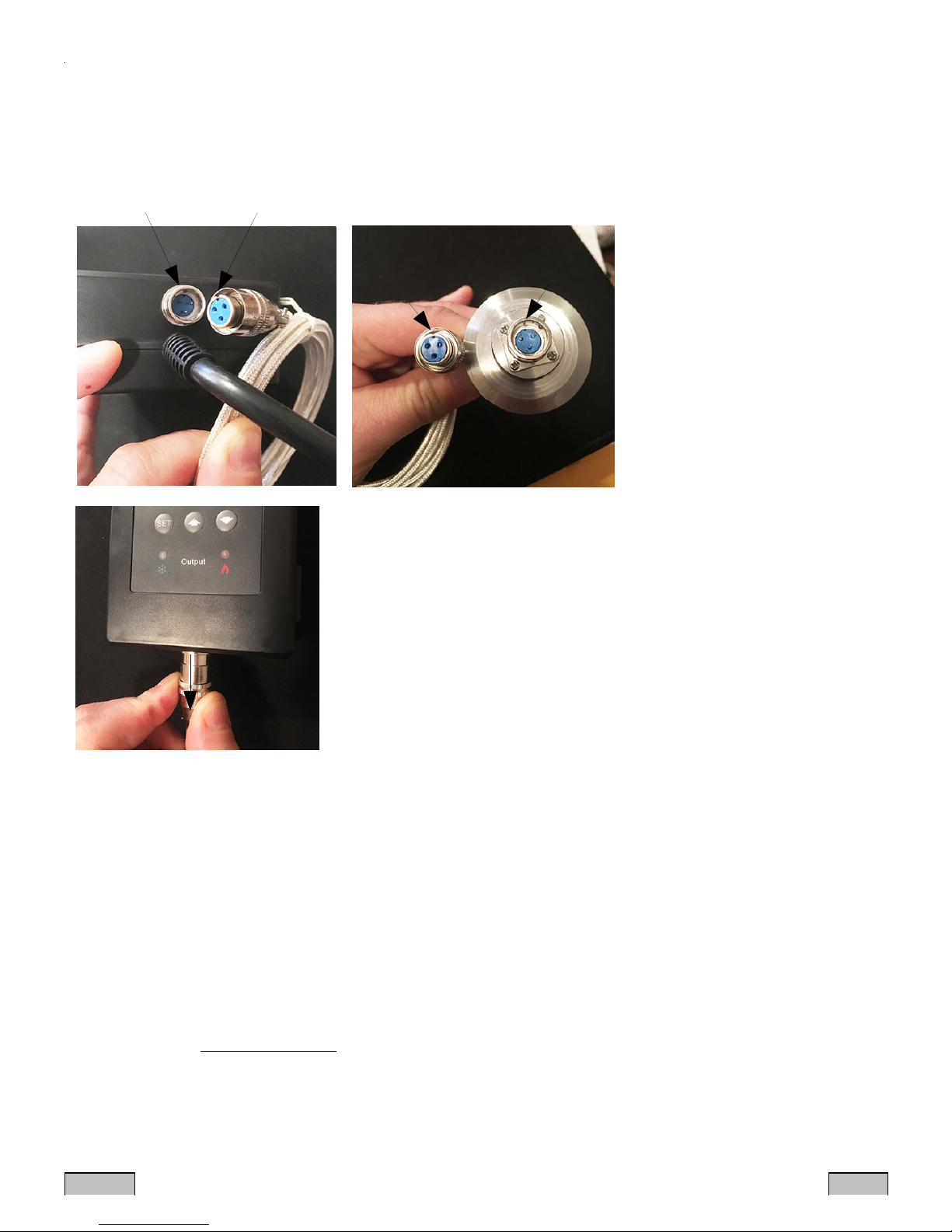
. How to attach the sensor to the unit.
The sensor connector contains a slot for correct pin connection. It
also has a spring lock to prevent disconnections from accidental
pulling on the cable. To attach it to the unit align the slot of the
SFA Controller output when sensor fails
0-0 Cooler and heater off
1-0 Cooler on and heater off
0-1 Cooler off and heater on
BREWHA Equipment Co Ltd. www.brewhaequipment.com
2017.01 P3/3
Questions related to the use of this controller with BREWHA equipment
should be directed to:
BREWHA Eq ipment Co Ltd.
625 Frances Ave
Victoria, BC V8Z1A2
www.brewhaequipment.com
e-mail: [email protected] Tel: 1-844-309-5080
Figure 4. Pull the spring loaded collar to remove the sensor cable.
Figure 3. Ridge on ETC and notch on sensor cable must be aligned when connecting. Same is true for the sensor cable and sensor.
female connector on the temperature probe to the red mark of the
male connector on the ETC unit, then hold the tail and push the
female connector forward. To remove the connector, pull the spring
loaded collar of the female connector back and the female connector
will detach. Please see the Figure 3 and Figure 4 below for details.


