Bticino MH04 Quick start guide

MH04/7G/GB
Temperature control
TECHNICAL GUIDE 04

2MY HOME TEMPERATURE CONTROL

CONTENTS
General features
MY HOME temperature control 4
Zone temperature control 6
The advantages of MY HOME temperature control 10
System examples 12
The solution for all types of system 15
Hydraulic system design 16
Application devices 19
Technical features
Control unit 20
Sensor 22
2-relay actuator 23
4-relay actuator 24
Power supply 25
BUS wire 25
Pull-out terminals 25
Configuration
Device configuration 26
Standard configuration 28
Quick configuration 41
Application examples
4-zone large house with heating using radiators 44
4-zone large house with heating using 2 pumps with solenoid
valves without limit switches, and radiators. 46
6-zone large house with heating using radiant panels 48
8-zone large house with heating using radiators and fan-coil cooling 50
Commercial sector, 12 zones, with fan-coil with two tubes and
three speeds 54
General installation rules
Preparing the building 58
Maximum number of devices 59
Extensive systems 60
Combining with other functions 61
Control unit 62
Sensor 63
Actuators 64
Catalogue 66
3
CONTENTS
CATALOGUE MY HOME TEMPERATURE CONTROL

MY HOME temperature control
The ideal temperature,
when and where you want
MY HOME
WITH ALL THE ADVANTAGES OF A MY HOME SOLUTION
■FITTING IN
■FLEXIBILITY
THE KEY ADVANTAGES OF ZONE TEMPERATURE CONTROL
■COMFORT
A different temperature profile
in every room
■UP TO 30% SAVING
Depending on the type of system
saving on consumption pays for
the system in a few years
■SECURITY
■SIMPLICITY
TEMPERATURE
CONTROL
UNIT
4MY HOME TEMPERATURE CONTROL

The ideal solution for every
application
…and for all types of system
■TERRACED HOUSE
■LARGE HOME
■SMALL COMMERCIAL SECTOR
■OFFICE
GENERAL FEATURES 5
CATALOGUE MY HOME TEMPERATURE CONTROL

Zone temperature control
The guarantee of comfort…
■THE TEMPERATURE PROFILE YOU WANT
•For every room
•For every day of the week
7:00
20:00
From the morning...
... to the evening
06 11824
T3
T2
T1
206 11824
T3
T2
T1
2
06 11824
T3
T2
T1
206 11824
T3
T2
T1
2
22°C in the bathroom19°C in the kitchen
22°C in the bedroom 16°C in the living room
18°C in the bedroom 22°C in the living room
21°C in the kitchen 22°C in the bathroom
06 11824
T3
T2
T1
206 11824
T3
T2
T1
2
06 11824
T3
T2
T1
206 11824
T3
T2
T1
2
6MY HOME TEMPERATURE CONTROL

…and saving
■UP TO 30% SAVING ON CONSUMPTION
•You can turn off the rooms you do not use
•The heat supplied by the sun is not wasted
•The fan-coil speed is adjusted automatically
18°C 24°C
24°C
20°C
… My Home Temperature
control restores the
correct temperature
18°C
20°C
The sun heats some of
the house zones...
BathroomKitchen
Bedroom Living room
Kitchen
Bedroom
21°C
22°C
Bathroom
Living room
GENERAL FEATURES 7
CATALOGUE MY HOME TEMPERATURE CONTROL

Zone temperature control
Traditional solution
■TOO MANY TIMER THERMOSTATS TO PROGRAM
■YOU DO NOT CONTROL THE WHOLE SYSTEM
■CANNOT BE USED IN LARGE SYSTEMS
8MY HOME TEMPERATURE CONTROL

Zone temperature control
MY HOME solution
■JUST ONE CONTROLLER TO PROGRAM
■EFFECTIVE CONTROL OF THE WHOLE SYSTEM
■ALSO SUITABLE FOR LARGE SYSTEMS
GENERAL FEATURES 9
CATALOGUE MY HOME TEMPERATURE CONTROL

The advantages of MY HOME
temperature control
■REMOTE CONTROL VIA THE
MY HOME PORTAL
■SET UP FOR THE REMOTE MANAGEMENT
AND REMOTE ASSISTANCE SERVICE
■SAVING AND COMFORT
•zone temperature control allows different profiles
for each room and for every day of the week.
•depending on the type of system can save up to
30%.
10 MY HOME TEMPERATURE CONTROL

■LOCAL CONTROL
In each room there is a sensor to measure
the temperature which can also control the
system simply:
•± 3°C with respect to the set-point
•switch off the system
• set the antifrost
■
CENTRALISED CONTROL OF THE WHOLE SYSTEM
(UP TO 99 ZONES)
Thanks to the temperature control unit the
whole system can be controlled with a single
command.
It is like having 99 timer thermostats in a single
device.
■JUST ONE CONTROLLER TO PROGRAM
The temperature control unit allows quick
programming thanks to its large display,
navigation of the simplified menu and
keypad like that of a mobile phone.
GENERAL FEATURES 11
CATALOGUE MY HOME TEMPERATURE CONTROL

Heating system
examples
TERRACED HOUSE WITH RADIATOR HEATING
■TRADITIONAL
RADIATOR
bedroom
store-room
living room
kitchen
Kitchen
collector
box
Zone solenoid valves
Store-room Living-room
Bedroom
12 MY HOME TEMPERATURE CONTROL

■RADIANT
PANELS
LARGE HOUSE WITH RADIANT
PANEL HEATING
living room
collector
box
Zone solenoid valves
bedroom kitchen/
store-room
bedroom
store-room
living room
kitchen
GENERAL FEATURES 13
CATALOGUE MY HOME TEMPERATURE CONTROL

Heating and cooling
system examples
■FAN-COIL FOR
HEATING AND
COOLING
OFFICE WITH FAN-COIL HEATING
AND COOLING
office 1
office 2
office 3
office 2
collector
box
Zone solenoid valves
office 3 office 1
14 MY HOME TEMPERATURE CONTROL

My Home temperature control
The solution for all types of system
■HEATING
•radiators
•fan-coil
•radiant panels
TRADITIONAL RADIATORS RADIANT PANELSFAN-COIL
•2 and 4 tubes
•3 speeds
■COOLING
•fan-coil
FAN-COIL
•2 and 4 tubes
•3 speeds
GENERAL FEATURES 15
CATALOGUE MY HOME TEMPERATURE CONTROL

Hydraulic system design
PRIMO PIANO
PIANO TERRA
FIRST FLOOR
GROUND FLOOR
zone solenoid
valves
collector
box
M
TYPE OF SOLENOID VALVE
In a hydraulic system the zones are built up physically
using solenoid valves. Each zone can thus be
managed independently by controlling the individual
solenoid valves.
2 types of solenoid valves are used in the systems:
•ON/OFF, which requires an ON/OFF contact
•Open/Close, which requires an Open/Close contact
ON/OFF solenoid valve Open/Close solenoid valve
Installing the solenoid valves in the collector box
PLACING THE SOLENOID VALVES
In heating systems the typical installations has all the
solenoid valves positioned on the collector, grouped
in a box in the boiler room. In dwellings on several
floors this solution can be replicated for each floor.
In fan-coil systems the solenoid valve can be installed
inside the fan-coil itself.
In 2-tube systems there is just one solenoid valve
for both the heating and cooling functions. In 4-tube
systems there are 2 solenoid valves, one each for the
heating and cooling functions.
Installing a collector box for each floor
16 MY HOME TEMPERATURE CONTROL

M
M
Installing the solenoid valve in a 2-tube fan-coil
Installing the solenoid valve in a 4-tube fan-coil
GENERAL FEATURES 17
CATALOGUE MY HOME TEMPERATURE CONTROL

Designing a hydraulic
system
Fan-coil ChillerRadiant panels
Electric radiator Boiler
ON/OFF solenoid valve Radiator
PLACING THE SOLENOID VALVES IN RADIANT
PANEL SYSTEMS
Radiant panel systems are always managed in zones
and their solution is very similar to that of radiator
systems.
The zones are built up by means of solenoid valves
grouped on the collector, but there is also a water
mixture valve.
This valve is proportional and cannot be controlled by
the My Home temperature control.
This valve mixes the water so that a set water
temperature limit and thus floor temperature limit
is not exceeded, which could be annoying and
dangerous.
Open/Close solenoid valve
M
Pump
SYMBOL LEGEND
Radiant panels Three-way mixing valve
M
For this reason this valve must be controlled by a unit
supplied by the panel system manufacturer, or it is
simply a thermostatic valve on which a fixed water
temperature limit is set.
Valve general symbol
18 MY HOME TEMPERATURE CONTROL

MY HOME
temperature control
APPLICATION DEVICES
A My Home temperature control system can manage
up to 99 zones. The system is on a 2-wire bus and
made up of the following devices:
Temperature control unit:
this configures the system, customises the programs
and displays information.
Sensors:
at least one sensor must be installed in every zone.
They measure the room temperature and can locally
vary the temperature set on the control unit.
Actuators:
operate the solenoid valves and the circulation
pumps. The number and type of actuators are chosen
depending on the type of solenoid valves installed and
their location in the system.
Just one contact is used to control the ON/OFF solenoid
valves, while the two-relay interlock is used for the
open/close solenoid valves. The four-relay actuator
controls the fan-coils and also automatically controls
the 3 speeds.
The ideal system solution is to have the solenoid
valves grouped on the collector, so that a board
can be made containing the actuators near the
box.
This makes wiring simpler with a small number of
actuators.
ART.F430/2
1234
C1 C2
1234
ART.F430/2
1234
C1 C2
1234
ART.F430/2
1234
C1 C2
1234
ART.F430/2
1234
C1 C2
1234
solenoid valve
actuators unit
zone solenoid
valves
collector
box
Control unit
Sensor
Zone 1
Sensor
Zone 2
Sensor
Zone 99
BUS
2-relay
actuator
4-relay
actuator
Power supply
GENERAL FEATURES 19
CATALOGUE MY HOME TEMPERATURE CONTROL

LEGEND
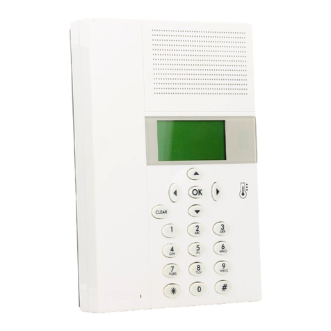
1) Graphic display: shows the messages which guide the programming
operations and the system state.
2) Navigation keypad: allows navigation within the menus and confirms or
deletes programming operations.
3) Alphanumeric keypad: allows manual entry of all those programming
operations which require the use of numbers and/or symbols.
4) Battery compartment: housing for battery item 3507/6.
The Control unit, which can only be used for the BTicino temperature
control function, can set the system and modify the system mode of
operation. Equipped with management software with guided menus shown
on the display, it allows the user to chose the mode of operation, display
the temperatures of the various zones and display and modify the daily
temperature profiles and the weekly programs, while the maintenance
menu, reserved for the installer (password protected), allows access to the
system settings (zone configuration, system test, total reset, etc.).
TEMPERATURE CONTROL UNIT ITEM 3550
1
2
3
DATA
Power supply: from 18V to 28V BUS
Maximum absorption: 75 mA
Size: L = 140 H = 210 D = 35
Degree of protection: IP30
Operating temperature: from 5°C to 40°C
Temperature setting: from 5°C to 40°C ± 0.5°C
Technical
features
The Control unit can provide both heating and cooling and can manage up to
99 different zones (with a Master sensor and/or detector for each zone plus
any Slave detectors).
A contact can be connected in input for remote control (switching from
the antifrost mode to automatic and vice versa) by means of a telephone
actuator.
4
5
6
7
8
5) Reset pushbutton: pushbutton to reset the hardware.
6) Serial connector: connects to a PC via cable item 335919
7) Remote control: connection terminal.
8) BUS: BUS connection terminal.
20 MY HOME TEMPERATURE CONTROL
This manual suits for next models
5
Table of contents
Other Bticino Temperature Controllers manuals