Brickcom OB-200Np-S Datasheet

Easy Installation Guide
Megapixel Network Camera
OB-200Np-S

Preface
Safety Instruction
Do not expose the camera in the environment not defined in the Guide.
Do not focus the camera lens on strong light such as the sun or incandescent lamp. The strong light can
cause overexposure or light leak (not camera malfunction), which may shorten camera lifetime.
When cleaning the lens, please use a rubber dust blower or lens cleaning cloth to remove the dirt. When
cleaning transparent housing, please use soft and dry cleaning cloth to wipe it gently. Never apply any
cleanser with ethanol or benzene in it
Do not drop the camera or subject it to physical shock.
If the product does not work properly, please contact your dealer or the nearest service center. Never
attempt to disassemble or repair the product yourself in any way.
Please adopt power supply in the safety voltage range.
Humidity 10%~95% (non-condensing)
Altitude
Atmospheric Pressure
-60m~3000m
86kPa~106kPa
Working Voltage
DC12V/AC24V
Temperature
-40℃~70℃
Operating Environment
1
Thank you for purchasing our product. If there are any questions, or requests, please do not hesitate to contact
us.
Every effort has been made to ensure the accuracy and validity of this Guide. Any update of this Guide is
subject to change without notice. For the latest document, please contact the dealer.
These instructions are intended to ensure that the user can use the product correctly to avoid danger or
property loss. Please read this Guide carefully before using the product, and keep it properly for future
reference. If the product cannot work normally or is damaged because the user does not follow the safety
instructions, we shall not assume any responsibility.
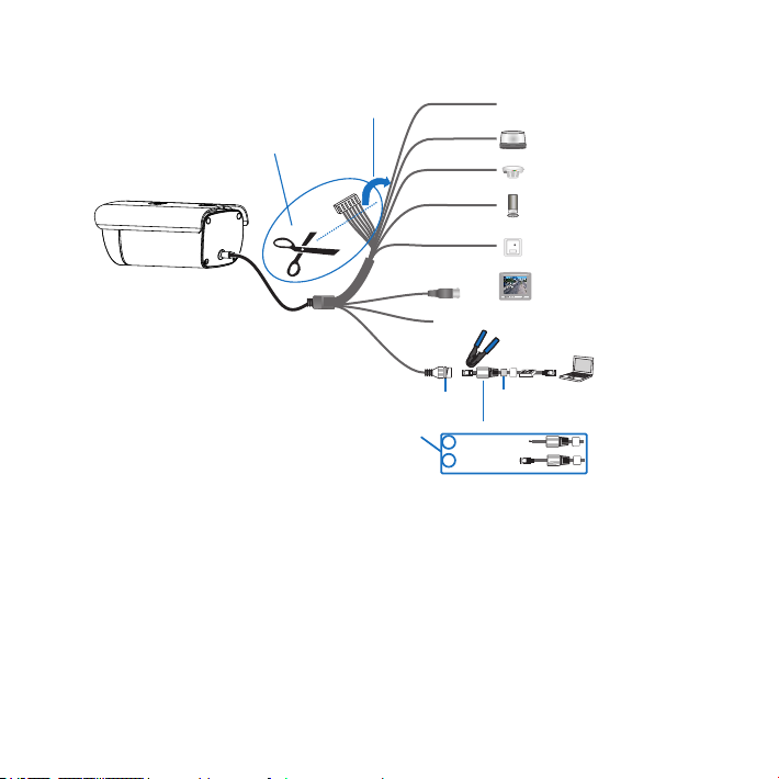
The camera is IP67-rated. When expose it outdoor, remember to handle with the back cable of the camera
and make it water-proof.
When it is necessary to replace a part, please contact your dealer in advance and replace the part with
specified model or part of the same features. We shall not assume any responsibility for problems caused by
unauthorized replacement.
While shipping the camera, pack it in the factory packing or use materials with equivalent quality.
Keep the camera away from water or any liquid.
[Note]: Different models support different working voltages. Please provide power according to the tags at
the power connector of specific product.

Installation Steps
2
Models with brackets support ceiling mount and wall mount. Please get the accessories ready before
installation.
1. TF card installation.
[Note]: The installation surface must be thick enough and can bear weight at least 8 times of the camera and
the bracket.
Models without brackets support ceiling bracket mount, wall bracket mount, beam bracket mount or pole
bracket mount. Please get the accessories ready before installation..
[Note]: Max memory of TF card can be 128G.
Wall Mount Ceiling Mount
Camera Weight: 2.5kg
Base Size
55.6
4-¢5.0
66.9
Camera Weight (excluding bracket and accessories): 2kg
Wall Bracket Mount Ceiling Bracket Mount Beam Bracket Mount Pole Bracket Mount Bottom Size
2-1/4-20, depth 8
50
Take down the sealing gland, insert TF card in the slot
and screw up the sealing gland.

3
the most connectors as example, and the tag meanings are explained in the picture:
2. Connect cables and power on. Different sub models have different connector interface. Take the model with
RS-485 Port
CVBS Output
ALARM IN
AUDIO IN
AUDIO OUT
Connect to surveillance keyboard or alarm expander
ALARM OUT
PICKUP
Connect cables as indicated
Cut off terminal and connect
10/100M
Adaptive
Client
Rubber Cushion Rubber Ring
Water-proof part of the cable, must be installed and tightened.
Steps:
2
1Route the cable
Make a RJ-45
connector
[Note]: Some models support PoE. Only have to connect to PoE switch for power supply. For wiring, please
refer to the Appendix.
Power connector
(connect subject to the parameters on power supply tag)
Login to Client
1. Minimum configurations and system requirements:
ŸDirectX:9.0c
ŸBrowser: IE7.0 and newer version, Firefox, Google Chrome (41 and lower)
ŸOperating System: Windows XP or newer version
ŸRAM Memory: 4GB or above
ŸProcessor: 3.3 GHz CORE®i3 series or other equivalent processors

4
2. Device Activation
When using the device for the first time, run IPCSearch: it will search devices in LAN automatically and
display the list of device IP address, gateway and etc. If the network provides DHCP service, DHCP server
will assign IP for the camera automatically.
·Web client: the device can also be activated through the web client. Set PC and the device in the same
network segment and login to the web. User can set admin password and password reset email on the
interface and click "Activate".
·Individual: Select the device from IPCSearch and right click to select “Activate”. Fill admin user name and
password and the e-mail address to find back the password. Click “Activate” and the camera will reboot.
·Batch: Select the device and click “Batch processing”. In the popup interface, set admin user's password
and the email address to find back the password. Click “Activate” and the camera will reboot.

5
3. Modify device IP address
4. Login to the device
1) Double click the device in IPCSearch or click “Login”. Enter user name and password to login the web client.
will reboot automatically.
user name (admin) and the password set before activation should be entered. After configuration, the camera
check “Custom device address (Close DHCP)” and fill the Ethernet parameter. During the modification, the
Click “Modify Params” and set the network parameters. When configuring a static IP for the camera, please

3) Re-login to the web client and view live video directly.
2) After login, download and install the plug-in. Close browser during installation.
[Note]: Interface of different models may differ. Please subject it to the actual product. Please refer to the Help
file for detailed explanation.
Adjust camera direction, configure camera parameters in web client until the live view meets requirement.
6

NO.
1RS485_A
Tag
Color
Group
Remarks
One
Group
One
Group
One
Group
Appendix Cable Identification
Alarm Output 1, regardless
of positive and negative
RS-485 Serial Port A
RS-485 Serial Port B
Audio Output
Audio Grounding
Alarm Input 1
Alarm Input Grounding
White/Red
Green
Brown
Pink
White
Light Green
White/Orange
Yellow
White/Black
White/Green
2
3
4
5
6
7
8
9
10
ALARM_OUT 1B
ALARM_OUT 1A
ALARM_IN_GND
ALARM_IN 1
AUDIO_GND
AUDIO_OUT
AUDIO_IN 2
AUDIO_IN 1
RS485_B
11
12
13
14
White/Yellow
Video Grounding
Video Output
Audio Grounding
AUDIO_GND
AUDIO_GND
White/Brown
Black
White
BNC1_GND
BNC1
One
Group
Audio Grounding
Audio Input 1
Audio Input 2
7

V5 20 190716
Table of contents
Other Brickcom Digital Camera manuals