Brickcom VD-200Np-S Datasheet

Easy Installation Guide
Megapixel Network Camera
VD-200Np-S
1
During installing and using the device, please follow local electrical safety regulations strictly.
Please use power supply in the safe voltage range of our product. Make sure if the power supply is correct
before running the device.
Please install an easy-to-use breaker during installation and wiring in case it is necessary to make an
emergency break.
Please prevent the power cord from being trampled or pressed especially the plug, socket and the connecting
part led out from the device.
Please connect cables of power, alarm, audio and RS-485 with the power off. Hot-line wiring is not allowed.
Do not focus the camera lens on strong light such as the sun or incandescent lamp; otherwise the strong light
will cause overexposure or light leak (not camera malfunction), which may shorten camera lifetime.
Please transport, use and store the device within defined humidity and temperature ranges.
Keep the camera away from water or any liquid to avoid damage to internal components.
Do not expose it in damp, dusty, extremely hot or cold places or places with intense electromagnetic radiation
or with unstable lighting.
While shipping the camera, pack it in the factory packing or use materials with equivalent quality.
To avoid heat accumulation, please do not block the ventilation around the device.
When shipping, storing and installing the device, try to prevent it from damages caused by pressure, violent
vibration and soaking.
This product is not water-proof and cannot be used outdoor alone.
1. Power Supply
2.Working Environment
I. Preface
II. Safety Instruction
These instructions are intended to ensure that the user can use the product correctly to avoid danger or
property loss. Please read this Guide carefully before using the product, and keep it properly for future
reference. If the product cannot work normally or is damaged because the user does not follow the safety
instructions, we shall not assume any responsibility. Thanks for your cooperation.
Thank you for purchasing our product. If there is any question, please do not hesitate to contact us.
Working Environment
DC12V±10%/POE, Power: 10W max
-40℃~70℃
10%~95% (non-condensing)
86kPa~106kPa
-60m~3000m
Voltage
Temp.
Humidity
Altitude
Pressure

2
3. Daily Maintenance
4. Special Statement
Do not touch the heat component of the device directly to avoid empyrosis.
When the lens is contaminated by dust or grease, use cotton cloth or lens clean cloth to wipe it off. When it is
hard to clean, dip some lens cleanser and wipe gently and rotate outward from the middle until it is clean.
Never apply any organic solvent with ethanol or benzene to clean the lens and housing.
Do not disassemble or repair the device in any way by yourself. We shall not assume any responsibility for
problems caused by unauthorized repair or maintenance.
If the product does not work properly, please contact your dealer or the nearest service center.
The product appearance is subject to the actual device and picture in this Guide is for reference only..
Every effort has been made to ensure the accuracy and validity of this Guide. Any update of this Guide caused
by version upgrade is subject to change without notice.
This Guide is made for multiple models but it will not illustrate one by one. Please refer to it according to the
actual products you are using.
This device can be used after being activated through IPCSearch with a valid email address for claiming the
password.
To ensure the safety of device on internet, it is strongly recommended that you set a strong password which is
composed of at least 2 kinds of the following, digits, case-sensitive letters or specific symbols, and whose
length ranges from 8 to 16 bits. Please modify the password periodically and once every 3 months is
recommended. If the device is used in highly risky environment, suggest modifying the password monthly or
weekly. Please keep your user name and password safe.
Accessing this device to the internet is at user's own risk, including but not limited to the possible network
attack, hacker attack, virus infection and etc. This company will not assume any responsibility for problems of
product abnormality and information disclosure caused thereof. We shall provide technical support relating to
the products in time.

3
III. Appearance and Interface
1
Components:
Dimensions:
5
2
4
3
122
84.77
53.76
96.13
∅111
3-∅5
120°
120°
Unit: mm
No. Part Name
1 Sem i-dome
2 Movement module
3 Lens -adjus ting screw
4 Bas e
5 Side wiring hole

4
Buttcock line:
1
2
3
4
Interface
Cable
Group
Table 1 Wiring Interface
Table 2 Cable Group Interface
1 Yellow
2 Green
3Pink
4White
5B / W
6 Light
Green
7Gray
8Red
9Blue
10 Purple
RS-485-A
RS-485-B
RS-485 serial port, to control external devices
such as third-party device
Audio input port, for inputting audio signal or
intercommunication
Audio output port, for outputting audio signal
Audio grounding
Alarm input port, for inputting alarm signal
Alarm input grounding
Alarm output port, for outputting alarm signal
AUDIO IN-1
AUDIO IN-2
AUDIO OUT
AUDIO GND
ALARM IN GND
ALARM OUT-1-A
ALARM OUT-1-B
ALARM IN
No.Color Name Function
Interface
1
2
3
4
User cable group Including alarm in / out, audio in / out, RS-485 serial port and etc.
Local video output composite video signal, BNC port
Connect to power supply of DC12V
Connect to network access devices like a switch
Video output
Power supply
Network
Interface Name Function

5
IV. DC12V Wire Diameter VS. Transmission Distance
The recommended max transmission distance when the wire diameter is certain and the DC12V voltage loss
rate is less than 10% (For DC12V powered devices, the maximum allowed voltage loss rate is 10%. All the
wires in the following table are cooper wires, whose electrical resistivity is ρ = 0.0175Ω*mm2/m)
Diameter
(mm)
0.8(20AWG)
1.0(18AWG )
1.25(16AWG)
2.0(12AWG )
5
38(125)
61(199)
96(315)
244(801)
10
19(63)
30(99)
48(157)
122(400)
15
13(42)
20(66)
32(105)
81(267)
20
10(31)
15(50)
24(79)
61(200)
25
8(25)
12(40)
19(63)
49(160)
30
6(21)
10(33)
16(52)
41(133)
35
5(18)
9(28)
14(45)
35(114)
40
5(16)
8(25)
12(39)
31(100)
45
4(14)
7(22)
11(35)
27(89)
50
4(13)
6(20)
10(31)
24(80)
55
3(11)
6(18)
9(29)
22(73)
60
3(10)
5(17)
8(26)
20(67)
65
Note 1
5(15)
7(24)
19(62)
70
Note 1
4(14)
7(22)
17(57)
75
Note 1
4(13)
6(21)
16(53)
80
Note 1
4(12)
6(20)
15(50)
85
Note 1
4(12)
6(19)
14(47)
90
Note 1
3(11)
5(17)
14(44)
95
Note 1
3(10)
5(17)
13(42)
100
Note 1
3(10)
5(16)
12(40)
Distance
(m)
Power (W)
[Note]: 1. When the transmission power is over 60W, you must use wires with diameter of 1.0 (18AWG) or
above;
2. The requirements of diameter apply to single, solid and round cooper wire. The AWG value of multi-
stranded wires is dependent on the total CSA (Cross Sectional Area) of all wires.

V. Installation
6
Ceiling Mount:
The installation steps of ceiling mount and wall mount are the same. This part will take ceiling mount as an
example to introduce the installation steps. During the installation, please keep the transparent dome clean
both inside and outside.
You can perform ceiling or wall mount when the wall or ceiling are thick and solid enough for fixing self-tapping
screws and meanwhile strong enough for bearing the device.
Pendent mount Wall bracket mount
Ceiling mount Wall mount
Camera weight: 0.6kg (net)
When installing the device outdoor, a waterproof joint box is necessary to get good waterproofness. As the
waterproof joint box is optional, please contact your supplier or customer service personnel to purchase.
The waterproof joint box and its installation sketch are shown below. Please refer to the Quick Start Guide of
the waterproof joint box for detailed installation.
The camera supports ceiling mount, wall mount, pendent mount and wall bracket mount. As pendent mount and
wall bracket mount need brackets but the device itself does not contain brackets, please contact your supplier
or customer service personnel to purchase.
7
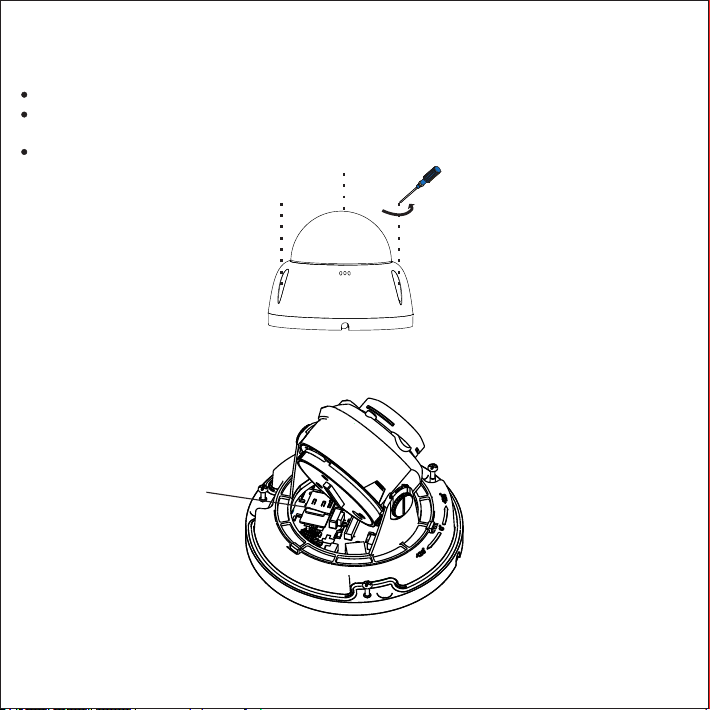
2. Install TF card (optional). Insert a TF card into the slot as shown in the following picture. The max supported
memory of TF card is 128G. After insertion, hot-swapping the TF card is not recommended.
Insert TF card
3. Paste the installation sticker. Pick out the installation sticker from the attachment and stick it to the ceiling or
wall according to the surveillance area. Size of the sticker is shown in the following picture.
1. Take down the dome housing. Use a screw driver to screw off the 3 cross recessed pan tamper screws and
take down the dome housing.
Note:
Do not put the transparent dome housing on the ground when taking it down to avoid scratching.
Prevent scratching the internal of the dome housing with the screw driver during operation; otherwise the
image quality will be affected.
Do not peel off the protective film inside and outside the dome housing until finishing installation.
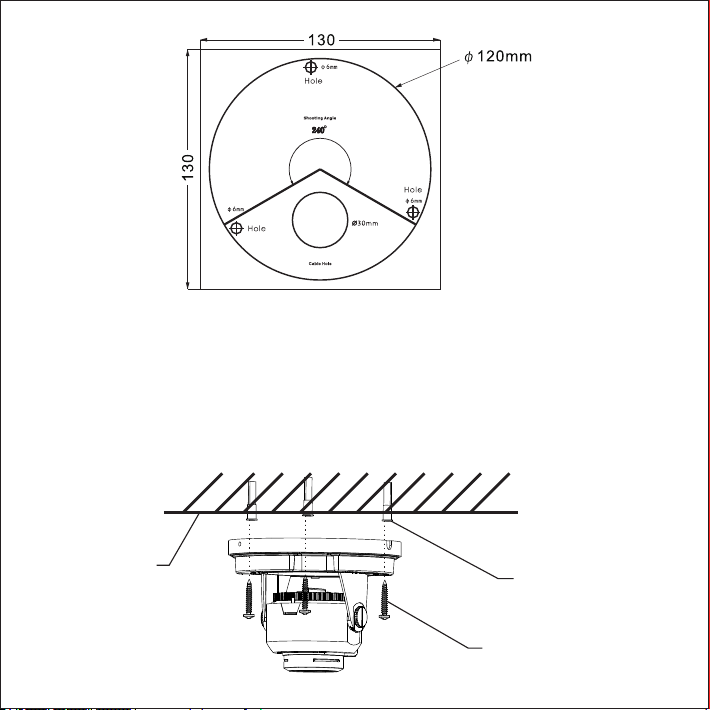
4. Drill holes. Drill 3 basic holes with plastic expansion screw bolts at the 3 "cross" hole marks on the sticker and
insert the 3 expansion screw bolts thoroughly into the holes.
5. Fix the device base onto the wall. Adjust the base of the device, route the cables through the cable hole, align
the 3 screw holes on the device base to the 3 plastic expansion screw bolts on the mounting surface, tighten
the 3 tapping screws into the expansion screw bolts and fix the dome camera onto the surface.
[Note] If routing the cables from the top of the mounting surface, a cable outlet hole is also needed at the part
of "Cable Hole" on the sticker. If routing the cables from the profile side of the device, lead the cables out
through the U-shaped groove at the side of the dome base.
Expansion screw bolts
Install screws
Ceiling or wall
8

9
7. Install dome housing. Pick up the dome housing, peel off the protective film inside the transparent dome,
align the screw holes on the dome housing to that on the base and cover the housing. Tighten the 3 cross
recessed pan tamper screws with a screw driver and fix the dome housing onto the base. Finally, peel off the
protective film outside the transparent dome housing.
8. Connect cables and power on the device.
Pan rotation ±120°
120°
120°
Tilt rotation 25°-90°
6. Adjust lens surveillance direction. Loosen the lens angle-adjusting screw, rotate the dome manually and the
lens will rotate in pan and tilt directions. Rotate the rotating part at the back of the lens. When the lens rotates
till ±90°, set the mode as corridor mode while 0° as common mode. It's inadvisable to rotate too hard during
adjustment to avoid damage to the parts. After finishing adjustment, tighten the lens angle-adjusting screw.
65°
Rotating
part
Lens angle-
adjusting screw

Pendent Mount:
Though the pendent bracket is different with the wall bracket, their installation method is quite similar. Now
take the pendent bracket as an example to illustrate the installation steps, which is also a reference for wall
bracket mount.
When choosing pendent or wall bracket mount, please make sure that the mounting wall or ceiling is thick and
solid enough for fixing tapping screws and meanwhile strong enough for bearing the total weight of the device
and the bracket.
Size of the wall bracket is shown below:
86.3
86.9
8
114
175
∅122
250
M4
Hole-tight
screws
∅40
∅92
10
1. Drill holes. Determine the hole positions on the wall according to the holes on the base of the bracket drill ,
holes on the wall and insert expansion screw bolts .
If routing the cables from the top of the mounting surface, a cable outlet hole is also needed on the wall. If
routing the cables from the profile side of the device, lead the cables out through the U-shaped groove at the
base of the bracket.
Weight: 0.6KG
Weight: 0.55KG
Unit: mm
120
120
11
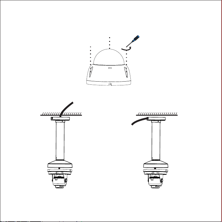
2. Take down the dome housing. Use a screw driver to screw off the 3 cross recessed pan tamper screws and
take down the dome housing.
Do not put the transparent dome housing on the ground when taking it down to avoid scratching.
4. Align the 3 screw holes on the device base to the 3 screw holes on the bracket, tighten the 3 screws and fix the
dome camera onto the bracket.
3. Route cables. If routing the cables from the top, lead the cables through the mounting surface. If routing the
cables from the profile side of the device, lead the cables out through the U-shaped groove at the base of the
bracket.
Top wiring Side wiring
[Note] The outer diameter of the drill should match with that of the expansion screw bolt and the hole
deepness match the screw bolt length.

12
5. Fix bracket. Align the 4 screw holes on the bracket base to the 4 expansion screw bolts on the mounting
surface, tighten the 4 tapping screws into the expansion screw bolts and fix the pendent bracket onto the
mounting surface.
6. Refer to Step 6 -7 of Ceiling Mount for lens direction adjustment and dome housing installation.
7. Connect cables and power on the device.
VI. Login to Client
13
1. Minimum configurations and system requirements:
2. Device Activation
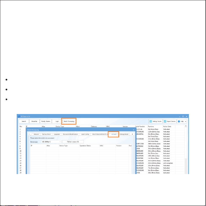
When using the device for the first time, run IPCSearch: it will search devices in LAN automatically and display
the list of device IP address, gateway and etc. If the network provides DHCP service, DHCP server will assign
IP for the camera automatically.
Batch: Select the device and click “Batch processing”. In the popup interface, set admin user's password and
the email address to find back the password. Click “Activate” and the camera will reboot.
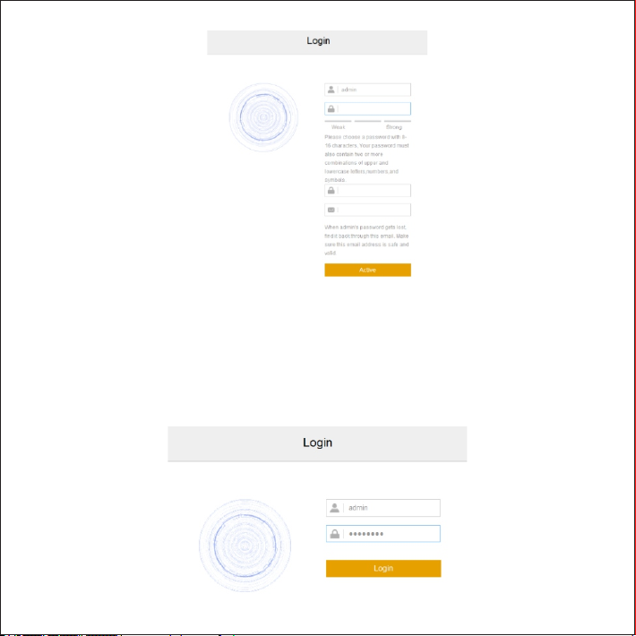
Individual: Select the device from IPCSearch and right click to select “Active”. Fill admin user name and
password and the e-mail address to find back the password. Click “Activate” and the camera will reboot.
Web client: the device can also be activated through the web client. Set PC and the device in the same network
segment and login to the web. User can set admin password and password reset email on the interface and
click "Activate".
ŸProcessor: 3.3 GHz CORE®i3 series or other equivalent processors
ŸRAM Memory: 4GB or above
ŸOperating System: Windows XP or newer version
ŸBrowser: IE7.0 and newer version, Firefox, Google Chrome (41 and lower)
ŸDirectX:9.0c
14
3. Modify device IP address
4. Login to the device
1) Double click the device in IPCSearch or click “Login”. Enter user name and password to login the web client.
Click “Modify Params” and set the network parameters. When configuring a static IP for the camera, please
check “Custom device address (Close DHCP)” and fill the Ethernet parameter. During the modification, the
user name (admin) and the password set before activation should be entered. After configuration, the camera
will reboot automatically.

15
2) After login, download and install the plug-in. Close browser during installation.
3) Re-login to the web client and view live video directly.
[Note]: Interface of different models may differ. Please subject it to the actual product. Please refer to the Help
file for detailed explanation.
Adjust camera direction, configure camera parameters in web client until the live view meets requirement.

V1 20 190716
Table of contents
Other Brickcom Digital Camera manuals


