Brickcom OSD-200Np-S 30X Datasheet

Easy Installation Guide
Megapixel Network Camera
OSD-200Np-S 30X

1
During installing and using the device, please follow local electrical safety regulations strictly.
Please use power supply in the safe voltage range of our product. Make sure if the power supply is correct
before running the device.
Please install an easy-to-use breaker during installation and wiring in case it is necessary to make an
emergency break.
Please prevent the power cord from being trampled or pressed especially the plug, socket and the
connecting part led out from the device.
Please connect cables of power, alarm, audio and RS-485 with the power off. Hot-line wiring is not allowed.
Please use the attached power adaptor. Using unqualified power adaptor may cause damage to the device.
Do not focus the camera lens on strong light such as the sun or incandescent lamp; otherwise the strong light
will cause overexposure or light leak (not camera malfunction), which may shorten camera lifetime.
For device with laser, when it is working, never look into the laser window directly in short distance. Neither
look at the laser directly nor look at the reflection of it.
Please transport, use and store the device within defined humidity and temperature ranges.
Do not expose it in damp, dusty, extremely hot or cold places or places with intense electromagnetic radiation
or with unstable lighting.
Keep the camera away from water or any liquid to avoid damage to internal components.
Usually this device is installed outdoor, so please make special treatment such as water proofing, damp
proofing and dust proofing to the connection part of it, especially that the screw at the connection part must
be tightened to ensure general leakproofness. To avoid lightning stroke, please install an arrester.
To avoid heat accumulation, please do not block the ventilation around the device.
While shipping the camera, pack it in the factory packing or use materials with equivalent quality.
When shipping, storing and installing the device, try to prevent it from damages caused by pressure, violent
vibration and soaking.
During transportation, conduct special protection over the front side of the camera to avoid friction, scratch
or contamination to it. To keep the front side clean, do not peel off the protective film on the front side until
finishing installation.
Power Supply
Working Environment
I. Preface
II. Safety Instruction
These instructions are intended to ensure that the user can use the product correctly to avoid danger or
property loss. Please read this Guide carefully before using the product, and keep it properly for future
reference. If the product cannot work normally or is damaged because the user does not follow the safety
instructions, we shall not assume any responsibility. Thanks for your cooperation.
2
Daily Maintenance
Special Statement
Working Environment
AC24V±10% / Hi-PoE
-40℃~70℃
10%~95% (Relative, non-condensing)
Waterproof, lightning protection, anti-interference
Voltage
Temp.
Humidity
Condition
Altitude
Pressure 86kPa ~ 106kPa
-60m ~ 3000m
Do not touch the heat component of the device directly to avoid empyrosis.
When the lens is contaminated by dust or grease, use cotton cloth or lens clean cloth to wipe it off. When it is
hard to clean, dip some lens cleanser and wipe gently and rotate outward from the middle until it is clean.
Never apply any organic solvent with ethanol or benzene to clean the lens and housing.
Do not disassemble or repair the device in any way by yourself. We shall not assume any responsibility for
problems caused by unauthorized repair or maintenance.
When it is necessary to replace a part, please contact your dealer in advance and replace the part with
specific model or part of the same features. We shall not assume any responsibility for problems caused by
unauthorized replacement.
If the product does not work properly, please contact your dealer or the nearest service center.
The product appearance is subject to the actual device and picture in this Guide is for reference only.
Every effort has been made to ensure the accuracy and validity of this Guide. Any update of this Guide
caused by version upgrade is subject to change without notice.
This Guide is made for multiple models but it will not illustrate one by one. Please refer to it according to the
actual products you are using.
This device can be used after being activated through IPCSearch. During activation please fill a valid email
address for finding back the password.
To ensure the safety of device on internet, it is strongly recommended that you set a strong password which
is composed of at least 2 kinds of the following, digits, case-sensitive letters or specific symbols, and whose
length ranges from 8 to 16 bits. Please modify the password periodically and once every 3 months is
recommended. If the device is used in highly risky environment, suggest modifying the password monthly or
weekly. Please keep your user name and password safe.
Accessing this device to the internet is at user's own risk, including but not limited to the possible network
attack, hacker attack, virus infection and etc. This company will not assume any responsibility for problems
of product abnormality and information disclosure caused thereof. We shall provide technical support
relating to the products in time.
3
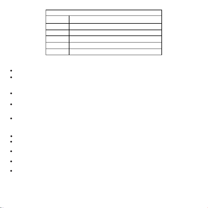
III. Dimensions and Wire Interfaces
Dimensions
For outdoor installation, suggest using the wall bracket whose arm has a certain upward angle.
If user uses self-selected bracket, suggest applying those waterproof brackets with internal screw thread
connector. If user selects brackets with external screw thread, make sure of the waterproofness of the
connecting part between the bracket and the dome camera.
The screw thread connector needs to be bound with thread seal tape to ensure the sealing tightness of
screw thread. When mount, align with the screw thread to avoid obvious deviation or slipping.
Waterproofing
Unit: mm
193.1
39
339.5
222.7
S 173.3
156
Connector
G 1½
36
40
13
12 3-M6
29
3.4
41 C1
18
12.9
28
6.2
50
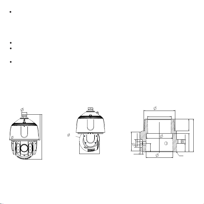
Components
4
No.
Component
No.
Component
No.
Component
1
Tail Wire
5
Lens Film
9
Safety Hook
2
Adaptor
6
Dome Housing
10
Hanger
3
Straight Side of D
7
IR Light
11
Buckled Lid
4
Lens
8
IR Light Film
1
Rubber ring
Client
Switch
AC IN 100~240V 50/60Hz
PoE/D ATA DATA/IN
PSE
2
Wire Interface
[Note]: Power supply of the camera is either PoE or AC24V.
10
9
5
1
2
7
4
3
11
86
3
4
5
6

5
Interface
No.
Color
Port Name
Function
Cable
Group
1
Green
ALARM OUT B
Alarm output port, for outputting alarm signal
Can be connected to: alarm light
2
Purple
ALARM OUT A
3
Orange
ALARM IN-2
Alarm input port, for inputting alarm signal
Can be connected to: smoke detector, voice-operated switch
4
Blue
ALRAM IN -1
5
Yellow
ALARM GND
Alarm grounding
6
Brown
AUDIO OUT
Audio output port, for outputting audio signal
Can be connected to: loudspeaker box
7
Red
AUDIO IN
Audio input, inputting audio signal or intercommunication
Can be connected to: sound pick-up
8
Black
AUDIO GND
Audio grounding
Table 2 Cable Group Interface
[Note]:
1) ALARM OUT A and ALARM OUT B are regardless of positive and negative polarities and they form a group of
alarm output.
2) ALARM IN-1 and ALARM IN-2 share ALARM GND wire.
3) AUDIO IN and AUDIO OUT share AUDIO GND wire.
No.
Port Name
Function
1
Network port
Connect to PoE/DATA port of PSE box
3
Power supply (AC24V1, red)
Connect to power supply of AC 24V, regardless of positive and negative
4
Power supply (PGND, yellow/green)
Grounding wire, connect it to reliable grounding point
5
Power supply (AC24V2, black)
Connect to power supply of AC 24V, regardless of positive and negative
6
User cable group
Including alarm in / out and audio in / out
Table 1 Wiring Interface
2ACDC Power_PSE PoE/DATA port to camera, DATA/IN to switch, AC/IN port to power

0.8000
1.000
1.250
2.000
10
283 (86)
451 (137)
716 (218)
1811 (551)
20
141 (42)
225 (68)
358 (109)
905 (275)
30
94 (28)
150 (45)
238 (72)
603 (183)
40
70 (21)
112 (34)
179 (54)
452 (137)
50
56 (17)
90 (27)
143 (43)
362 (110)
60
47 (14)
75 (22)
119 (36)
301 (91)
70
40 (12)
64 (19)
102 (31)
258 (78)
80
35 (10)
56 (17)
89 (27)
226 (68)
90
31 (9)
50 (15)
79 (24)
201 (61)
100
28 (8)
45 (13)
71 (21)
181 (55)
110
25 (7)
41 (12)
65 (19)
164 (49)
120
23 (7)
37 (11)
59 (17)
150 (45)
130
21 (6)
34 (10)
55 (16)
139 (42)
140
20 (6)
32 (9)
51 (15)
129 (39)
150
18 (5)
30 (9)
47 (14)
120 (36)
160
17 (5)
28 (8)
44 (13)
113 (34)
170
16 (4)
26 (7)
42 (12)
106 (32)
180
15 (4)
25 (7)
39 (11)
100 (30)
190
14 (4)
23 (7)
37 (11)
95 (28)
200
14 (4)
22 (6)
35 (10)
90 (27)
Distance
(feet (m))
D
(mm)
Power (VA)
6
IV. AC 24V ire Diameter VS. Transmission DistanceW
The recommended max transmission distance when the wire diameter is certain and the AC 24V voltage loss
rate is less than 10% (For devices powered by alternative current, the max allowed voltage loss rate is 10%.
For example, the rated power of a device is 100VA and it is installed 28 inch (8m) away from the transformer,
the required minimum wire diameter is 0.8000mm.)

V. Safety Examination
The tail wire should be treated waterproof and well protected without being exposed outside. The whole part in
which the tail wire is in should be made waterproof generally and avoid soaking it in water. When installing the
dome camera, make sure the connecting part between the dome camera and the bracket is treated sealed and
waterproof.
Before starting installing dome camera, please take off the air column bag and peel off the tape fixing the
dome and wear the gloves.
Please reserve enough mounting space before installation.
The wall or ceiling can bear the weight as heavy as 8 times of the total weight of the dome camera and the
accessories such as the bracket (net weight of dome camera: 4.3 KG).
The thickness of the wall or ceiling can support installing expansion screws.
Before installation, examine the mounting intensity of the wall surface or ceiling.
Install An SD Card (optional)
VI. Installation
Open the buckled lid on the dome housing and rotate the dome housing downward from the back of the dome
camera by a certain angle. Install the Micro SD card, max supported memory 128G. The allowed tilt rotation
angle range is -15° ~ 90°.
7
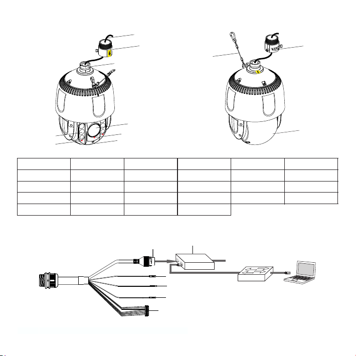
Wall Bracket Mount
Dimensions of wall bracket and the installation sticker
[Note] Hot swapping of the SD card is not recommended. Please format the card during use for the first time.
Please refer to the User Manual for formatting steps.
Unit: mm
② Insert SD card
SD Card Slot
① Unscrew the 4 screws on the
buckled lid and take it down
Micro S D
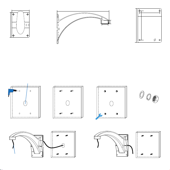
1) Paste the installation sticker onto the wall and drill holes according to the 4 hole marks on the sticker for φ12
expansion screws (hole depth ≥70mm).
If routing cables from the top, a cable outlet hole is needed on the wall. If routing cables from the side of the
device, no need to drill a outlet hole but lead the cables through the U-shaped groove at the side of the base.
2) Insert the M8 expansion screws into the holes (do not screw off the nut) and take off the nuts and spacers when
the expansion screws are fixed tight.
3) Determine wiring method and route cables out. If routing cables from the top, go through the outlet hole on the
wall. If routing cables from the side, go through the U-shaped groove at the bracket base.
Top Cabling
8
① Drill holes by marks on
the sticker
② Insert expansion screws
Cable Outlet
③ Fix expansion screws ④ Take down the
nuts and spacer
Reserve
20~30cm
Base of Bracket
Body of Bracket Installation Sticker
Side cabling
140
200
325
G1½
25
140
118
170
200
12

②Put the spacers onto the expansion
screw bolts, tighten the nuts and fix
the bracket
5) Screw the adaptor into the bracket connector. Bind up the adaptor with thread seal tape and screw it onto the
bracket. Tighten the screws on the bracket and make sure the anti-off screws on the adaptor are loose. Hang
the camera safety hook onto the hanger of the adaptor.
6) Connect cables according to the tags on the wire. Check and sort out the cables and bind the connecting part
with insulating tape. Then pull the cables into the bracket.
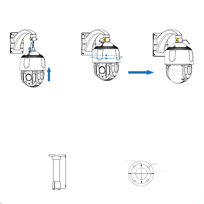
7) Align the straight side of D-shaped head to the yellow sticker on the adaptor, then push the camera till the end
of the adaptor and rotate in pan by 180° until the yellow sticker on the adaptor aligns to that on the connector.
Tighten the 2 anti-off screws on the adaptor.
8) After finishing installation, double check to make sure the dome housing is tight. Peel off the films on the lens
and on the IR light glasses and then power on the device.
①Bind thread seal
tape
②Screw the adaptor into the
connector
③Tighten screws at the connection
part of bracket
Anti-off screws
are loose
④Hang the other side of
safety hook on the adaptor
9
4) Fix bracket. Make the holes on the bracket go through the expansion screw bolts on the wall. Put the spacers
onto the expansion screw bolts and tighten the nuts.
①Insert the expansion screw bolts
into the holes on the bracket and
get the base close to the wall
② Rotate camera by 180° in pan ③ Tighten the anti-off screws
Pendent Bracket Mount
②Custom suspender for working with the pendent bracket must reach the waterproof request without
water penetration or hydrops.
[Note]: ①Pendent bracket is for indoor use and usually not used outdoor. When using it outdoor due to special
requirement, please make sure it meets the waterproof request. Any water penetration failure caused
by poor waterproofness, this company will not be responsible for the risks caused thereof.
10
① Align the straight side of D-shaped head of
camera to the yellow label on the connector,
then push the head till the end of connector
1) Draw holes according to the holes at the base of pendent bracket, drill holes and insert expansion screw bolts.
Dimensions of pendent bracket and the installation sticker
Unit: mm
∅116.5
∅89.5
4-∅10
0.02
245
∅47.4

⑤Make the holes on the bracket base
go through the expansion screws. Put
the spacers on the expansion screws
and tighten the nuts. Fix the bracket.
11
Top Cabling Side Cabling
④Route cables from top or side
2) Route cables according to conditions at the scene, from top or side, and fix the bracket.
3) Bind up the adaptor with thread seal tape and screw it onto the bracket. Tighten the screws on the bracket.
Hang the camera safety hook onto the adaptor.
⑧Hang the safety hook
onto the adaptor
The anti-off screws are loose
⑦Tighten the screws on the bracket
⑥Bind up the adaptor with thread
seal tape and screw it onto the
bracket
①Draw holes
Cable
outlet
②Drill holes and insert
expansion screw bolts
③Fix expansion screw bolts
and and take down nuts and
spacers
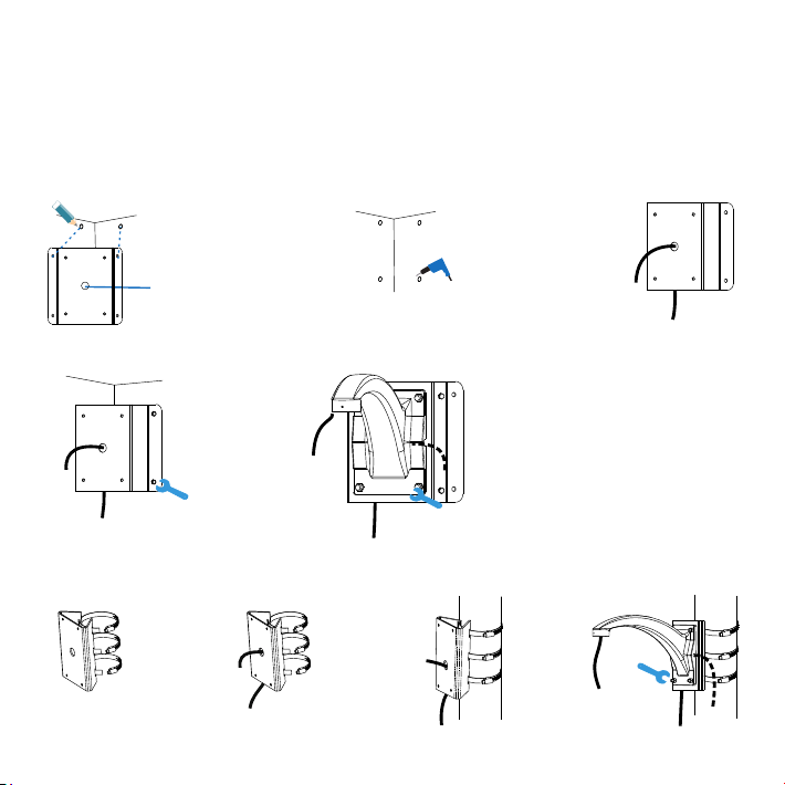
Other Mount Method
Apart from wall bracket mount and pendent bracket mount, there are other methods such as corner bracket
mount and pole bracket mount for installing the dome camera. Their installation steps are shown below (if there
is a bracket adaptor, refer to Step 5 of Wall Bracket Mount). For installation of dome camera, refer to Step 6 to 8
of Wall Bracket Mount.
[Note] All brackets are optional.
③ Thread cables
① Unscrew the clamp
① Draw holes for punching ② Punch holes
⑤ Fix bracket
Cable outlet
② Thread cables ③ Fix pole bracket adaptor ④ Fix bracket
Pole Bracket Mount
Corner Bracket Mount
④ Fix corner bracket apaptor
12
4) For installation of dome camera and cable connection, refer to Step 6 to 8 of Wall Bracket Mount.
13
VII. Login to Client
1. Minimum environment requirements:
ŸProcessor: 3.3 GHz CORE®i2 series or other equivalent processors
ŸRAM Memory: 4GB or above
ŸOperating System: Windows XP or newer version
ŸBrowser: IE7.0 and newer version, Firefox, Google Chrome (41 and lower)
ŸDirectX:9.0c
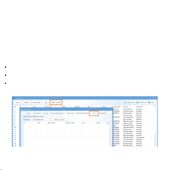
2. Device Activation
When using the device for the first time, run IPCSearch: it will search devices in LAN automatically and display
the list of device IP address, gateway and etc. If the network provides DHCP service, DHCP server will assign
IP for the camera automatically.
Batch: Select the device and click “Batch processing”. In the popup interface, set admin user's password and
the email address to find back the password. Click “Activate” and the camera will reboot.
Individual: Select the device from IPCSearch and right click to select “Active”. Fill admin user name and
password and the e-mail address to find back the password. Click “Activate” and the camera will reboot.
Web client: the device can also be activated through the web client. Set PC and the device in the same network
segment and login to the web. User can set admin password and password reset email on the interface and
click "Activate".

14
3. Modify device IP address
4. Login to the device
1) Double click the device in IPCSearch or click “Login”. Enter user name and password to login the web client.
Click “Modify Params” and set the network parameters. When configuring a static IP for the camera, please
check “Custom device address (Close DHCP)” and fill the Ethernet parameter. During the modification, the
user name (admin) and the password set before activation should be entered. After configuration, the camera
will reboot automatically.
15
2) After login, download and install the plug-in. Close browser during installation.
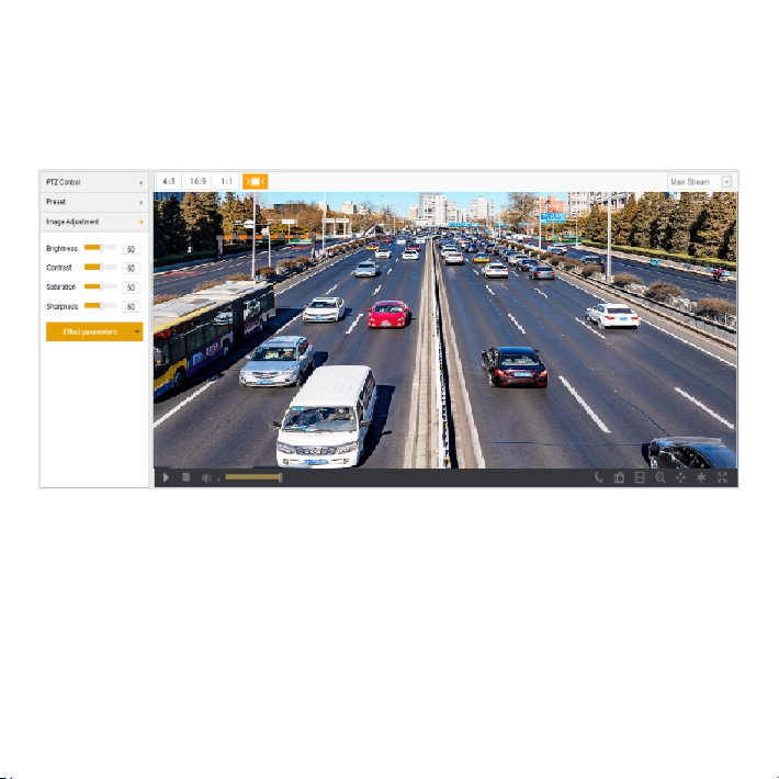
3) Re-login to the web client and view live video directly.
[Note]: Interface of different models may differ. Please subject it to the actual product. Please refer to the Help
file for detailed explanation.
Adjust camera direction, configure camera parameters in web client until the live view meets requirement.
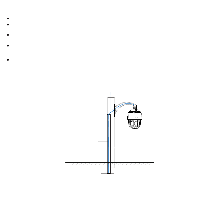
Cement Pole Grounding
16
Earth Lead Resistance≤4Ω
Protective Steel Pipe
Underground 1.5 m
Cement Pole
Power Cord
The camera should be grounded, or ESD may damage the electrical parts.
In thunder and lightning area, camera should be grounded nearby to release the heavy energy of thunder
strike so as to prevent camera from damage.
In area with unstable voltage, camera should be grounded to release the heavy energy of electrical surge so as
to prevent power source from burning.
Camera anti-thunder ground lead cannot replace safety ground lead. When apply poles with imperfect earth,
such as wooden pole and cement pole, camera should connect the safety ground lead to release leak current
so as to ensure the safety of camera or pole.
Camera anti-thunder ground lead must be grounded individually, other than being grounded through other
electrical device nearby.
Metal pole mounting needs PVC pipe to lead the ground wire. Metal pole without lightning rod applies PVC
pipe to lead ground wire. Fix the ground wire near the metal pole and ground it, as the picture shows.
Cement pole mounting needs protective steel pipe to lead the ground wire. As the picture shows, the ground
wire of high speed dome camera goes through the steel pipe and grounds. The Command Center just has to
ground locally according to the norms.
Appendix: Anti-static, Anti-interference, Anti-thunder, Anti-surge
[Metal Pole Ground]
[Cement Pole Ground]

[Note]: If there is middleware installed, such as an optical transceiver or anti-thunder device, the middleware
should be well grounded as well as the camera if the cable goes through the middleware.
17
Metal Pole
Power Cord
PVC Pipe
Lightning Rod
Underground 1.5 m
Video Arrester
Signal Arrester
Power Arrester
45°
The dome camera must be
installed within the 45° angle
range under the lightning rod
Metal Pole Grounding (without lightning rod)
Earth Lead Resistance≤4Ω
PVC Pipe
Earth Lead Resistance≤4Ω
Underground 1.5 m
Metal Pole Grounding (with lightning rod)

V2 20190716
Table of contents
Other Brickcom Digital Camera manuals


