Bridge City HP-6FX User manual

Bridge City
HP-6FX Mini Multi-Plane
HP-6FX 异形刨

English Version
1

HP-6FX Mini Multi-Plane
Congratulations on your purchase of the HP-6FX Mini Multi-Plane. This manual will cover general
setup and operations of the tool, so please carefully read the content of this manual before using
the tool. The manual also includes our warranty and important safety information. As with all tools,
please ensure to take all necessary safety precautions to prevent any accidents! Always remember,
safety first!
SAFETY FIRST
When working with the HP-6FX always remember to:
• Work in a clean and safe environment
• Maintain your tools. A sharp tool is a valuable tool!
• Always make sure to thoroughly clean and maintain your tools.
Overview
HP-6FX Mini Multi-Plane is a specialized hand planing tool for profiling shapes, which can be used
to make shoulder groove, straight groove, V-groove, arc groove and other special shape on the
workpiece surface.
With this HP-6FX Mini Multi-Plane, you can achieve a smooth profile surface without any tear-out,
burr, or other defects.
The profile shape made by HP-6FX Mini Multi-Plane depends on the type of iron used and the
depth of cut.
The four types of irons as listed below are available for HP-6FX Mini Multi-Plane, among which, the
Rabbet Plane Iron is the standard iron, whereas the rest are optional ones.
1. Rabbet Iron 3. Crown Iron
2. V Groove Iron 4. Dado Groove Iron
Note:
1. Each iron is equipped with one specialized front and rear sole.
2. The front sole of Rabbet Iron is equipped with two D-shape scoring cutters; the front sole
of Dado Groove Iron is equipped with one dado scoring cutter.
3. The V Groove Iron and Crown Iron are respectively equipped with specialized hones.
4. Each sole, iron, hone and scoring cutter shall be used as a set, mixed use is not allowed.
2

As shown in Fig.1, the HP-6FX Mini Multi-Plane consists of the plane body, Iron Clamping
Mechanism, Iron Adjustment Mechanism, Rear Sole Locking Mechanism, iron Assembly, Depth
Skids Assembly, and Fence Assembly. The Iron Assembly is interchangeable component, which
allows you to change to achieve different cutting requirements or profile shapes.
Fig. 1 Nomenclature
The plane body, the lead screw, the iron cap, the front tote, and other main parts are CNC
machined stainless steel. The ergonomic arc design is adopted on the rear sole with an overall
polished finish. The handles and knobs are precision polished and PVD coated to achieve
unmatched aesthetic, outstanding ergonomics, and ultra-high corrosion resistance. The depth
skids and fence are CNC machined aluminum alloy. The anodized surface not only provides good
anti-friction and increased hardness, but also an exquisite look.
HP-6FX Mini Multi-Plane is a hand tool that can provide you great pleasure and comfort on the
many projects to come.
Depth Skids Assembly
Iron Adjustment Mechanism
Depth Skids Assembly
Fence Assembly
Iron Assembly
Iron Clamping
Mechanism
Mechanism
Front Tote
Main Body
Rear Sole Locking Wheel
Sole Locking Mechanism
3

Irons
The irons of HP-6FX Mini Multi-Plane are all made of tool steel, which is hardened to a hardness of
RC60-62. They are suitable for cutting all kinds of hardwood and softwood.
As shown in Fig. 2, all the irons must be installed on the 55°bevel of the plane body with iron bevel
downwards and locked by the Iron Clamping Mechanism. The actual cutting angle of the iron is
55°.
18 Sets of iron assemblies are available for HP-6FX Mini Multi-Plane, among which the Rabbet Iron
Assembly is standard part.
The following table shows the Cutting Profiles of the all 18 irons:
No. Name Cutting Parameters Diagram Remark
1 HP-6FX Rabbet Iron With Scoring
Cutter
2 HP-6FX 60° Degree V Groove Iron With Hone
3 HP-6FX 90° Degree V Groove Iron With Hone
Fig. 2 Iron Installation Direction
Cutting Angle
4

Continued table:
No. Name Cutting Parameters Diagram Remark
4 HP-6FX 2mm Radius Crown Iron With Hone
5 HP-6FX 3mm Radius Crown Iron With Hone
6 HP-6FX 4mm Radius Crown Iron With Hone
7 HP-6FX 5mm Radius Crown Iron With Hone
8 HP-6FX 6mm Radius Crown Iron With Hone
9 HP-6FX 30mm Dia. Crown Iron With Hone
10 HP-6FX 40mm Dia. Crown Iron With Hone
11 HP-6FX 50mm Dia. Crown Iron With Hone
12 HP-6FX 2mm Dado Groove Iron With Scoring
Cutter
13 HP-6FX 3mm Dado Groove Iron With Scoring
Cutter
14 HP-6FX 4mm Dado Groove Iron With Scoring
Cutter
5

Retaining Position
Working Position
Continued table:
No. Name Cutting Parameters Diagram Remark
15 HP-6FX 6mm Dado Groove Iron With Scoring
Cutter
16 HP-6FX 8mm Dado Groove Iron With Scoring
Cutter
17 HP-6FX 10mm Dado Groove Iron With Scoring
Cutter
18 HP-6FX 12mm Dado Groove Iron With Scoring
Cutter
Note:
1. Each iron is equipped with hone or scoring cutter, please check the column “Remark”in above
table to confirm the configuration of appropriate irons.
2. Scoring Cutter: it can cut the wood fiber in advance to avoid tear-out and burr. The scoring
cutter must be used with matching iron and sole. It needs to be installed on the front tote. Two
kinds of scoring cutter are available: D-shape scoring cutter (Fig. 3) and dado scoring cutter (Fig.
4).
D-shape Scoring Cutter (Fig. 3)
The two D-shape Scoring Cutters are
only used with the Rabbet Iron. They
are installed on both sides of the front
sole of the rabbet iron, as shown in Fig.
3. In order to use the D-shape scoring
cutter for marking, loosen the retaining
screw and rotate the cutter to where
the flat notch is positioned away from
bottom of the front sole and exposing
the cutting edge. Tighten the retaining
screw and this should allow you to now make scoring marks. If a section of the cutting edge feels
worn, try rotating the D-shape scoring cutter to a sharper section of the cutting edge. Scoring
cutter will need to be replaced if overly worn! (Refer to Fig. 3 – Working Position for reference)
Fig. 3 D-shape Scoring Cutter Installation
6

Fine Tuning Screw
Cutting Depth
Set Screw
When the D-shape Scoring Cutter is not needed, loosen, and rotate the cutter to make the small
flat notch parallel to the bottom of the front sole and secure the retaining screw. When in the
retaining position, the cutting edge should not protrude underneath the sole and should have no
impact when cutting. (Refer to Fig. 3 – Retaining Position for reference)
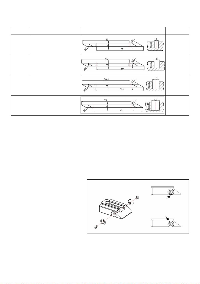
Dado Scoring Cutter (Fig. 4)
The Dado Scoring Cutters is used
with the matching Dado
Groove Irons (2~12mm). The Dado
Scoring Cutter is installed in the slot
of the front sole of the
corresponding iron and tightened
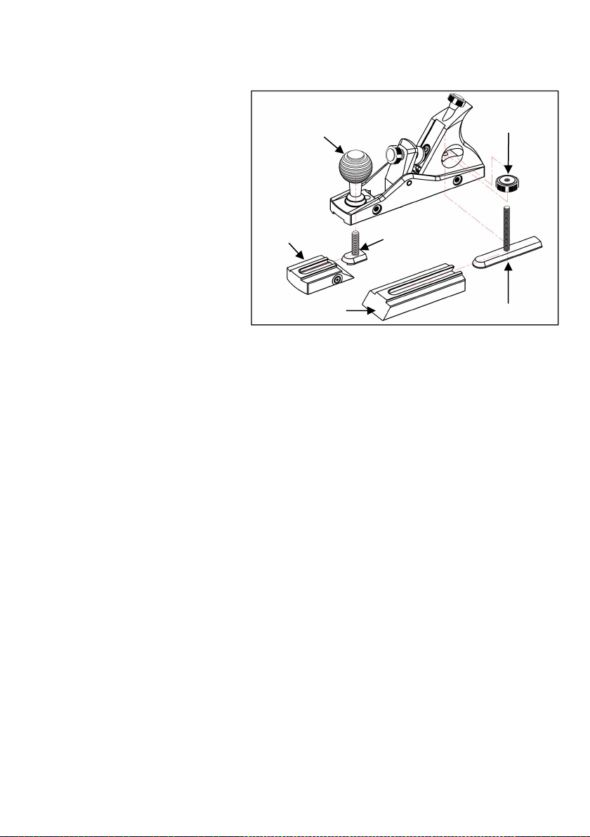
with screws, as shown in Fig. 4.
When adjusting the marking depth,
loosen the screws and move the
Dado Scoring Cutter up and down
to the desired depth. The
fine-tuning screws on the plane
body can be used for additional
smaller adjustment.
After completing all adjustment, tighten the screws to secure the cutter. It is recommended that
the marking depth does not exceed 0.25mm.
Note:The scoring cutter is a special part, if it is worn, you need to replace a new one. To avoid
personal injury, DO NOT ATTEMPT TO HONE OR REPAIR THE SCORING CUTTER. Please reach
out to Bridge City Tool Works customer service to purchase replacement parts.
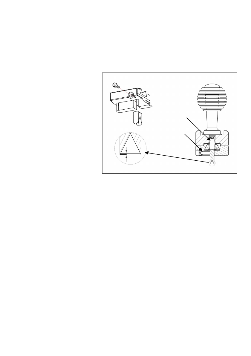
3. The Hone is utilized for the V-Groove Irons and the Crown Irons. It is machined from CNC
aluminum alloy to produce a specific sized V-shape angle and arc. The surface is hardened,
sandblasted, and anodized for an amazing finish. When paired with grinding paste of 6000 mesh
or above, you can achieve a razor-sharp edge on your iron. During the honing process, it is
necessary to ensure that the beveled edge is making complete contact to the honing surface (as
shown in Fig. 5). This is to avoid damaging the iron and hone due to incorrect grinding angle and
direction..
Note: When honing, grinding paste (not included) must be used in conjunction with the hone
to achieve best results.
Fig. 4 Dado Scoring Cutter Installation
7

Clamp Pad
Iron Cap
Iron Ca
p
Knob
Thumb Nut
Iron
Hex Nut
Lead Screw
Multi-Plane Mechanisms Introduction
Iron Clamping Mechanism:
The HP-6FX Mini Multi-Plane follows a
unique Iron Clamping Mechanism by
Bridge City Tool Works, which consists
of the Iron Cap, the Iron Cap Knob and
the Clamp Pad. To secure the iron,
rotate the Iron Cap Knob to secure the
iron at a 55°-degree angle (bevel
facing down) to the plane body.
Iron Adjustment Mechanism:
The Iron Adjustment Mechanism is
used to adjusting the iron cutting
depth. It is installed in the 55° diagonal
hole of the plane body, and consists of
the Lead Screw, the Thumb Nut and the
Hex Nut. The iron can be moved by
rotating the lead screw to adjusting the
cutting depth.
Fig. 6 Iron Clamping Mechanism in the Unlocking Position
Fig. 7 Iron Adjustment Mechanism
Radius Crown Iron and Hone
V Groove Iron and Hone Dia. Crown Iron and Hone
Fig. 5 Honing Guide Diagram
8

Front Tote
Front Sole Dovetail Nut
Rear Sole Dovetail Nut
Rear Sole
Locking Wheel
Front Sole
Rear Sole
Fig. 8 Sole Locking Mechanism
Sole Locking Mechanism:
Multiple soles can be used on the
HP-6FX Mini Multi-Plane, each sole is
fixed to the plane body with the Sole
Locking Mechanism. The Sole Locking
Mechanism consists of the Front Tote,
the Front Sole Dovetail Nut, the Rear
Sole Locking Wheel and the Rear
Sole Dovetail Nut.
The front sole can be removed and
adjusted by loosening the front tote.
The rear sole can be removed and
adjusted by loosening the Rear Sole
Locking Wheel. (Refer to Fig. 8 for reference.)
Depth Skids Assembly and Fence Assembly:
The Depth Skids Assembly consists of a pair of Depth Skids and mounting hardware. It is the
standard auxiliary part provided with the plane, which is used for thickness planing.
The Fence Assembly consists of the fence and the locking parts. It is the standard auxiliary part
provided with the plane, which is used to plane edges to the reference face of your stock.
Please refer to the instructions on page 14-15 for detailed operations of these two auxiliary parts.
9

Operation and Adjustment
Removing and Installing Iron and Sole
Note:
1. The iron is very sharp, please handle with care to prevent accidental injury.
2. While replacing, pay attention to the specifications and names that are laser carved onto
the iron and sole to ensure that they are corresponding/matching.
Iron and Sole Removal:
Refer to Fig. 9 (below), to remove the iron and sole as follows:
①Remove the front sole: Loosen the Front Tote and slide the front sole forward until it is
completely separated from the plane body.
② Loosen the iron cap knob.
③ Remove the clamp pad.
④Remove the iron: Carefully grasp both sides of the iron at the top (near the mounting hole)
with your thumb and index finger, then gently push up to separate the iron from the thumb nut.
Remove the iron from the bottom of the plane body.
⑤ Loosen the rear sole locking wheel and move the rear sole forward until it is completely
detached from the body.
Note: The Rabbet Iron, the V Groove Iron and the Radius Crown Iron are dual-edge irons.
When handling the iron, please be careful to avoid touching the cutting-edge. Irons are very
sharp and can cause accidental injury!
Front Tote
①
②
③
④
⑤
Rear Sole Locking Wheel
Fig. 9 Sequence of Removing the Sole and Iron
Front Sole
Rear Sole
10

Iron and Sole Installation
Refer to Fig. 10 (below) to install the iron and sole as follows:
①Installing the rear sole: Loosen the rear sole locking wheel, install the rear sole onto the rear
sole dovetail nut, which is located underneath the plane body. Slide the rear sole in the direction
indicated by arrow ① in Fig. 10 to the back of plane body until it cannot be slid further. Now the
rear sole should be positioned past the plane body as indicated by the dotted line in Fig. 10.
Temporarily tighten the sole locking wheel to prevent movement while installing the iron.
②Installing the iron: Install the iron with beveled edge downward (please refer to the Fig. 2 for
correct installation angle). Insert the iron through the mounting groove of the plane body at a
55°-degree angle. The iron should be set onto the thumb nut in the appropriate mounting hole
where iron does not protrude too far above/below the plane body.
③ Set the clamp pad onto the iron.
④ Tighten the iron cap knob to lock the iron. Ensure that the locking knob contacts the clamping
pad to properly secure the iron.
⑤Resetting the rear sole: Loosen the rear sole locking wheel, slide the rear sole forward in the
direction indicated by arrow ⑤ in Fig. 10 until it contacts the iron. The rear sole should be
positioned as indicated by the solid line in Fig. 10, which then the rear sole locking wheel should
be retightened to secure the rear sole.
⑥Installing the front sole: Loosen the front tote and engage the front sole with the front
dovetail nut, which is located underneath the plane body. Slide the front sole back in the direction
indicated by the arrow ⑥ in Fig. 10 towards the plane body and tighten the front tote when the
front sole is close to the cutting edge. Remember to leave a small gap to allow shavings to escape
the plane when cutting. Do not completely close the distance between front sole and iron (please
refer to Mouth Adjustment section for more details on page 14).
11

Fig. 10 Sequence of Installing the Sole and Iron
Note: Different irons correspond to different mounting surfaces, as shown in Fig.11. Incorrect
installation position of irons not only fails to lock the irons firmly, but also may cause
personal injury and damage to the plane and workpiece.
Fig. 11 Iron Installation Position
The Rabbet Iron, the V Groove Iron and the Radius Crown Iron are installed in the mounting
groove -- the black solid area shown in above diagram.
The Rabbet Iron and the Dia. Radius Crown Iron are installed on the both sides -- the black solid
sides shown in above diagram.
③
④
⑥①
⑤
②
Front Tote
Rear Sole
Locking Wheel
Iron
Thumb Nut
Iron Mounting Area Iron Mounting Area
12

Lead Screw
Thumb Nut
Cutting Depth
Iron Adjustment
Adjusting cutting depth
The cutting depth of the iron is adjusted
by rotating the lead screw. One full
revolution clockwise will increase the
depth of cut by 0.57mm (0.022”). Vice
versa, decrease the cutting depth by
rotating the lead screw counter
clockwise.
There are five semi-circular cuts milled
around the lead screw knob.
Combined with the knurled sections
between each of the five cuts, the lead
screw becomes a base 10 form to achieve
incredibly small incremental adjustments.
By rotating one of the knurled sections by 36 degrees in either direction (or towards the last
known position of a semi-circular cut next to it) will increase/decrease the cutting depth by
0.05mm (about 0.002”).
Caution: Always be careful to avoid crashing the iron into the front sole. If any interference
occurs, please adjust the iron to ensure parallelism (AVOID CANTED IRON). If needed, open
the mouth to allow room for iron to advance.
There is an assembly clearance between the iron mounting hole and the adjusting nut, When
tuning the cutting depth, the initial rotation of the lead screw will have a slight empty stroke
before it engages, which is perfectly normal.
After adjusting the cutting depth, check the iron position to ensure that it is parallel to the
sole (NOT CANTED OF TO EITHER SIDE).
Fig. 12 Adjusting Cutting Depth
Semi-circular
Cut
13

Mouth Adjustment
As shown in Fig. 13, loosen the front
tote, slide the front sole back and
forth as needed to adjust the mouth
opening. The mouth opening should
be just wide enough to allow shavings
to escape, in order to minimize the
chance of the wood spltting or tearing
out ahead of the cutting.
Depth Skids
The HP-6FX Mini Multi-Plane has a set of Depth Skids. These allow you to create accurate small
pieces of wood that are the same thickness. When used with the rabbet iron, the thickest piece of
wood you could plane is about 7/8”(22mm).
Install the Depth Skids as shown in Fig. 14. (The required hardware is provided in the hardware
box.)
Set up the position of the depth skids as shown in Fig. 15.
The easiest way to set up a hand plane for thickness planing is to use a set of gauge blocks (not
included) which come in 0.001”(0.02mm) increments.
Mouth Opening
Fig. 14 Depth Skids Installation
Fig. 13 Mouth Adjustment
Fig. 15 Set up the Depth Skids Position
Gauge Block
Moving forward and backward
14

Example:
The first step is to plane one face of each of the pieces. For planing a 1/4”(6mm) stock on both
sides, take the 0.255”(6.12mm) and 0.256”(6.10mm) blocks on a smooth clean surface and lay the
lower one under the front sole (avoid contacting with the scoring cutter), and higher one under the
rear sole. Adjust the Depth Skids so they are even on the table surface and lock in place, you
should feel no wobble when the skids are set on a flat surface. Simply plane your stock until the
plane quits cutting.
Fence
The HP-6FX Mini Multi-Plane Fence has a
square face and a 45-degree face. This
allows you to plane edges that are either
square or 45 degrees to the reference face
of your stock.
Install the fence as shown in Fig. 16:
1. Screw the fence post jam nuts to the
fence posts.
2. Install the fence posts to the plane side.
3. Rotate the fence post jam nuts against
the side to lock the fence post in position.
4. Slide the fence onto the fence post and
locate the fence position according to you
work.
5. Rotate the fence locking knobs.
The fence can be attached to either side of the plane body. You can choose to mount the square
side of the fence to plane a perfect square side for a stock or mount the miter side of the fence for
chamfering. The following figure shows the common installation methods.
Fig. 16 Fence Installation
Fence Post Jam Nut
Fence Post
Fence
Fence Lock Knob
Fig. 17 Examples for Fence Guide Planing
15

Iron Honing
The iron included with the HP-6FX Mini Multi-Plane has been precision lapped to a 0.012 RMS
finish. There is no need to lap the back for flatness.
The lapping method for the flat irons (Rabbet Iron and Dado Groove Iron) is the same as that of
conventional irons. The HG-4 Honing Guide of Bridge City is highly recommended to sharpen the
iron if you are not skilled in hand sharpening.
It is recommended to use a hone with the HG-4 Honing Guide. You can also use the grinding paste
of 6000 or more meshes with the HG-4 Honing Guide on a sandblasting and anodized aluminum
alloy surface (Note that the aluminum alloy surface should be flat enough).
Caution: Keep the cutting edge perpendicular to both sides when lapping.
For the irons with dual-edge, one cutting edge of the iron must be protected when it is not
lapped to avoid accidental injury.
For lapping the V Groove Iron and Radius Crown Iron, please refer to the hone instruction on page
7, we recommend using a leather strop to remove any burrs created by sharpening micro-bevels.
Care and Maintenance
Maintenance: After each use, clean the HP-6FX Mini Multi-Plane in time, withdraw the iron to the
bottom of the plane, and put a drop of light oil on the adjusting screw to prevent excessive wear.
Wipe off the abrasive paste, water stains and fingerprints with a soft cloth after each sharpening.
Store: If you plan to store the HP-6FX Mini Multi-Plane for long periods, we recommend you wipe
out the dust from the plane, lubricate all the moving parts and rub off the finger prints and spilled
oil with a clean cloth. Apply protective wax or anti-rust oil on the surface of sole and iron, and store
it in a dry and safe place.
Warranty
All returns, replacements, technical services, and support shall be handled by the distributor’s
customer service organization. If there is a defect on the workmanship of the tool (with no fault of
the customer) within one year from the original date of purchase, please contact the distributor' s
customer service organization and they will determine whether to repair or replace the tool.
16

17

中文版本
18

HP-6FX 异形刨
恭喜您购买了 HP-6FX 异形刨。在使用此款新异形刨之前,请阅读以下使用方法和设置说明。
综述
HP6-FX 异形刨是一款用于对木料进行异形加工的手工工具,可加工肩槽,直槽,V 型槽,圆弧等线性
工件外表面的特殊形状。
正确使用 HP-6FX 异形刨可以加工出无撕裂、无毛边、无震纹等瑕疵的光滑的线性异形表面。
HP6-FX 异形刨加工的异形表面类型依赖于所配刀具的刃口形状和加工深度。
HP-6FX 异形刨适用的刨刀品种有四大类,其中槽口刨刀为标准配件,其余均为选配件:
1. 槽口刨刀 3. 圆弧刨刀
2. V 型刨刀 4. 开槽刨刀
注意:
每款刨刀均配备专用的前、后刨底;
槽口刨刀前刨底配置了 2 只蝶形划线刀,开槽刨刀前刨底配置 1 只对应规格的开槽划线刀;
V 型刨刀和圆弧刨刀配置了对应规格的专用磨刀器;
刨底、刨刀、磨刀器、划线刀必须对应规格配套使用,不可混用。
HP-6FX 异形刨由刨体、刨刀压紧机构、刨刀调节机构、刨底锁紧机构、刨刀组件、深度导向板组件和
靠山组件构成,如图 1 所示。其中刨刀组件为可替换组件,可根据加工需求,成组替换。
刨体、刨刀进给调节螺杆、刨刀压板和锁紧把手等主要零件为不锈钢材质,通过 CNC 加工中心制作而
成,刨体的后侧采用了基于人体工程学的圆弧设计,整体抛光处理。把手、旋钮类零件采用了表面抛光和特
殊的 PVD 涂层处理,兼具无与伦比的美感、手感和超高的耐腐蚀性。刨体两侧的深度导向板和靠山采用铝
合金材质,通过 CNC 加工中心制作,表面阳极氧化处理,既美观,又兼具较高的硬度。
HP-6FX 异形刨是一款可以在使用中获得快乐和舒适体验的手工工具。
19
Table of contents
Other Bridge City Power Tools manuals
Popular Power Tools manuals by other brands

Chef's Choice
Chef's Choice EdgeSelect 120 instructions

easymaxx
easymaxx JD3362 operating instructions

CO/Tech
CO/Tech Q1B-Mz-2000-UK instruction manual

Power Fist
Power Fist 8344103 user manual

Chef's Choice
Chef's Choice Diamond Hone 325 instruction manual

Gema
Gema OptiGun GA03-E Operating instructions and spare parts list

Chef's Choice
Chef's Choice EdgeSelect Diamond Hone 120 instructions

Unimax
Unimax S-2 5A Translation of the original manual

ProWorld
ProWorld TRANSPRO SEMI-AUTO CAP user guide

PowerLite
PowerLite MAX HN65S Operating instructions manual

Bosch
Bosch GSR 10,8 V-LI Professional Original instructions

Senco
Senco SCN55S operating instructions