Bridge City HP-9v2 User manual

BRIDGE CITY TOOL WORKS
Bridge City HP-9v2
Dual Angle
Block Plane
Quality is contagious


ENGLISH VERSION


Fig. 1: Nomenclature
IronClamping
Mechanism
IronAdjustment
Mechanism
Depth Skids
Assembly
Fence
Assembly
Main Body
Iron
HP-9v2 Dual Angle Block Plane
Congratulations on your purchase of the HP-9v2 Dual Angle Block
Plane. Please read the following general usage and set-up notes prior
to using your new plane.
Overview
The HP-9v2 Dual Angle Plane is a “bevel up” plane. This means that
the iron bevel is visible from the top of the plane when bedded. The
iron bed of the HP-9v2 plane is pitched 12° from the bottom (or “sole”)
of the plane.
The sole and adjustable throat plate are solid stainless steel, and the
anodized aluminum sides are pinned to the sole and retained by
screws. Do not attempt to remove the sides, they will not separate
from the sole with the screws removed. The iron clamping is achieved
by a four-linkage mechanism. These components are CNC machined
from solid aluminum and anodized creating a beautiful finish that is
almost as hard as a diamond.

Fig. 2: Iron Geometry
Fig. 3: Cutting Angle Geometry
The plane sides have been “skeletonized” creating a harmonious
design that differs greatly in appearance from the traditional block
planes based upon early European designs. The HP-9v2 Dual Angle
Block Plane is truly a unique and fun-to-use tool that will meet the
needs of the most demanding users.
The Iron
The HP-9v2 Dual Angle Block Plane features an A2 tool steel iron which
has been hardened to Rockwell 60-62. A2 is an air-hardened tool steel
which contains a small percentage of chromium and molybdenum for
added durability in cutting hard or soft woods.
The supplied iron features bevels of 30° (25° primary bevel with a 5°
micro-bevel) and 35° (30° primary bevel with a 5° micro-bevel). The
lower angle bevel is longer than the higher angle bevel, this will help
you to determine which angle you are using by sight.
When the iron is bedded at 12°, the effective attack angles are either
42° or 47°.

Fig. 4: Iron Clamping Mechanism in the Unlocking Position
The 42° low attack angle is preferable when planing end grain and for
straight grained woods. The higher 47°attack angle (35° plus 12°
degrees) is typically used for hardwoods. Feel free to experiment!
Sharpening
A honing guide is highly recommended to sharpen the iron if you are
not skilled in hand sharpening. Always use the magnetic iron guard on
the end not being sharpened to prevent accidental injury.
The iron included with the HP-9v2 Dual Angle Block Plane has been
precision lapped to a .5 RMS finish. A typical glass mirror is a .5 RMS.
There is no need to lap the back for flatness.
We recommend using a leather strop to remove any burrs created by
sharpening micro-bevels. Lapping the back of the iron on a sharpening
stone will produce scratches that degrade the factory lap.
The Iron Clamping Mechanism
The HP-9v2 Dual Angle Block Plane features a unique, non-traditional
iron clamping system. It is important to understand how to adjust this
mechanism without damaging the plane body or components.

The iron clamping mechanism is controlled by the polished cap. When
raising the cap, the clamp arm lifts out of the way unlocking the iron
for removal. Moving the cap downward until it snaps will tighten the
iron.
Bevel up irons only need a small amount of pressure to keep the iron
bedded without chatter during cutting. When the iron clamping is
properly adjusted, the iron clamping mechanism will allow for both
iron cant and depth adjustment without unlocking the mechanism.
The iron clamping mechanism is adjusted at the factory. If it needs
adjusting, please follow the steps below to prevent damaging the
plane:
1.Pull up the cap to lift the clamp arm.
2.Turning the iron clamping knob counter-clockwise to fully loosen
the iron clamping.
3.Install a iron into the plane body and push down the cap as far as it
will go.
4.Turn the iron clamping knob clockwise until you first feel resistance.
5.An additional quarter turn of the iron clamping knob will tighten
against the iron. Additional quarter turns may be required to achieve
the optimal tightness which does not allow the iron to cant, or shift in
use.
DO NOT OVERTIGHTEN THIS MECHANISM AS YOU CAN DAMAGE THE
CLAMP ARM.
A bent clamp arm is a sure indication that the tool has been abused
and is not covered by warranty.
Iron Removal and Installation
CAUTION: The iron is sharp, take care when handling the iron to
prevent serious injury.

Please follow the steps below to remove the iron:
1.Fully open the mouth by loosening the front tote and sliding the
throat plate all the way forward and tighten. This helps to prevent
nicking the iron on the throat plate.
2.Lift the cap until the clamping mechanism is raised to its highest
position.
3.Hold the plane in one hand with your hand on top and your index
finger on the iron. Turn the plane upside down and the iron can be
safely removed as you allow it to drop into your palm.
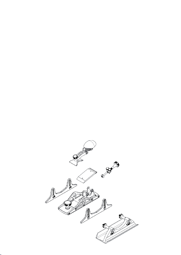
Please follow the steps below to install the iron:
1.Mount the magnetic iron guard on the end that will not be used.
2.Insert the iron by introducing the protected end first.
3.Slowly lower the iron onto the index pin.
4.Push down the cap to tighten the iron.
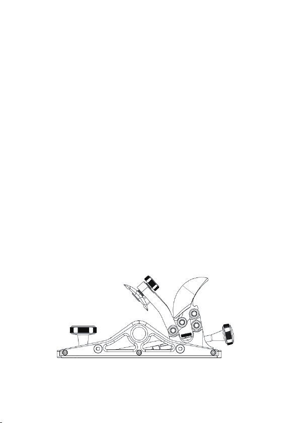
Iron Adjustment
Both cutting depth and cant (iron angle) can be adjusted by the lead
screw under the cap. However, in use we find it much easier to adjust
the cant of the iron with your index fingers through the pockets in the
plane sides.
Adjusting Cutting Depth
The lead screw has 2 threads per millimeter. One full revolution
clockwise will increase the depth of cut by 0.1mm (0.004”). Decrease
the cut depth by rotating the lead screw counter clockwise.
There are five semi-circular cuts milled around the lead screw knob.
These serve two purposes, it is easy to grip and combined with the
knurled sections between each of the five cuts, the lead screw
becomes a base 10 form to achieve incredibly small incremental
adjustments.

Fig. 5 Adjusting Cut Depth
Fig. 6: Adjusting Iron Cant
CAUTION: Always be careful to avoid crashing the iron into the
throat plate.
Adjusting Iron Cant
The cutting edge of the iron is typically canted for two purposes; to
create uniform shaving thickness or to create a non-uniformed shaving
thickness. The former is needed to correct for sharpening error, and
the later to compensate for the tendency of the shaving to be heavy on
the operator side of stock.
To cant the iron, flip the plane to a sole-up position, move the lead
screw side to side, then sight along the sole to check if the setting is
correct for you. You may find however it is easier and more precise to
adjust the cant by using your index fingers through the cutouts in the
plane sides.
Iron Depth
Rotating one knurled section to one of the semi-circular cuts next to it
will increase/decrease the cut depth by 0.01mm.

Fig. 7: Mouth Adjustment
Fig. 8: Backlash Adjustment Screw Knobs
Backlash
Adjustment
Screw Knobs
Mouth Adjustment
The mouth opening is adjusted by loosening the front knob and
moving the throat plate forward and backward. Take care not to hit the
iron with the throat plate.
The mouth opening should be just wide enough to allow shavings to
escape, in order to minimize the chance of the wood splitting or
tearing out ahead of the cutting. When adjusting the mouth opening,
consider the added opening amount required if you plan to cant the
iron to cut heavy on one side.
Backlash Adjustment
The backlash of the lead screw is minimized by adjusting the two
screw knobs located on the top of the brass lead screw pivot.

Fig. 9: Brass Lead Screw Pivot
Fig. 10: HP-9v2 Dual Angle Block Plane with Depth Skids
Brass Lead
Screw Pivot
Rotate the screw knobs to tighten the brass lead screw pivot to
eliminate the possibility of the lead screw shifting backward. After
adjusting these screw knobs, ensure that the top half of the brass lead
screw is level with the respect to the bottom half. The lead screw
should feel precise and work smoothly without binding.
Depth Skids
The HP-9v2 Dual Angle Block Plane has a set of Depth Skids. These
allow you to create accurate small pieces of wood that are the same
thickness. The thickest piece of wood you could plane is 1-1/4” (about
32mm).

Fig.11:Depth Skids Installation
Attach the Depth Skids with the provided screws and washers. A
washer goes between the screw head and Depth Skid. Then mount the
Depth Skid sets to the sides with spacers in between.
The easiest way to set up a hand plane for thickness planing is to use a
set of Pin Gauges which come in .001” (0.01mm) increments.
The first step is to plane one face of each of the pieces. For planing a
1/4” (6mm) stock on both sides, take the .260” (6.22mm) and .261”
(6.20mm) pins on a smooth clean surface and lay the lower one under
the nose of the plane, and higher one under the back. Adjust the Depth
Skids so they are even on the table surface and lock in place, you
should feel no wobble when the skids are set on a flat surface. Simply
plane your stock until the plane quits cutting. Depending on how far
your iron is protruding you may need to adjust the pin gages to get the
exact size you need.

Fig. 12: Fence Installation
Fence
The HP-9v2 Dual Angle Block Plane Fence has a square face and a
45-degree face. This allows you to plane edges that are either square
or 45 degrees to the reference face of your stock.
Attach the fence with provided fence posts and jam nuts, the hex
locking studs and locking knobs are pre-installed in the fence.
Please follow the steps below to mount the fence:
1
.
Screw the jam nuts to the fence posts.
2
.
Install the fence posts to the plane side.
3
.
Rotate the jam nuts against the side to lock the fence post in
position.
4
.
Slide the fence onto the fence post and locate the fence position
according to your work.
5
.
Rotate the fence locking knobs.

Fig. 13: Examples for Fence Guide Planing
The fence can be attached to either side of the plane body. You can
choose to mount the square side of the fence to plane a perfect square
side for a stock or mount the miter side of the fence for chamfering.

Care and Maintenance
Iron: Apply a light coat of thin oil or WD-40 on the iron if the iron will
be stored for long periods of time or in high-humidity locations. Wipe
the iron clean of finger prints with a clean cloth after each sharpening.
Sole: Wipe a thin coat of quality wax or paraffin on the sole prior to
each session.
Iron Adjustment Mechanism: Apply one drop of light machine oil in
the top of the lead screw and the index pin that fits inside the iron
once a year or upon the frequency of use to prevent premature wear.
Wipe a thin coat of quality wax on the surface of the brass lead screw
pivot to prevent the brass part from getting oxidization.
Store: If you plan to store the HP-9v2 block plane for long periods, we
recommend you wipe out the dust from the plane, lubricate all the
moving parts and rub off the finger prints and spilled oil with a clean
cloth. Put the plane in the included micro-fiber plane sock and store in
a safe place.
Warranty
All returns, replacements, technical services, and support shall be
handled by the distributor’s customer service organization.
If there is a defect on the workmanship of the tool (with no fault of the
customer) within one year from the original date of purchase, please
contact the distributor’s customer service organization and they will
determine whether to repair or replace the tool.

Package Contains
Plane body with all integrated components
42/27 Dual Edge Iron
Magnetic blade guard
Two Depth Skids and components
Guide Fence and components
Plane sock
Instruction Manual

中文版本

图 1: 术语
刨刀压紧机构
刨刀调节机构
深度导向板
组件
靠山组件
本体
刨刀
HP-9v2 双角度短刨
恭喜您购买了 HP-9v2 双角度短刨。在使用新短刨之前,请阅读以下使用方法和
设置说明。
综述
HP-9v2 双角度短刨是一款刨刀正装的木工刨。这意味着安装刨刀后,可以从上
方观察到刨刀的斜面。刨刀安装在与刨底呈 12° 的刨刀基座中。
刨底和可调节的喉板使用不锈钢材质制作,两侧的侧边通过固定销与刨底连,
并且使用螺丝锁紧。不要尝试取下刨身的侧边, 拧松螺丝后也无法拆除刨身侧
边。刨刀通过四连杆结构压紧。这些部件使用铝材通过 CNC 加工中心制作,表
面通过阳极氧化处理非常美观,并且几乎与钻石硬度相同。

图 2:刨刀角度几何图示
图 3:刨削角几何图示
刨身的侧边简化设计后获得了优美的设计,这与传统的根据欧洲早期设计改
良的短刨外观有明显的不同。HP-9v2 双角度短刨真正是一款独特的,并且可
以让大多数使用者在使用中获得快乐的短刨。
刨刀
HP-9v2 双角度刨刀配有一把工具钢刨刀,通过硬化处理达到洛氏硬度 60-62。
工具钢通过气冷硬化,并且含有铬、钼和钨用于增加硬度,更加适合硬木和软
木。
刨刀两端分别有一个刃口。一端为 30°(25°主斜面与 5 度微角); 另一端为
35°(30°主斜面与 5°微角)。角度较低的刃口斜面比角度较高的稍长一些,这可
以帮助你快速判断刃口角度。
当刨刀安装在 12°的基座内,实际的刨削角度为 42°与 47°。
42°的刨削角更适合用于刨削端面纹理和直纹纹理。更高的 47° 刨削角则更适
合用于硬木刨削。你可以根据自己的习惯尝试新的角度。
Other manuals for HP-9v2
2
Table of contents
Other Bridge City Power Tools manuals
Popular Power Tools manuals by other brands

Chef's Choice
Chef's Choice EdgeSelect 120 instructions

easymaxx
easymaxx JD3362 operating instructions

CO/Tech
CO/Tech Q1B-Mz-2000-UK instruction manual

Power Fist
Power Fist 8344103 user manual

Chef's Choice
Chef's Choice Diamond Hone 325 instruction manual

Gema
Gema OptiGun GA03-E Operating instructions and spare parts list

Chef's Choice
Chef's Choice EdgeSelect Diamond Hone 120 instructions

Unimax
Unimax S-2 5A Translation of the original manual

ProWorld
ProWorld TRANSPRO SEMI-AUTO CAP user guide

PowerLite
PowerLite MAX HN65S Operating instructions manual

Bosch
Bosch GSR 10,8 V-LI Professional Original instructions

Senco
Senco SCN55S operating instructions