Brigantia 24-DVRS25NB-2 Owner's manual

200-0324-07
July 11 2019
24-DVRS25NB-2
24-DVRS25NBN-2
Direct Vent Gas Fireplace
Heater
USERS’ INSTALLATION
OPERATION and
MAINTENANCE MANUAL
INSTALLER: Leave this manual with the appliance.
CONSUMER: Retain this manual for future reference.
- Do not store or use gasoline or other ammable vapors or
liquids in the vicinity of this or any other appliance.
- WHAT TO DO IF YOU SMELL GAS:
• Do not try to light any appliance
• Do not touch any electrical switch; do not use any
phone in your building
• Leave the building immediately
• Immediately call your gas supplier from a
neighbor's phone. Follow the gas suppliers
instrucons
• If you can not reach your gas supplier, call the re
department
- Installaon and service must be performed by a qualied
installer, service agency or the gas supplier.
This appliance may be installed in an aftermarket
permanently located, manufactured home (USA
only) or mobile home, where not prohibited by
local codes.
This appliance is only for use with the type
of gas indicated on the rating plate. This
appliance is not convertible for use with other
gases, unless a certified kit is used.
WARNING: If the information in this manual is
not followed exactly, a fire or explosion may
result causing property damage, personal
injury or loss of life.
SERIAL NUMBERS 300308 AND HIGHER
Gas Fireplace Efficiency Rating
74.96%
Based on CSA P.4.1-15
Archgard Fireplace Products
7116 Beatty Dr
Mission, BC V2V 6B4
Canada

TABLE OF CONTENTS
Rating Plate 4
Caution and Safety Instructions 6
Appliance Certification, Installation Codes and Specifications 7
Appliance Dimensions and Framing Dimensions 8
Installation Instructions 9 - 11
Clearance to Combustibles, Mantle Clearances, Nailing Flanges 12
Venting Instructions 13 - 17
Wiring Schematics 18
Gas Connections 19
Checking Inlet/Outlet gas pressures, Adjusting Pilot and Convertible Pilot Orifice 20
Contemporary Panels 21
Component Removal - Door Removal, Surround Clip Installation 22
Safety Barrier Installation 23
Final Installation Check and Initial Operation 24
Lighting Instructions on Rating Plate 25
First Fire and Lighting Instructions (CAUTION) 26
Dynamic Start Advantage 27
Remote Control Setup and Operation 28 - 35
Maintenance and Cleaning the Appliance 36
Conversion Kit Instructions 37 - 39
Replacement Parts List 40
Frequently Asked Questions 41
Warranty 42
Warranty Registration Card 43

INTRODUCTION
Congratulations on choosing an Brigantia fireplace!
The 24-DVRS25NB(N)-2 is one of the most advanced direct vent fireplace heaters available. It
is solidly designed using the latest technology and manufactured to the highest quality. It is our
aim to provide you with an appliance for many trouble-free years of reliable service.
The following are just some of the many features of your new gas fireplace:
CPI vs IPI:
Continuous Pilot on Demand Ignition (CPI): In this mode the pilot runs continuously even when the
main burner is off. The Continuous Pilot on Demand Ignition operates on a seven day cycle. If the main
burner is not turned on for seven continuous days, the pilot will turn itself off. When the main burner is lit
again the cycle repeats. The pilot will remain lit for seven days, even after the main burner is turned off.
If the main burner is lit during a seven day timing cycle, the seven day timer will reset.
Intermittent Pilot Ignition (IPI): A fuel saving mode in which the pilot is only used when the main
burner is on.
This appliance is shipped in IPI mode. IPI mode is often the preferred method, however, there are some situations
where it may be preferable to switch the fireplace into CPI mode. For example, in colder climates the glass door or
the front of the fireplace could become very cold to the touch. Dynamic Start Advantage will solve most problems
experienced by older IPI operated fireplaces.
Please complete and submit the warranty registration card included in the back of this manual or
by visiting us at:
www.archgard.com/warranty-registration
Heater Classification The 24-DVRS25NB(N)-2 is classified as a heating appliance. In
conjunction with an optional thermostat, it can be operated
continuously for zone heating.
High Efficiency The 24-DVRS25NB(N)-2 has one of the highest efficiencies of
any fireplace, which means that it is less expensive to operate.
Adjustable Flame The flame aesthetics and heat output can be adjusted to suit
your heating needs.
Solid Construction The 24-DVRS25NB(N)-2 is constructed mainly of 14 and 18
gauge galvanized and aluminized steel for long life and
durability.
Electronic Control System This fireplace comes standard with the Dynamic Start Ad-
vantage. This new electronic ignition system is the latest in fire-
place technology. It helps to create a better draft, better flame
appearance, less condensation on the glass, and years of care-
free operation. See Page 27 for complete explanation of how
the system works.
Multiple Electronic Pilot
Settings
This fireplace uses a gas control valve that is operated by a
Multifunction Remote Control. It can be set up as either an In-
termittent Pilot Ignition (IPI) system, or Continuous Pilot on De-
mand Ignition (CPI) system (also known as a Pilot on Demand
(POD)).

24-DVRS25NB(N)-2 4
RATING PLATE

24-DVRS25NB(N)-2 5
Installaon Checklist
This standard installaon checklist is to be used by the installer in conjuncon with, not instead of, the instrucons contained
within this installaon manual.
Customer: Date Installed:
Install Address: Locaon of Fireplace:
Installer:
Appliance Install: YES IF NO, WHY NOT?
Standos and side nailing anges are installed.
Fireplace is leveled and secured.
Venng: YES IF NO, WHY NOT?
Venng conguraon complies with vent diagrams.
Venng installed and secured in place maintaining proper clearances.
Maintained 1/4" rise for every 1 . on horizontal run.
Terminaons installed and sealed in compliance with local building code.
Direct vent terminaon is highest point in vent assembly.
Wiring / Electrical: YES IF NO, WHY NOT?
Connected to household 110/120v per local codes.
Unit is properly grounded.
Gas: YES IF NO, WHY NOT?
Proper appliance for fuel type?
Was a conversion performed?
Leak check performed & inlet and manifold pressures veried?
Veried proper air shuer seng?
Finishing YES IF NO, WHY NOT?
Only noncombusble material installed in noncombusble areas.
Clearances meet installaon manual requirements.
Mantels and/or projecons comply with install manual.
Appliance Setup: YES IF NO, WHY NOT?
Burner media / log set, glass door, and screen installed according to manual
Manual given to home owner.
Did you check ame modulaon?
Comments:

24-DVRS25NB(N)-2 6
Safety Informaon
Cauon
FOR YOUR SAFETY - Do not install or operate your 24-DVRS25NB(N)-2 without reading and understanding this
manual. Any installation or operational deviation from this instruction manual voids the warranty and may prove haz-
ardous.
• This appliance must be installed by a qualified gas installer and the installation must conform to the installation
codes
• Provide adequate clearance around air openings into combustion chamber
• Never obstruct front openings
• Provide adequate clearances for proper operation and servicing of the appliance
• This appliance must be properly connected to an approved venting system and must not be connected to a chim-
ney flue serving a separate solid fuel burning appliance
• Flow of combustion and ventilation air must not be obstructed - always provide adequate combustion and ventila-
tion air
• Always provide adequate clearance around the intake and exhaust openings
Safety
• Due to high temperatures, the appliance should be located out of traffic and away from furniture and draperies
• Children and adults should be alerted to the hazards of high surface temperature and stay away to avoid burns or
clothing ignition
• If this appliance is installed directly on carpeting, tile, or other combustible material other than wood flooring, the
appliance shall be installed on a metal or wood panel extending the full width and depth of the appliance
• Young children should be carefully supervised when they are in the same room as the appliance. Toddlers, young
children and others may be susceptible to accidental contact burns. A physical barrier is recommended if there
are at risk individuals in the house. To restrict access to a fireplace or stove, install an adjustable safety gate to
keep toddlers, young children and other at risk individuals out of the room and away from hot surfaces
• Do not store or place combustibles, gasoline, and other flammable vapors and liquids near the appliance
• Clothing or other flammable material should not be placed on or near the appliance
• WARNING: Do not operate appliance with the glass front removed, cracked, or broken. Removal of the glass
should be done by a licensed or qualified service person. Do not to strike or slam the glass
• Any safety screen or guard removed for servicing an appliance must be replaced prior to operating
• Installation and Repair should be done by a qualified service person. The appliance should be inspected before
use and at least annually by a professional service person. More frequent cleaning may be required due to exces-
sive lint from carpeting, bedding materials, etc. It is imperative that the control compartments, burners and circu-
lating air passageways of the appliance are kept clean
• Under no circumstances should any solid fuel (wood, coal, paper or cardboard, etc.) be used in this appliance
• Keep burner and control compartment clean
• Do not use this appliance if any part has been under water. Immediately call a qualified service technician to in-
spect the appliance and to replace any part of the control system and any gas control which has been under wa-
ter
• California Proposition 65 Warning: This product can expose you to chemicals including Carbon Monoxide,
that is an externally vented by-product of fuel combustion, which is [are] known to the State of California to cause
cancer, birth defects, or other reproductive harm. For more information, visit www.P65Warnings.ca.gov.
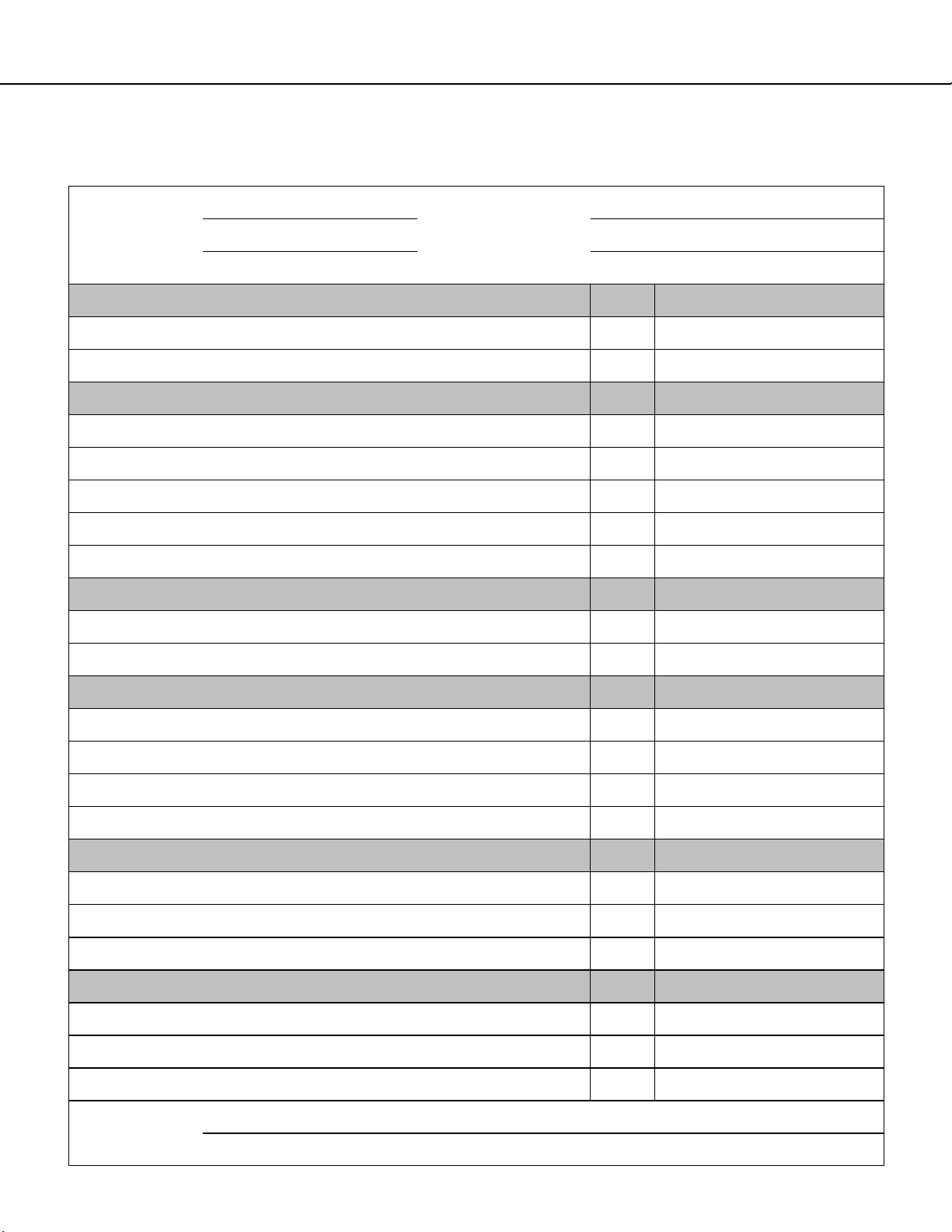
Each Archgard Gas Fireplace is checked and tested at the factory prior to being packaged and shipped to our dealers
and finally installed in your home. Before leaving this unit with the customer, the installer must ensure that the appli-
ance is firing correctly and that the electrical system is in working order. The Installation Checklist should be used to
ensure the proper installation of this gas fireplace heater and to document any deviations from a typical install.
Any alteraon to the product that causes carbon or soot deposits that results in any damage or requires cleaning is not the
responsibility of the manufacturer.

24-DVRS25NB(N)-2 7
This appliance was listed by QAI Laboratories Inc to the following USA and Canadian gas
appliance standards.
- ANSI Z21.88-2009/CSA 2.33-2009 Vented Gas Fireplace Heaters
- CAN/CGA-2.17-M91(R2009) Gas-Fired Appliances for Use at High Altitudes
- CSA P.4.1-15 Testing method for measuring annual fireplace efficiency.
- CSA C22.2 No.3 – M1988(R.2014) – Electrical Features of Fuel-Burning Equipment
Commonwealth of Massachusetts: This appliance has been manufactured in accordance
with Massachusetts code 248 CMR 5.00.
Approval Code: G1-0319-387 . (http://license.reg.state.ma.us/public/licque.asp).
Please contact Archgard Industries Ltd., if you have any questions regarding the certification of
this appliance.
APPLIANCE CERTIFICATION
INSTALLATION CODES
This appliance must be installed by a qualified gas appliance installer. The installation must
conform with the local codes or, in the absence of local codes, with the current National Fuel
Gas Code ANSI Z223.1/ NFPA 54 in the US, or Installation Code CAN/CGA-B149.1 in Canada.
Electrical connections and grounding must conform with local code, or current National
Electrical code ANSI/NFPA No. 70-1987 in the US, and in Canada the current Canadian
Electrical Code CSA C22.1.
We recommend that our gas hearth products be installed and serviced by professionals
who are certified in the U.S. by the National Fireplace Institute®(NFI) as NFI Gas
Specialists.
HIGH ALTITUDE INSTALLATION
When installing this appliance beyond 4500 ft. (1372 M) above sea level, the appliance must
be properly de-rated and installed according to local codes, in the absence of local codes, with
the current National Fuel Gas Code, ANSI Z223.1/ NFPA 54, in the US or Installation Code,
CAN/CGA-B149, in Canada.
Natural Gas (NG) Propane (LP)
Manifold Pressure 1.1 - 3.8 in. W.C. (0.3 - 0.9 kPa) 2.9 - 11.0 in. W.C. (0.7 - 2.7 kPa)
Min. Supply Pressure
Max Supply Pressure
5.0 in. W.C. (1.2 kPa)
14.0 in. W.C. (3.5 kPa)
12.0 in. W.C. (2.98 kPa)
14.0 in. W.C. (3.5 kPa)
Orifice Size #43 DMS (2.26 mm dia) #54 DMS (1.397 mm dia)
Nominal Input Rating 14,000 - 25,000 BTU/hr
(4.4- 9.1kW)
14,000 - 25,000 BTU/hr
(4.4 -9.1kW)
P.4 Fireplace Efficiency (FE) 74.96% 74.96%
P.4 Steady State Efficiency 75.67% 75.67%
Electrical Rating 120 VAC, 60Hz less than 2 A. 120 VAC, 60Hz less than 2 A.
Gas Control SIT 885 Proflame II Dynamic Start Advantage with Continuous Pilot
on Demand
Altitude 0 - 4,500 ft. (0 - 1372 M) 0 - 4,500 ft. (0 - 1372 M)
Primary Air Opening 1/4” (6 mm) OPEN FULLY OPEN
SPECIFICATIONS

24-DVRS25NB(N)-2 8
APPLIANCE DIMENSIONS
Surround Installed
Surround Removed

24-DVRS25NB(N)-2 9
39 1/2”
1003 mm
11”
280 mm
26 1/2”
10”
254 mm
Framing Dimensions
The following section describes in detail
the requirements for framing for the
model 24-DVRS25NB(N)-2.
Note: Framing should be constructed
as required by local building codes
Construct the opening
to dimensions shown:
26 1/2” wide x 39 1/2”
high X 5 1/2” deep
The bottom of the
frame must be min 4”
up from combustible
floor
Installation Instructions
When installing on an exterior wall you must
include the exterior wall insulation and termi-
nation kit. Place insulation board with the foil
facing in to the room as shown in figure 3
Frame hole out opening and cut out hole for
the termination and thimble as shown in fig-
ure 1 and 2.
Figure 2
Figure 1
Figure 3
20”
508 mm
4”
102 mm
Minimum Distance to a
Combustible Floor

24-DVRS25NB(N)-2 10
Installation Instructions Cont.
Install the inside portion of the wall thimble and
seal the entire inside with a high temperature sili-
cone sealant. This is critical to prevent cold
drafts. See figure 4
Figure 4
Install the nailing flanges provide by screwing
them to the side of the outer shell using the hole
required for the facing material. Then place the
fireplace into the framed opening and nail or
screw the nailing flanges to the wall.
Figure 5
Go to the outside and caulk the vent
collar and firestop to prevent cold
drafts. See figure 6.
Install the termination.
Figure 6
SEAL

24-DVRS25NB(N)-2 11
Installation Instructions
Outside wall installation example
The Brigantia 24-DVRS25NB(N)-2 requires 120V for the operating system. There is a factory installed
electrical box to accommodate the connections. (see wiring diagram pg. 18)
The fireplace comes complete with a battery back-up system that will operate the fireplace for a limited
time in the event of a power outage.
The 120V circuit must be electrically grounded in accordance with the local codes or, in absence of local
codes, with the National Electrical Code ANSI/NFPA 70, or the Canadian Electrical Code CSA C22.1.
Electrical Requirements
Secure sidewall termination to fireplace
with Milpac (DO NOT use silicone) on
both inner exhaust and outer supply air
pipes. Once installed on the unit se-
cure the termination to the wall with
screws to each corner.
Horizontal termination 999-DV-HTCL is to be used for direct connection to the unit. If extending
the vent using flex, a change to the 999-DV-HTC is required.

24-DVRS25NB(N)-2 12
Inches mm
Top - to standoffs 0” 0
Sides-to standoffs 0” 0
Adjacent Side Wall 9” 227
Room Floor*
(From bottom of
fireplace shell)
4” 101
Vent - Top 2” 50
Vent - side/bottom 1” 25
Front 48” 1210
Room Ceiling*
(From Top of Door) 24” 609.6
Minimum measurements below are from the edge
of door (unless otherwise noted).
Clearance to Combustibles
* Clearance to combustible floor
must maintain clearances from the
top surface of carpet, flooring, etc.
Nailing Flanges
Install the nailing flanges provided, by screwing them to the side of the outer shell using the appropriate holes for the facing
material. Place the fireplace into the framed opening and secure the nailing flanges to the wall.
Mantle Clearances
Top of Door
24.00in
[609.6mm]
Room Ceiling

24-DVRS25NB(N)-2 13
Installation Instructions Cont.
VENTING
Clearance to combustibles
The following clearances must be maintained around the vent pipe:
Vertical runs: 1”
Horizontal runs: 2” on top, 1” sides and bottom
IMPORTANT: This appliance venting system is a sealed system (DV), which means that all combus-
tion air is supplied from outdoors and the combustion products are exhausted to the outdoors.
Note: Only venting systems listed in this manual may be used.
Planning your vent installation
This type of direct vent system may terminate in one of two ways: vertical termination using a vent cap,
or horizontally using a wall termination. There are limitations to the vertical and/or horizontal length.
Note: As this system is a sealed system,
The female section of the pipe/fitting has four indentations evenly spaced around the pipe. These indentations are
designed to slide over the male section of the pipe and fully lock by a clockwise quarter turn.
Vent Restrictors
Due to the extra flow produced by tall venting con-
figurations the vent restrictors must be adjusted to
maintain performance. The vent restrictor is de-
signed into the appliance firebox.
When required, adjust the restrictor inside the unit
firebox. Release the screws and adjust the restrictor
position according to the venting charts
LISTED VENTING SYSTEMS
The listed chimney vent systems uses a twist lock connection. Assemble the vent system using the de-
sired combination of sections and elbows for your installation. Make sure you fully insert and twist the
mating sections all the way to make a solid connection.
Dura vent Selkirk
Ameri-vent ICC
Archgard 2-Ply Aluminum Flex (UL Listed)
Install as per manufactures instructions
If for any reason the vent
pipe is disconnected it must
be correctly resealed as per
manufacturers instructions

24-DVRS25NB(N)-2 14
Installation Instructions Cont.
Horizontal Wall Vent Terminations
The position of the horizontal vent termination
must be positioned in such a way as to meet all
local building codes.
Attach the correct length of vertical section pipe
and an elbow fitting to the stove.
Mark the center line of the pipe facing the wall
(allowing for a 1/4” rise per foot of horizontal,
example 10ft of horizontal would require a rise
of 2.5”).
NOTE: ALLOWING THE VENT PIPE TO SLOP
DOWN TOWARDS THE VENT TERMINATION
COULD CAUSE POOR COMBUSTION AND/
OR HIGH TEMPERTURES THAT MAY PRE-
SENT A FIRE HAZARD.
Mark a 10” x 10” square around the center mark
(inside dimensions).
Cut and frame the exterior wall to accept the
Wall Thimble. Install the Wall Thimble shield
using wood screws. If the wall being penetrated
is constructed of non-combustible material con-
crete or block wall a 7” hole sufficient for the
vent pipe is acceptable.
Venting terminals must not be recessed
into wall or siding
C
L
C
L
10 X 11”
Rectangular
hole
When the termination is to be attached to vinyl siding
apply a bead of non-hardening mastic around the
outside edge to form a seal between the standoff
and the terminal. Attach the terminal to the exterior
wall using four wood screws through the holes in the
corner of the vent terminal.
Complete the terminal installation and apply a bead
of mastic around the outer edge of the vinyl standoff.
With the termination installed you can now connect
the completed vent assembly by sliding the unit back
towards the wall and carefully inserting the pipe into
the terminal.
Slide the pipe into the vent, making sure that at least
1¼” overlap between the pipe and the terminal.
To achieve the minimum vertical rise, a 14” or 36”
snorkel termination may be used. Do not install
where snorkel may be blocked by snow or sub-
merged in water. Ensure adequate space and
drainage.
Basement Installations
FOR PROPER VENTING
When planning your installation, it will be neces-
sary to select the proper length of vent pipe in-
stallations. For vertical installations, determine
the length of vent pipe required by measuring the
distance from the appliance flue outlet to the ceil-
ing, the ceiling thickness, the vertical rise in the
attic or second story, and allow for sufficient vent
height above the roof line. For two-story applica-
tions, fire-stops are required at each floor level. If
an offset is needed in the attic, additional pipe
and elbows will be required. Venting terminals
shall not be recessed into a wall or siding.

24-DVRS25NB(N)-2 15
Vertical Cap Installations
Installation Instructions Cont.
Always maintain a 1” clearance around the vent pipe
(vertical) and on horizontal venting 2” clearance on the
top of the vent, when passing through ceilings, walls,
roofs, enclosures, attic rafters or any combustible sur-
faces.
DO NOT PACK AIR SPACES WITH INSULATION.
Refer to the vent chart on page 15 for maximum allow-
able vertical and horizontal allowable installations.
When planning your installation, determine if ceiling
joists, roof rafters or other framing will obstruct the vent
system. You may have to use 45° elbows to navigate
around any obstacles. When passing through a flat
ceiling, install a Box/Wall thimble. Cut a 10” square
hole and frame as shown in the diagram opposite.
Ensure all pipe sections are fully twist locked.
NOTE: ALWAYS CHECK YOUR LOCAL
CODES BEFORE INSTALLING VENTING.
CLEARANCES, ETC, MAY VARY FROM
STATE TO STATE(PROVINCE TO PROVINCE).
Through Roof Framing
Use a suitable round or square support through
the roof. Ensure adequate heat shield protection
is provided. See diagram and chart for minimum
protection.
Pitch (Ratio) ‘X’
0/12 - 2/12 4”
2/12 - 7/12 5 ½”
7/12 - 12/12 6 ¾”
12/12 - 24/12 7 ½”
24/12+ 12 ½”
X

24-DVRS25NB(N)-2 16
Installation Instructions Cont.
Horizontal Installation
The horizontal run must have a 1/4” rise per foot and must meet
all local and national building codes, and must not be easily
blocked or obstructed. Termination clearances are as follows:
A. Clearance above ground, verandah, porch, deck, or balco-
ny: 12” minimum (30 cm.)
B. Clearance to a window or door that may be opened: 9”
minimum (23 cm)
C. Vertical clearance to a ventilated soffit located above the
termination within a horizontal distance of 2 feet from the
centerline of the termination: 18” minimum (46 cm). Note:
Clearances are to be in accordance with local installa-
tion codes and the requirements of the gas supplier.
D. Clearance to an unventilated soffit: 12” minimum (30 cm).
Note: Clearances are to be in accordance with local
installation codes and the requirements of the gas
supplier.
E. Clearance to an outside corner: 9” (23 cm). Note: Clear-
ances are to be in accordance with local installation
codes and the requirements of the gas supplier.
F. Clearance to an inside corner: 9” (23 cm). Note: Clear-
ances are to be in accordance with local installation
codes and the requirements of the gas supplier.
G. Do not install above a meter/regulator assembly within 3
feet (90 cm) horizontally from the centerline of the meter/
regulator. Note: Clearances are to be in accordance
with local installation codes and the requirements of
the gas supplier.
H. Clearance to a service regulator vent outlet: 6’ minimum
(1.8 m)
I. Clearance to a non-mechanical air supply inlet to a building
or the combustion air inlet to any other appliance: 12” mini-
mum (30 cm)
J. Clearance to a mechanical air supply inlet: 6’ minimum (1.8
m)
K. Clearance above paved sidewalk or paved driveway locat-
ed on public property: refer to local code
L. Clearance under open verandah, porch, deck, or balcony:
12” minimum (30 cm). Note: Clearances are to be in ac-
cordance with local installation codes and the require-
ments of the gas supplier.
M. Maximum horizontal run 5’ after 2’ vertical rise. Liquid Pro-
pane gas 5’ horizontal run to 35’ vertical rise. Natural Gas
maximum 35’ horizontal run with 7’ vertical rise. Note:
Clearances are to be in accordance with local installa-
tion codes and the requirements of the gas supplier.
Figure 22 – Vent Termination Locations

24-DVRS25NB(N)-2 17
Installation Instructions Cont.
Venting Chart
35
30
25
20
C
15
10
5B
A
0510 15 20
Restrictor
Setting #3
Restrictor
Setting #2
Restrictor
Setting #1
Maximum Total NG Venting Length
Maximum total venting allowed is 45’. Maxi-
mum vertical vent is 35’. Maximum horizontal
vent is 20’. Minimum 7’ vertical vent rise re-
quired for maximum 20’ horizontal vent run.
Venting Examples
Example A:
3ft vertical rise / 1 90˚ elbow / 6ft Horizontal
Use No restriction.
Example B:
6ft vertical rise / 1 90˚ elbow / 10ft Horizontal
Use restrictor setting No.1.
Example C:
17ft vertical rise / 1 90˚ elbow / 5ft horizontal
Use restrictor setting No.2.
Maximum horizontal elbows
allowed - 3
Note: if more than 1 90˚ elbow is used hori-
zontally the maximum horizontal is reduced
by 1ft.
Example B:
If to reach the desired termination at point ‘B’
you use 2 90˚ elbows, you would be required
to reduce the maximum horizontal to 8ft.
If 3 90 ˚ elbows were used to reach point ’B’,
the maximum horizontal would be reduced to
7ft.
Maximum Vertical - 35ft
Maximum Horizontal - 20ft with 7ft minimum rise
Minimum vertical rise - 1/4” per foot
Flame picture should be checked to insure correct restrictor
setting is used.
See above vent charts for allowable installations.

24-DVRS25NB(N)-2 18
WIRING SCHEMATICS
Synchronization
button
Main On/Off switch is wired
as a complete circuit from the
factory. Screw terminals
enable installer to easily
connect a switch if needed.
Separate wires
to disable CPI
activation from
remote
The SIT Control Module is powered by 120V with an internal
transformer for the valve. This is pre-wired to the factory
installed electrical box for the electrician.
Some jurisdictions may require you install a service switch in
the factory supplied electrical box or a remote location.
INSTALLATION NOTE

24-DVRS25NB(N)-2 19
Before connecting the appliance to the gas supply line, double check that the appliance you
have purchased is designed for the gas type you are using. The gas type markings are located
on the certification label and also on the appliance’s gas valve.
Adequate clearance for proper installation and checking of the gas connections must be
provided. All gas connections must be checked for gas leaks.
GAS CONNECTIONS
Have your gas supplier or a qualified gas fitter run a gas supply line into the fireplace. The line
must be properly sized and fitted according to the installation codes. Immediately upstream of the
supply connection, the fitter shall provide an accessible manual shut-off valve. When connecting
the supply line to the gas valve, the installer shall brace the gas valve to ensure that the gas valve
is not moved from its bracket. If the valve is not braced when the supply line is connected, the
valve may be moved and cause a “break” in the main burner supply line. Such damage is not
covered by the manufacturer’s warranty.
CAUTION: The appliance and its individual shutoff valve must be disconnected from the gas
supply piping system during any pressure-testing of that system at test pressures in excess of 1/2
psig (3.5 kPa). The appliance must be isolated from the gas supply piping system by closing its
individual manual shutoff valve during any pressure-testing of the gas supply piping system at
test pressures equal to or less than 1/2 psig (3.5 kPa). Failure to do so will damage the
appliance’s gas valve. Such damage is not covered by the manufacturer’s warranty.
Natural Gas Pressure Settings:
The inlet supply or line pressure must be a minimum of 5.0” W.C. (1.2 kPa) and a maximum of
14.0” W.C. (3.5 kPa). The orifice is a #43 DMS (2.26 mm) drill size.
ELEVATION INPUT RATING
0-4500 ft (0-1372 M) 25,000 BTU/hr (9.1 kW)
4500 ft (1372 M) and above. 25,000 BTU/hr (9.1 kW) less 4% per 1000 ft. (305 M)
Please contact your local distributor for the appropriate orifice size you require.
Propane Pressure Settings:
The inlet supply or line pressure must be a minimum of 12.0” W.C. (2.98 kPa) and a maximum of
14.0” W.C. (3.5 kPa). The orifice is a #54 DMS (1.397 mm) drill size.
ELEVATION INPUT RATING
0-4500 ft. (0-1372 M) 25,000 BTU/hr (9.1 kW)
4500 ft. (1372 M) and above. 25,000 BTU/hr (9.1 kW) less 4% per 1000 ft. (305 M)
Please contact your local distributor for the appropriate orifice size you require.
NOTE: THE INPUT RATING SHOULD ALWAYS BE CHECKED WHEN FIRST RUNNING THIS
APPLIANCE. To do this, reduce the background flow rate, time the meter, light the fireplace and
take another reading after 15 minutes of operation. Check with your gas supplier for the gas BTU
content at your elevation. Input is the rate of flow multiplied by the heating value of the gas (cubic
feet/hour x BTU per cubic feet). Adjust the manifold pressure so that the unit does not operate
above the rated input.

24-DVRS25NB(N)-2 20
1. Remove the surround.
2. The pressure test taps are located on the valve. The taps are located in the gas valve front face.
The inlet is marked ‘IN’ and the outlet is marked ‘OUT’. See Fig.1.
3. Loosen the set screw inside the tap with a screwdriver.
4. Connect a 1/4” (6 mm) rubber tube to the tap post and a manometer.
5. Verify that the readings obtained are within specs (as shown on the appliance rating plate)
6. Be sure to tighten the set screw inside the tap after you have finished taking pressure readings.
7. Check for leaks.
CHECKING INLET AND OUTLET GAS PRESSURE
CHECKING AND ADJUSTING PILOT
The flame should not have yellow tips but should engulf the
sensor. It can be adjusted by turning the screw marked
“pilot” on the control valve (see above).
Sensor
Igniter
The pilot flame should have the characteristic as shown in
the illustration to the right.
This manual suits for next models
2
Table of contents
Other Brigantia Indoor Fireplace manuals
Popular Indoor Fireplace manuals by other brands

bemodern
bemodern BROSELEY EVOLUTION Canterbury Remote Installation & operating instructions

Procom
Procom RD-C instruction manual

Heat & Glo
Heat & Glo 6000C-IPILP owner's manual

Austro Flamm
Austro Flamm PALLAS User instructions

Heat & Glo
Heat & Glo Heat & Glo XLR-PLUS-N-AU owner's manual

Austro Flamm
Austro Flamm Heidi Back 2.0 945048 operating manual

Evonicfires
Evonicfires Halo Tyrell Instruction guide

Classic Flame
Classic Flame 26MM6501 manual

bemodern
bemodern Pryzm 750 Instructions for installation

Quality Craft
Quality Craft MM995P-36ADW instruction manual

RealFlame
RealFlame Chateau 5910 Assembly instructions

Heat & Glo
Heat & Glo SL-550TR-E owner's manual