Briggs & Stratton 6388-00 User manual

H.V.L.P GRAVITY SPRAY GUN
Operator’s Manual
BRIGGS & STRATTON IS A TRADEMARK OF BRIGGS & STRATTON CORPORATION AND IS USED UNDER LICENSE TO ALTON INDUSTRY LTD. GROUP
Product Model # 6388-00
Manual # 80018896
BRIGGS & STRATTON CORPORATION
MILWAUKEE, WISCONSIN, U.S.A.
Read and understand this
instruction manual thoroughly
before using the product. It
contains important information
for your safety as well as
operating and maintenance
advice.
Not for Reproduction

2 BRIGGSandSTRATTON.COM
Thank you for purchasing this quality-built Briggs & Stratton™ air tool. We are pleased that you’ve placed your confidence
in the Briggs & Stratton brand. When operated and maintained according to the instructions in this manual, your Briggs &
Stratton air tool will provide reliable service.
Where to Find Us
You can contact Briggs & Stratton Customer Service by phone at (800) 743-4115, or on the Internet at
BRIGGSandSTRATTON.COM.
Date Purchased
BRIGGS & STRATTON IS A TRADEMARK OF BRIGGS & STRATTON
CORPORATION AND IS USED UNDER LICENSE TO ALTON
INDUSTRY LTD. GROUP
MILWAUKEE, WI 53201
800 743 4115
BRIGGS&STRATTON
Made in China
Copyright ©2016. All rights reserved.
WARNING Some dust created by using power tools contains chemicals known to the state of California to
cause cancer and birth defects or other reproductive harm. This product contains one or more chemicals known to
the State of California to cause cancer and birth defects or other reproductive harm. Wash hands after handling.
Not for Reproduction

3
8. Do not operate the tool if it is damaged during
shipping, handling or use. Damage could result in
bursting and cause injury and/or property damage.
9. Never spray flammable materials in vicinity of open
flame or near ignition sources. Never store flammable
liquids or gases near air compressor.
10. Maintain a distance of at least 25 feet from the air
compressor. If possible, locate the air compressor in
a separate room.
11. Do not spray acids, corrosive materials, toxic chemi-
cals, fertilizers or pesticides. Using these materials
could result in death or serious injury.
12. Never aim or spray at yourself or anyone else, which
could result in serious injury.
13. Do not use pressure exceeding the operating
pressure of any of the parts (hoses, fittings, etc.) in
the painting system.
14. Do not smoke in or near the work area. Always keep a
fire extinguisher present in the work area.
15. During cleaning and flushing, solvents can be
forcefully expelled from liquid and air passages which
could cause eye injury. Be sure that all others in the
area are wearing impact resistance eye and face
protection. Even small objects can injure eyes and
cause blindness.
16. Paints and solvents may be harmful or fatal if
swallowed or inhaled. Avoid prolonged skin contact
with solvents or paints as they will irritate skin. After
any contact, immediately wash off exposed area with
hot, soapy water.
17. Always shut off air supply, drain hose of air pressure
and disconnect air supply when not in use, before
changing accessories or when making repairs. Turn
off and detach the air supply, safely discharge any
residual air pressure, and release the throttle and/or
turn the switch to its off position before leaving the
work area.
18. Keep hose away from sharp objects. Bursting air hose
could result in personal injury. Examine air hoses
regularly and replace them if damaged or broken.
Spray gun safety instructions
1. Check for misalignment or binding of moving parts,
breakage of parts, and any other condition that
affects the tool's operation. If damaged, have the tool
serviced before using.
2. Always use spray gun at a safe distance from other
people in the work area.
3. Clean the spray gun IMMEDIATELY after each use.
Delayed or inadequate cleaning will permanently clog
the spray gun.
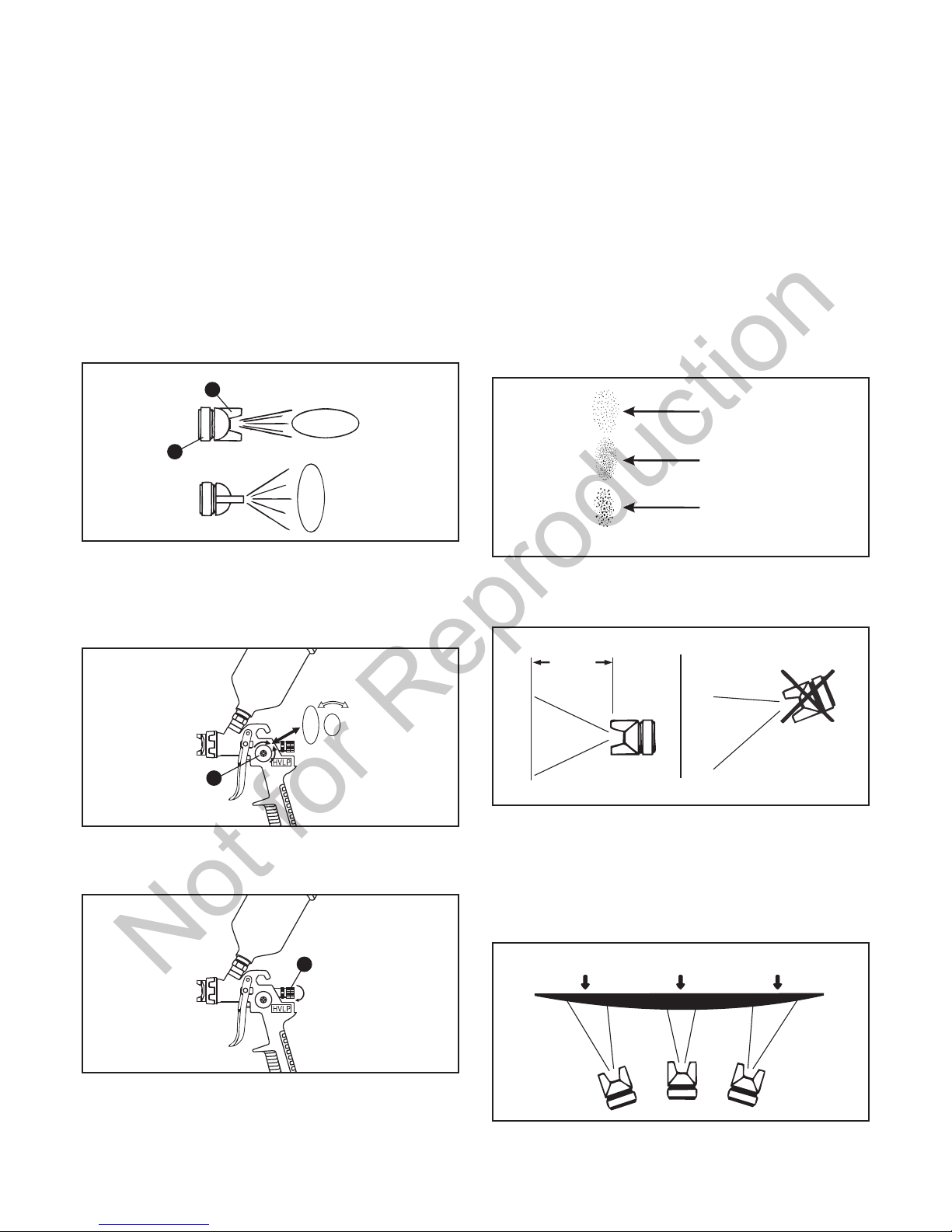
4. The pressure for atomization is controlled by the
regulator on the air source. The amount of fluid is
adjusted by the fluid control knob, the paint viscosity,
and the air pressure.
5. Failure to install appropriate water/oil removal
equipment could result in damage to the product or
workpiece.
1. Keep the work area clean and well lighted. Cluttered
benches and dark areas increase the risks of electric
shock, fire and injury to persons.
2. Keep bystanders, children and visitors away while
operating the tool. Do not use this product with other
people, children or pets in the work area.
3. Stay alert. Watch what you are doing and use
common sense when operating the tool. Do not use
the tool while tired or under influence of drugs,
alcohol, or medication.
4. Dress properly. Do not wear loose clothing or
jewelry. Keep long hair and gloves away from moving
parts.
5. Do not overreach. Keep proper footing and balance at
all times. Use a face mask/respirator and wear
ANSI-approved safety goggles when spraying. Always
spray in a well-ventilated area to prevent health and
fire hazards. Refer to Material Safety Data (MSDS) of
spray materials for details.
6. Never use oxygen, carbon dioxide, combustible gases
or any bottled gas as an air source for the tool. Use
only clean, dry, regulated compressed air at the rated
pressure or within the rated pressure ranges for best
spray gun performance and extend spray gun life.
7. Do not aim the spray gun at any dust or debris to
avoid any damage to workpiece.
General Safety Information
●Improper operation or maintenance of spray guns
could result in serious injury and/or property damage.
Read and understand all warnings and operation
instructions before using spray guns. When using
spray guns, basic safety precautions should always
be followed to reduce the risk of personal injury.
●Follow all local electrical and safety codes as well as
the United States National Electrical Codes (NEC) and
Occupational Safety and Health Act (OSHA).
The safety alert symbol is used to identify safety
information about hazards that can result in personal
injury.
A signal word DANGER, WARNING or CAUTION is used
with the alert symbol to indicate the likelihood and the
potential severity of injury.
DANGER Indicates a hazardous situation that, if not
avoided, will result in death or serious injury. This signal
word is to be limited to the most extreme situations.
WARNING Indicates a hazardous situation that, if not
avoided, could result in death or serious injury.
CAUTION Indicates a hazardous situation that, if not
avoided, could result in minor or moderate injury.
NOTICE Indicates information considered important, but
not hazard-related.
WARNING
WARNING Read manufacturer's instructions.
Not for Reproduction

6. To avoid cross-threading, all spray gun parts should
be screwed in hand tight initially. If the parts cannot
easily be turned by hand, be sure that you have the
correct parts, unscrew, realign, and try again. Never
use excessive force in matching parts.
7. Use only accessories identified by the manufacturer
for the specific tool model.
8. When servicing a tool, use only identical replacement
parts and/or authorized parts.
9. Use only lubricants supplied with the tool or specified
by the manufacturer.
10. Maintain spray guns with care. Keep spray guns clean
and oiled for best and safest performance.
11. Store the tool out of reach of children and other
untrained persons when it is idle.
Product Description
A
B
C
D
E
F
G
I
J
H
DESCRIPTION QUANTITY
PART
H.V.L.P Gravity Spray Gun
Paint Cup
Cup Lid
Air Cap
Air Cap Ring
Spray Pattern Adjustment Knob
Fluid Adjustment Knob
Air Adjustment Knob
Air Inlet
Trigger
Warning Label
1
1
2
1
1
1
1
1
1
1
1
A
B
C
D
E
F
G
H
I
J
K
Technical Specifications
SPECIFICATIONS
COMPONENT
Gravity
1.4 mm
600 ML
30-50 PSI
6.5 CFM
1/4 in. (6.35 mm) 18 NPS
1/4 in. (6.35 mm) (min. inner diameter)
Feed type
Fluid nozzle
Cup capacity
Operating pressure
Air consumption
Air inlet
Air hose
Assembly Instructions
Figure 1
Operation Instructions
A
B
Fluid filter
Fluid inlet
Figure 2
I
4 BRIGGSandSTRATTON.COM
NOTE The working pressure refers to the air line pressure
when the spray gun trigger (J) is pulled fully under
working conditions.
NOTE Apply the fluid filter to the fluid inlet of the spray
gun. (See Figure 1)
NOTE
●Before using desired paint in the spray gun, spray a
compatible thinner or solvent through the gun to remove
any contaminants and residues.
●Thin paints properly in accordance with the paint manufac-
turer's instructions before spraying. If necessary, carefully
strain the paint through a paint strainer or a piece of
cheesecloth.
●Fill the paint cup (B) about 3/4 full and start the air
compressor.
●Set up a piece of cardboard or other scrap material to use
as a target and adjust for best spray pattern.
1. Take out spray gun (A) and put on paint cup (B) with hand.
Make sure that the paint cup (B) is installed with spray gun
(A) tightly and correctly. (See Figure 1)
2. Connect air supply hose (not included) with the air inlet (I)
of spray gun (A). Use seal tape (not included) for airtight
connection. Do not overtighten. (See Figure 2)
3. Set the rated working pressure (i.e. 43 PSI) for best
performance. DO NOT exceed spray gun maximum
pressure of 50 PSI.
6388-00
Madein China/Hecho en China/Fabriqué en Chine
NERETIREZ PAS CETTE ÉTIQUETTE
AVERTISSEMENT
DONOT REMOVE THIS LABEL
WARNING
NOSAQUE ESTA ETIQUETA
ADVERTENCIA
PISTOLA DE PULVERIZACIÓN DE GRAVEDAD HVLP
H.V.L.P GRAVITY SPRAY GUN
PISTOLET À PEINTURE “GRAVITY” H.V.L.P
K
Not for Reproduction

Horizontal Fan
Vertical Fan
Figure 3
E
D
Figure 4
F
Figure 5
G
Paint too fine
Correct
Paint too coarse
Pattern Consistency (Atomization) Figure 6
6-12 in.
Figure 7
5
NOTE The fluid adjustment knob (G) can be adjusted
either clockwise or counterclockwise to finely adjust
pattern consistency. Before spraying on workpiece,
practice a few minutes on a cardboard target to ensure that
the pattern size and consistency are set correctly.
NOTE During normal use, the air cap (D) is adjusted to be
horizontal. This provides a vertical fan-shaped pattern
which gives maximum and even material coverage as the
gun is moved back and forth parallel to the surface being
finished.
NOTE Always keep spray gun (A) moving parallel to the
surface being covered while spraying. Stopping gun move-
ment in mid-stroke will cause a build-up of paint and will
result in runs. Do not fan the gun from side to side while
painting. This will cause a build-up of paint in the center of
stroke and an insufficient coating at each end. (See Figure 8)
●Test the consistency of the paint by making a few strokes
on a cardboard target. If paint still appears too thick, add a
small amount of thinner. Do not exceed paint manufac-
turer's thinning recommendations.
1. Adjust the direction of air cap (D) to be either horizontal or
vertical as required by loosening air cap ring (E) 90
degrees with hand. Hand tighten the air cap ring (E) after
adjustment. (See Figure 3)
2. Set pattern size for desired shape. For full pattern, open
spray pattern adjustment knob (F) counterclockwise. For a
round pattern, turn spray pattern adjustment knob (F)
clockwise. (See Figure 4)
3. Turn the fluid adjustment knob (G) fully clockwise until
closed. (See Figure 5)
4. Holding the gun 6-12 in. away from workpiece depending
on material and atomizing pressure, spray a short burst
while turning the fluid adjustment knob (G) until desired
pattern/atomization is obtained. If the spray is too fine,
which is caused by too much air from amount of paint
being sprayed, reduce the air pressure or open the fluid
adjustment knob (G) more to spray more paint. If the spray
is too coarse/spitting blobs, reduce the amount of paint
with the fluid adjustment knob (G) or thin the paint more.
(See Figure 6)
5. Keep spray gun (A) at the right angle of 90 degrees to the
surface being covered while spraying. (See Figure 7)
Thin coat Heavy coat Thin coat
INCORRECT
Figure 8
Not for Reproduction

DAILY CLEAN-UP
NOTE
●Local codes may require specific cleaning methods and
equipments. Follow local codes and manufacturer's
recommendations for the use of disposal of spray paints
and solvent.
●Clean the spray gun IMMEDIATELY after use. Paint and
other materials dry quickly in the small passages inside
the spray gun.
1. Remove and empty paint cup. Rinse with a solvent
recommended for the paint.
3. Remove and check the fluid needle for excessive wear at
the tip and straightness.
NOTE If the fluid needle tip is worn more on one side than
the other, either the needle is bent or the gun body has been
dropped or knocked out-of-line. There are no adjustments
that can be made to a bent gun body. Test the needle by
rolling on a flat surface. Replace if necessary.
4. Check and replace any damaged gaskets and/or packing
nuts.
5. Unscrew the needle packing seat and replace the needle
packing only if a leak will not stop when the needle
packing seat is tightened. DO NOT overtighten the needle
packing seat because this will restrict movement of the
fluid needle.
6. Reassemble in verse order of the above and use a
non-silicone oil on the moving parts. Apply Vaseline or
light grease on all threaded connections.
2. Refill the paint cup with clean solvent and attach the cup
to the gun body. Spray solvent through the gun into a
container while shaking the spray gun. Once the paint cup
is empty, repeat the process until the solvent comes out
clean. Wipe the gun exterior with a solvent-soaked rag.
3. Disconnect the spray gun from air supply. After discon-
necting, point the spray gun into the spent solvent
container and squeeze the trigger again to make sure that
no air remains.
4. Remove the air nozzle and soak in solvent until clean. Use
a small brush for stubborn stains if necessary. Toothpicks
or small brushes may be used to clean air passages.
6. After using water to clean out the spray gun, spray mineral
spirits through the gun to prevent corrosion.
7. Clean and flush gun thoroughly to neutralize any contami-
nants corrosive to the spray gun.
8. Use a non-silicone oil or a light lubricant on all moving
parts when reassembling. Use Vaseline or light grease on
all threaded connections before storage.
PERIODIC CLEAN-UP
NOTE Due to improper cleaning and/or paint, it may be
necessary to inspect and clean the internal parts and the gun
body.
1. Examine the openings of the air nozzle tip and fluid nozzle
tip. If clogged, remove and soak them in solvent.
2. A brush, toothpick or something similar may be used to
dislodge the dried paint from holes and passages.
5. Clean gaskets with a solvent-soaked rag.
WARNING Never use metal objects to clean
precisely drilled passages. Damaged passages will
cause improper spraying.
WARNING Never use metal objects to clean
precisely drilled passages. Damaged passages will
cause improper spraying.
WARNING Never immerse gaskets or spray gun
body in solvents to prevent damage.
Care and Maintenance
6 BRIGGSandSTRATTON.COM
6-12 in.
Pull
Trigger
Start Stroke
Release
Trigger
End Stroke
Figure 9
Figure 10
NOTE The amount of paint being applied can be varied by
the speed of stroke, distance from the workpiece and
adjustment of the fluid adjustment knob (G). If speed of
stroke is too slow, paint will be wet on workpiece and may
run. If speed of stroke is too fast, paint will be dry and
uneven on workpiece.
6. Trigger the gun properly. Start the gun moving at the
beginning of the stroke before squeezing the trigger (J)
and release the trigger (J) before stopping gun movement
at the end of stroke. This procedure will feather/blend each
stroke with the next without showing overlap or uneven-
ness. (See Figure 9)
NOTE Two thin coats of paint will yield better spraying
results and have less chance of runs than one heavy layer.
7. Overlap strokes just enough to obtain an even and fine
coat. (See Figure 10)
8. Use a piece of cardboard as a shield to catch overspray at
the edges of workpiece and protect other surfaces. Use
masking tape (not included) to cover other areas if needed.
Not for Reproduction

Troubleshooting
PROBLEM SOLUTIONPOSSIBLE CAUSE
Soak nozzle in solvent to loosen clog, then blow
air through until clean. To clean nozzle tip use a
broom straw or toothpick. Never try to detach
dried material with sharp tool.
a) Trigger air nozzle.
b) Take off air nozzle and wipe off nozzle tip,
using a rag moistened with thinner.
a) Reduce air pressure.
b) Increase material control by turning fluid
adjustment knob counterclockwise.
a) Release needle packing seat, put a few drops
of machine oil on the needle packing,
retighten.
b) Take off fluid nozzle, clean rear of nozzle and
seat in gun body. Replace nozzle and bring
in tight to body.
a) Re-adjust gun. Follow instructions carefully.
b) Clean.
c) Clean.
d) Lubricate.
a) Check air supply and air lines.
b) Increase air pressure.
c) Open fluid adjustment knob more.
d) Thin material properly.
a) Tighten, but not so tight as to grip needle.
b) Replace packing or lubricate.
a) Tighten, but not so tight as to grip needle.
b) Replace packing or lubricate.
Move gun further from surface.
One side of nozzle is clogged.
a) Loose air nozzle.
b) Material around outside of air
nozzle has dried.
a) Atomization air pressure is set too
high.
b) Trying to spray a thin material in
too wide a pattern.
a) Needle packing around needle is
dried out.
b) Fluid nozzle loosely installed, or
dirt between nozzle and body.
a) Gun improperly adjusted.
b) Dirty air nozzle and lock ring.
c) Fluid tip obstructed.
d) Sluggish fluid needle.
a) No air pressure at gun.
b) Air pressure too low.
c) Fluid adjustment knob not open
enough.
d) Fluid too heavy.
a) Needle packing seat loose.
b) Needle packing worn or dry.
a) Gun held too far from surface.
b) Atomization pressure set too high.
Gun held too close to surface.
Right or left heavy
spray pattern
Top or bottom heavy
spray pattern
Split spray pattern
Intermittent spray
Improper spraypattern.
Will not spray.
Fluid leakage from needle
packing seat.
Thin, sandy coarse finish.
Thick, dimpled finish
resembling orange peel.
STORING
1. When not using the spray gun, turn the fluid adjustment knob counterclockwise to open fully. This will reduce the spring
tension on the fluid needle tip.
2. The spray gun must be well cleaned and lightly lubricated.
3. Store the spray gun in a dry and safe place out of reach of children.
7
Not for Reproduction

Exploded Diagram and Parts List
Part No.
Description Qty.
Part No.
Description Qty.
1
2
3
4
5
6
7
8
9
10
11
12
13
14
15
16
17
18
19
20
21
22
23
Gun body
O-ring
Needle packing screw
Air ring
Gasket
Nozzle seat
Fluid nozzle
E-clip
Air cap
Bushing
Lock ring
Spring
Valve stem
Gasket
Valve
Needle packing screw
Air regulating stem
Gasket
Spring
O-ring
Air adjustment seat
Air adjustment knob
Air inlet
1
1
1
1
1
2
1
1
1
1
1
1
1
1
1
1
1
3
1
1
1
1
1
24
25
26
27
28
29
30
31
32
33
34
35
36
37
38
39
40
41
42
43
44
45
46
E-clip
O-ring
Pattern regulating seat
O-ring
Pattern regulating valve
Patern adjustment knob
Screw
E-clip
Trigger
Bolt
Bolt
Fluid needle
Spring
Fluid adjustment seat
Fluid adjustment knob
Fluid inlet nipple
Fluid filter
Paint cup
Needle packing
Needle seat
Needle packing
Wrench
Cleaning brush
1
1
1
1
1
1
1
2
1
1
1
1
1
1
1
1
1
1
2
1
3
1
1
8 BRIGGSandSTRATTON.COM
45
41
11
10
9
8
7
16
44
15 14
13
23
17
18
19
12
18
20
21
22
6
5
4
3
2
42
40
A
39 35
43
36
31
31
24 25
26
27
28
29
30
34
32
33
37
38
1
46
Not for Reproduction

Briggs & Stratton™ Air Tool Warranty Policy
LIMITED WARRANTY
These are our standard warranty terms, but occasionally there may be additional warranty coverage that was not determined at
time of publication. For a listing of current warranty terms for your air tool, go to BRIGGSandSTRATTON.COM
This Limited warranty does not include the following:
A. Parts that are worn or broken or which have become inoperative due to abuse, misuse, accidental damage, neglect or lack of
proper installation, operation or maintenance (as outlined in the applicable owner’s manual or operating instructions) or product
that has been used for industrial, professional, commercial or rental purposes;
B. Normal wear and tear or expendable parts or accessories that may be supplied with the product which are expected to become
inoperative or unusable after a reasonable period of use;
C. Routine maintenance and consumable items such as, but not limited to fuel, lubricants, valves, belts, knobs, nuts, uids,
tune-ups, or adjustments;
D. Damage caused by repairs made or attempted by persons not authorized by the manufacturer;
E. Product that was sold to the original purchaser as reconditioned or refurbished product (unless otherwise specied in writing);
F. Product or parts thereof if any part from another manufacturer has been installed or any repairs or alterations have been made
or attempted by unauthorized persons;
G. Normal deterioration of the exterior nish such as, but not limited to, scratches, dents, paint chips, nor any corrosion or
discoloring by heat, abrasive and chemical cleaners;
H. Component parts sold by and identied as the product of another company, which shall be covered under the other product
manufacturer's warranty, if any.
For questions about our warranty on this product, contact us at:
Alton Industry LTD. Group
1031 North Raddant Road
Batavia Illinois 60510
888-899-0146
www.altonindustries.com
January, 2016
Briggs & Stratton™ is a trademark of BRIGGS & STRATTON CORPORATION and is used under license to Alton Industry
Co. Ltd® Alton Industry Co. Ltd warrants this Briggs & Stratton brand product for a period of one year from the date of
original retail purchase against defects in materials and workmanship. Subject to the conditions and limitations described
below, if Alton Industry Co. Ltd determines this product is covered under this warranty, it will be replaced with the same
model or one of equal value or specication, at Alton Industry Co. Ltd's option. Alton Industry Co. Ltd will bear the cost of
replacement. The purchaser must contact Alton Industry Co. Ltd® for all warranty authorizations.
There is no other express warranty. Implied warranties, including those of merchantability and fitness for a particular
purpose, are limited to one year, or to the extent permitted by law. Liability for incidental or consequential damages are
excluded to the extent exclusion is permitted by law. Some states or countries do not allow limitations on how long an
implied warrant lasts, and some states of countries do not allow the exclusion or limitation of incidental or consequential
damages, so the above limitation and exclusion may not apply to you. This warranty gives you specic legal rights and you
may also have other rights which vary from state to state or country to country.
Save your proof of purchase receipt. If you do not provide proof of the initial purchase date at the time warranty service is
requested, the manufacturing date of the product will be used to determine the warranty period. Product registration is not
required to obtain warranty service on Briggs & Stratton products.
Not for Reproduction
Table of contents
Other Briggs & Stratton Paint Sprayer manuals