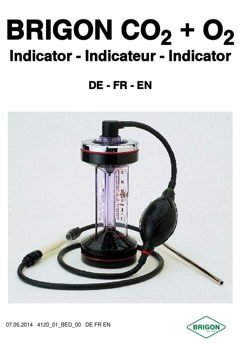
Brigon 500 NT User manual

Operating instructions
Operating instructionsOperating instructions
Operating instructions
BRIGON 500 NT
BRIGON 500 NTBRIGON 500 NT
BRIGON 500 NT
Professional hand-held analyser for the
direct measurement of CO
2
Measure exactly,
what you need!
Part 3 for CO
21.04.2010 Doc. no. 16334 Rev. 0 INT
measurement
instruments for
professionals

Page 2 BRIGON 500 NT
Contents:
Product description 3
View of the plug connections 3
Commissioning, handling, storage 4
Important Safety Instructions 4
Definitions and instructions 5
Rotary switch 5
Common symbols and abbreviations 5
Recommendations for measuring 6
Operation 7
Rotary switch position Menu 9
Menu Setup 9
Menu Pressure (tightness test) 9
Menu Report 9
Menu SCREEN 10
Menu SERVICE 10
Rotary switch position Status 10
Rotary switch position AUX 10
Rotary switch position O
2
/Eff (stack loss/efficiency) 11
Rotary switch position CO/CO
2
11
Rotary switch position p (Pressure/Differential pressure) 11
Rotary switch position ±∆p (Tightness test) 11
Rotary switch position ∆T (differential temperature) 12
Rotary switch position ext.CO (CO in ambient air) 12
Additional function MANOMETER 12
Calibration 13
Stack loss measurement / Mid-stream search 13
Pressure/Draught, Differential pressure measurement 14
Maintenance and Service 14
Battery, power supply 14
Water trap and particle filter 15
CO
2
- and CO sensor 15
What to do, if... 15
Technical data 18
NOTES 19
Disposal 20

BRIGON 500 NT Page 3
Product description
BRIGON 500 NT measures CO
2
, CO, differential pressure as well as flue gas and ambient air
temperature. The instrument calculates O
2
, CO
undiluted
, lambda, stack loss q
A
and efficiency
(Eta).
The data are displayed in function oriented measuring windows or user selectable window in a
back-lighted display.
When storing a reading, as for example Oxygen concentration O
2
, the readings of flue gas
temperature and ambient air temperature as well as the calculated values q
A
, differential
temperature, Eta and CO
2
are stored and can be optionally printed.
Sensor calibration takes max. 90 seconds and is performed automatically after switching on
the analyser.
Flue gas analyser has an integral watertrap with particle filter. Damp from the flue gas is
condensed and collected in the watertrap. The filter prevents smut particles from getting into
the analyser.
Please, note that your flue gas analyser is a product designed, manufactured and sold solely
for the purpose of flue gas analysis of burners. So, please, use your analyser and its
accessories only for this purpose.
Should you require to use it for other purposes, please obtain our written permission to do so
first.
Keep these operating instructions in a safe place close to your analyser as quick
reference should the need arise.
View of the plug connections
Probe ambient
air temperature
Probe flue gas
temperature
Gas
connection
Condensate outflow
with rubber plug
Charger
socket
Differential pressure
connection P1 + P2

Page 4 BRIGON 500 NT
Commissioning, handling, storage
Your BRIGON 500 NT is delivered with 4 mignon batteries. Even in switched off mode the
batteries supply the clock of the analyser so, that the batteries are discharging even if you do
not use your BRIGON 500 NT.
Therefore we recommend to remove the batteries from your analyser if you do not need it for a
few days.
To prevent an impairment of the electrochemical sensors, please avoid the use and storage of
your BRIGON 500 NT in the environment of perspirating substances, e.g. solvents. Do not use
these substances for cleaning your BRIGON 500 NT either.
Take care that no moisture or condensate gets into the analyser.
Always make sure the batteries resp. rechargeable batteries (option) are fully
charged, especially if the analyser has not been used for a long period of time.
Important Safety Instructions
Your BRIGON 500 NT has been developed and manufactured with the utmost care to ensure
safe and reliable operation over many years. As with all electronic appliances, you must be
aware of certain general precautions. These are intended for your safety and to protect the
analyser from damage.
Read these operating instructions carefully, and keep all documents in a safe place for future
reference.
Be sure that...
• you carry out only the routine maintenance according to the operating instructions.
Opening the case of the instrument can cause damage to vital parts. The warranty will
become void if repair/modifications are undertaken by unauthorised persons!
• after having changed parts of the BRIGON 500 NT which have an influence on the
accuracy of the measurement, the concerned measuring channel should be tested at the
authorised service point for the reason of quality management.
• Magnetic fields – emerging from the magnets of the soft case of the analyser – can set
off sparks, can have an influence on pacemakers, can disturb electronic and
electrotechnical components and can delete data memories.
Take care that...
• your power outlet data matches that of the charger. If in doubt, consult your dealer or
BRIGON MESSTECHNIK directly.
• Do not expose your BRIGON 500 NT to temperatures higher than 50°C (as they can for
example occur in a car being parked in the blazing sun). It could happen that the analyser
will get overheated and that especially the electrochemical sensors will be destroyed. Do
also avoid temperatures below -20°C.

BRIGON 500 NT Page 5
• the charger is disconnected from the power outlet before cleaning the analyser. Use only
a damp cloth.
Do not use cleaning agents containing solvents!
Definitions and instructions
Rotary switch
Common symbols and abbreviations
T1 Flue gas temperature in °C
T2 Ambient air temperature in °C
∆T Differential temperature °C
O
2
Oxygen in Vol%
CO
2
Carbon dioxide in Vol%
CO/CO
2
Ratio carbon monoxide to carbon dioxide
Stack loss
q
A
Menu: Settings (Setup)
Aux Aux(iliary): user selectable window
ηN Combustion efficiency Eta (Nett; factory setting)
ηG Combustion efficiency Eta (Gross)
ηC Combustion efficiency Eta (Condensing)

Page 6 BRIGON 500 NT
P Pressure/draught
λExcess air (Lambda)
CO Carbon monoxide
COp Carbon monoxide in ppm
COu Carbon monoxide undiluted in ppm
N<-C->G Various stack loss calculation types (nett, gross and condensing). Factory setting
N
FUEL Fuel type
LOG Memory cell
-OC- Temperature probe is not connected
-O>- Reading or calculated value is too small, too high or can not be calculated
---- O
2
/CO/NO sensor calibration is not successful
Recommendations for measuring
Take measurements during normal operation of the burner. To avoid incorrect combustion
conditions during start-up, take measurements only after the burner has reached its particular
operating temperature (e.g. Boiler Water Temperature at least 60°C).
Before storing the readings, the sensors should be supplied with flue gas for at least 3
minutes.
The sampling point in the flue should be at least 2D (twice the diameter) downstream of any
bend. A sampling point at a different location is only allowed if it is not practically possible to
place the aperture 2D away from the joint (e.g. if there is a bend there) and the flue gas
conditions are stable and reproducible.
Before each measurement
Check the tightness of your probe unit (probe, O-rings, grip, filter, tubing and gas plug) from
the top of the probe to the end of the tubing with an appropriate testing device e.g. BRIGON-
tightness-tester for probes and tubes, Item.-No.: 3039.
The cables must be clean inside, i.e. no dirt or condensate, and it must not be pinched while
measuring.
Have your BRIGON 500 NT checked regularly by an authorised service point or directly by
BRIGON MESSTECHNIK. The CO
2
-sensor and the CO-sensor must be checked every year.
Take care that the gas outlet at the bottom of the analyser is always open.

BRIGON 500 NT Page 7
Operation
Switching
on By pressing the button you switch the analyser on. The sensors are
calibrated automatically. Make sure that the probe is not inserted into the flue gas
pipe and hold your analyser in fresh air.
On switch on, the analyser beeps 4 times and displays date, time and model
number. The countdown runs from 90 to 0 untill sensors are ready to use.
Through integral dynamic calibration the countdown might be finished within 20 -
30 seconds. Calibration will last longer as the analyser gets older or in case it
was overstressed with high CO concentration. If the repeated calibration was not
succesfull, sensors must be tested and, if necessary, replaced.
Note During calibration both temperature probes should be connected to the
device!
If the ambient air probe (T
2
) is connected to the analyser during the countdown,
this temperature probe is used for further measurements. In case any probe (for
example, flue gas probe) is connected to the analyser during countdown, the
temperature, measured by the flue gas probe will be used for further
measurements and calculations as T
2
. If no probe is connected, the analyser’s
internal ambient temperature sensor will be used untill the analyser is switched on
the next time.
Selecting
fuel type
Turn the rotary switch to the position MENU, press the buton twice, select
the required fuel type using the buttons , press confirm button and
turn the rotary switch to the required measuring program position.
Switching
off
By pressing the button you can switch your analyser off. The displays
counts down from 30 with the pump on to clean the sensors with fresh air. Make
sure that probe connected to the analyser is in fresh air.
Press the button to stop the countdown and return to the measuring mode.
Attention: BRIGON 500 NT will switched off only when the CO reading is below 20
ppm. If the CO reading is higher, the analyser displays CO HIGH and flush the
sensor further.
Navigation
Use the buttons to change the settings, to navigate in MENU, to
switch between the measuring windows, to zero the pressure sensor and to
choose the display order.
Take care that the buttons must be pressed shortly or longer to perform certain
functions in different measuring programs.

Page 8 BRIGON 500 NT
Print To print out the readings from the current display or from the memory cell press
the button shortly and quickly release it. The analyser displays „Printing“
until this is complete. Press and release the key again to abort printing.
Back
lighting Press the button shortly. Backlighting of the display and pocket light turns
ON or OFF.
Be aware, that using the lights increases the power consumption of the batteries
and leads to a shorter opereating time.
Pump
The analyser normally operates with the pump on in any measuring mode. Press
the button shortly to switch the pump OFF or ON again.
When the pump is switched off, the analyser displays -PO- (Pump off) in the
corresponding display line and a double beep sound comes regularly.
Attention: the pump will not switch OFF if CO-reading is above 20 ppm. It
helps to protect the CO sensor from damage.
Zero
pressure
sensor
Press and hold the button. The top line of the display shows „CAL ZERO“.
Storing
the
readings
To store the reading, press and hold the button until the top line display
shows „LOG NO“.
The instructions on viewing and printing the stored readings you can find in
chapter MENU/Report (see next page).
Memory
capacity
Your BRIGON 500 NT can store different readings:
Stack loss readings: 99 memory cells
Tightness test: 20 memory cells
Differential temperature readings: 20 memory cells
CO readings in ambient air: 20 memory cells
At the end of the measurement the next available memory cell is taken
automatically, for example LOG 02, to store the readings.
To view the stored data press the buttons in the measuring mode untill
the analyser shows „DISPLAY“ and confirm it with the button. You can
choose storage cells by pressing the buttons and confirming your
choice with the button.

BRIGON 500 NT Page 9
Rotary switch position Menu
SETUP
PRESSURE
REPORT
DISPLAY
SERVICE
To use your analyser effectively there are various measuring programs at
your disposal. Pressing the buttons you can switch between the
menu functions and confirm with the button.
Menu Setup
SET FUEL
EXIT
LANGUAGE
SET DATE
SET TIME
N<-C-G
In SET FUEL you can choose fuel type.
Pressing EXIT you finish SETUP function.
In LANGUAGE you can choose different country settings.
In SET DATE you can set date.
In SET TIME you can set time.
In N<-C->G setting you can switch between various stack loss or
combustion efficiency calculation modes. Standard in Germany is N (nett).
Menu Pressure (tightness test)
SMOOTH
EXIT
TIME
PS.UNITS
RESOLVE
SMOOTH ON or OFF:
Pressing EXIT you finish this function.
TIME: Pressure sensor stabilisation time TIME 01 and TIME 02
in minutes.
PS.UNITS: hPa, mmHg, PSI, kPa, Pa, mmH
2
O, mbar, inH
2
O
RESOLVE: Resolution HIGH or LOW: Resolution of readings
Menu Report
COMB´N
EXIT
ROOM CO
TEMP
TIGHTN´S
PRESSURE
You can choose the required report:
COMB´N = Combustion test
ROOM CO = CO in ambient air
TIGHTN´S = Tightness test
TEMP = Differential temperature test
PRESSURE = Pressure test
DISPLAY shows you the stored readings. The analyser displays cell
number in the top line e.g. LOG 01.

Page 10 BRIGON 500 NT
Pressing the button quickly you can change the content of the second
line on the display, pressing the button quickly you can change the
content of the third line on the display. Pressing the arrow buttons longer
you can switch between the storing cells (e.g. from LOG 01 to LOG 02).
To print out the readings press the button.
Pressing EXIT you finish this function.
Menu SCREEN
CONTRAST
EXIT
HEADER
EXIT
CONTRAST: You can set screen contrast between 00-20, factory setting 04
Pressing EXIT you finish this function.
HEADER: You can set the printer text, 2 lines with 20 signes each
AUX: You can select the readings to be displayed in each line (1 - 4).
Menu SERVICE
CODE
0000
Functions for Authorized Service Points.
Rotary switch position Status
BAT 70
12:00:00
01/04/08
CAL 375
To display batteries/rechargeable batteries capacity, time, date and
calibration status (for internal purposes of Service points)
Rotary switch position AUX
(Example)
λ
1.21
P 90.00
4.5
T
1
122.8c
User selectable window

BRIGON 500 NT Page 11
Rotary switch position O
2
/Eff (stack loss/efficiency)
O
2
%
4.4
T
1
122.8c
T
2
21.6c
EfN 95.1
1. line: O
2
concentration in %
2. line: flue gas temperature in °C
3. line: ambient air temperature in °C
4. line: alternative stack loss or efficiency in %
Consult the chapter „Stack loss measurement/ Mid-stream search“
Rotary switch position CO/CO
2
LIGHT OIL
CO
2
%
12.2
COp 100
COu 127
1. line: current fuel type
2. line: CO
2
reading in %
3. line: CO reading in ppm
4. line: CO
undiluted
reading in ppm
Rotary switch position p (Pressure/Differential pressure)
PRESSURE
PRESS TO
ZERO
↓
Press the button to zero pressure
sensor. Do not change the position of
BRIGON 500 NT until the end of the
measurement!
PRESSURE
P 12.5
mbar
12:00:00
Rotary switch position ±∆p (Tightness test)
PRESSURE
PRESS TO
ZERO
↓
Press the button to zero pressure
sensor. Do not change the position of
BRIGON 500 NT until the end of the
measurement!
STABIL’N
P1 0.00
mbar
START ↓
TIGHTN´S
P1 90.00
mbar
START ↓
Connect the pressure plug P1 to the sampling point and press the
button. The measurement is taken during the pre-defined TIME 01
(standard 60 sec., see Menu PRESSURE) and the reading Pressure P1 is
stored temporarily.

Page 12 BRIGON 500 NT
TIGHTN´S
P1 90.00
P2 91.00
TIME 120
Press the button again. The new measurement is taken during the
pre-defined TIME 02 (standard 120 sec., see Menu PRESSURE) and the
reading Pressure P2 is stored temporarily.
LOG 03
P1 90.00
P2 91.00
PRINT ↓
Once the measurement is taken, the analyser displays the storage cell for
the readings P1 und P2 (e.g. LOG 03). To print our the readings press the
button.
To exit this function turn the rotary switch to any other position.
Rotary switch position ∆T (differential temperature)
TEMP
T1 25.4c
T2 10.2c
∆T 15.2c
To print our the readings press the button
Rotary switch position ext.CO (CO in ambient air)
ROOM CO
TO START
PRESS
↓
To start the Room CO test press the
button. The analyser records 15
sets of 1 minute samples.
TEST = Current measurement number
LOG = storage cell number
ROOM CO
CO 00
TEST 00
LOG 01
Additional function MANOMETER
On switch on press and hold the button, the analyser switches to the MANOMETER
mode. Alle the other functions except for SETUP are not available. To use these functions
switch OFF and again ON your BRIGON 500 NT.
B500NT
12:00:00
01/04/08
TIME 20
Pressure sensor is stabilized within
max. 20 sec.
To zero pressure sensor press the
button. Do not change the position of
the analyser untill the end of the
measurement!
P 15.40
T1 25.4c
T2 10.2c
∆T 15.2c

BRIGON 500 NT Page 13
Calibration
During sensor calibration sensors are supplied with fresh air for approx. 90
seconds
Purge the sensor with fresh air before taking measurements in every new location.
Connect both temperature probes to the analyser during the countdown.
Should one of the readings be not correct after the calibration, the analyser
displays the error.
Purge the sensors with fresh air for at least 15 minutes with the pump ON.
Should the analyser display the error repeatedly, the respective sensor should be
replaced.
If CO-sensor was overstressed with more than 2000 ppm, purge the sensor with
fresh air.
Stack loss measurement / Mid-stream search
Stack loss measurements must be taken from the mid-stream (area with the
highest flue gas temperature).
Preparations:
Before each measurement check the tightness of your probe unit (probe, O-rings,
grip, filter, tubing and gas plug) from the top of the probe to the end of the cable
with an appropriate testing device e.g. BRIGON-tightness-tester for probes and
tubes, Item.-No.: 3039.
Check the plug’s orientation is being correct.
Mid-
stream
search :
Seek the point with the highest flue gas temperature monitoring the displayed T1 –
reading.
Fixing
the
probe :
Once the probe is in mid stream (point with the highest flue gas temperature), use
the cone to fix it in the sampling point.

Page 14 BRIGON 500 NT
Pressure/Draught, Differential pressure measurement
You can measure pressure/draught with
standard probe as well as with the probe
for measuring chimney draught (option).
Connect the cable plug to the pressure
slot P1.
If you want to measure differential
pressure, connect the cable plugs to the
slots P1 and P2, where P1 is “+“ and P2
is “- “ .
Pressure slot P1 + P2
To achieve the highest accuracy, do not move the analyser until the
measuring test has been completed!
Maintenance and Service
Your BRIGON 500 NT is almost entirely maintenance-free. You can easily take a
few maintenance operations and replace some wearing parts not to waste valuable
working time for service/repairs.
After having replaced the parts which influence the accuracy of the measurement,
the concerned measuring channel should be tested by the authorised service point
for the reason of quality management.
Lubricate cable couplings and o-ring of the water trap thriftily with oil when
necessary.
Be sure,
- that lubricant oil doesn´t get into the plugs !
- that when you have finished measurements no condensate remains in the
probe and connecting cable.
Battery, power supply
Your BRIGON 500 NT is delivered with 4 mignon batteries. Even in switched off mode the
batteries supply the clock of the analyser and are discharging even if you do not use your
BRIGON 500 NT.
You can also operate your analyser with mains adapter or other standard batteries.
Please, be aware that battery capacity displays remaining capacity in percentage, e.g.
new batteries: 6 V = 100. Fully recharged batteries: 4,8 V = 80.

BRIGON 500 NT Page 15
Water trap and particle filter
To protect the sensors from condensate and dirt particles in flue gas, it is extremely important
to use the combined water trap and particle filter.
The condensate from the flue gas is trapped in a cell. Due to transparent material you are
able to control the condensate level and thus empty the cell through the rubber stopper if
necessary.
The particle filter is used to retain smallest soot- and dirt particles. Check the filter regularly
and replace if necessary. The particle filter may become wet during long time measurements.
If so pull the filter out of the cell. When you replace it, take care that the o-ring is not damaged.
After a measurement with high condensate volume we advise to open the water trap and dry it
together with the cable by room temperature.
CO
2
- and CO sensor
Used up: If the analyser displays „-----"or „error“ after several calibrations were
performed, the corresponding sensor must be replaced.
Tip: CO
2
and CO sensor can only be replaced by BRIGON
MESSTECHNIK or the authorized service point, as the analyser has to
be recalibrated with testing gases.
To ensure excellent performance we recommend to use only BRIGON original accessories
and spare parts. BRIGON MESSTECHNIK takes no responsibility for any damage resulting
from usage of other accessories and spare parts, which could have been prevented by using
BRIGON original spares.
Service and maintenance which exceeds the routine procedures described in this manual, may
only be performed by BRIGON MESSTECHNIK directly or by the authorised service point.
BRIGON MESSTECHNIK accepts no claims for damage resulting from repair or modifications
performed by an unauthorised person.
What to do, if...
You will soon discover that your analyser is exceptionally intelligent. It does not accept
"impossible" readings, prevents measurement errors and uses optical or acustic warnings to
draw your attention to error sources. The analyser makes it easy for you to deal with any
problems yourself in (almost) every situation.
Switching-on
not possible:
The analyser cannot be switched on resp. switches off automatically although
the power supply is sufficient: check if the batteries are placed correctly in the
sockets and contact the built-in springs.

Page 16 BRIGON 500 NT
Sensors
----
If the analyser displays „-----" as CO
2
or CO reading, purge the sensors for at
least 15 minutes with fresh air. If the analyser still displays „-----" after repeated
calibration, the corresponding sensor must be replaced.
If CO-sensor has been overstressed with more than 2000 ppm, purge the
sensor with fresh air.
The analyser can also display „-----" if the batteries capacity is low. Replace the
batteries or operate your analyser via the adapter.
-OC-
-O>-
The analyser displays „-OC-„ or „-0>-„ if the reading exceeds or is below the
acceptable range.
The same applies if the temperature probe is not connected, a sensor has not
been successfully calibrated or a calculated value is not within acceptable
range.
Check that the temperature probe is connected correctly.
O
2
, CO or
pressure
readings are
not correct
or „zero“
Check the probe from the end of the probe up to the analyser plug-in for leaks.
Take care that the o-ring on the water trap filter is placed correctly and is not
damaged.
Check if the particle filter is wet, its orientation is correct as well as if o-ring and
the rubber stopper are positioned properly.
Check if the gas plug is connected to the analyser’s correct socket.
No printout: If the thermoprinter prints, but the paper is blank, check if the paper has been
put into the printer the wrong way round. Remove the roll and turn it over.
Also check printer‘s batteries.
No
response:
Analyser does not respond and can not be switched off: perform a „Reset" by
switching off the power supply, i. e. removing the batteries resp. rechargeable
batteries and/or the charger shortly (2 min) and then reconnecting them. Please
check time and date afterwards and correct them if necessary.
Service: Always return your analyser for service or repairs together with all connecting
cables, probes, factory control report , detailed description of the problem and
the invoice to your supplier.

BRIGON 500 NT Page 17
Warranty: All BRIGON Messtechnik GmbH instruments, probes and accessories are
guaranteed against manufacturing defects or component failure for a period of
12 months, providing they are used under normal conditions for the purpose for
which they are designed. This guarantee does not cover normal wear and tear,
comsumables, damage due to misuse, abuse or incorrect maintenance. This
guarantee offers a free of charge repair or replacement at the Company's
discretion, provided the product is returned for inspection. The Company shall
be under no liability whatsoever for any defect in the goods.
The warranty will become void if repair/modifications are
undertaken by unauthorized persons!
You can find BRIGON service points at: www.brigon.de or contact us -
we advise you the shortest way:
Tel. +49 61 06 / 82 07-13

BRIGON 500 NT Page 18
Technical data
Flue gas temperature
Range: -0°C .. + 600°C Type K, 0..400 °C
TÜV approved acc. to EN 500379-1 and -2
Resolution: 0,1 °C
Accuracy: ≤±2 °C (up to 125 °C)
≤±3 °C (125...250 °C)
≤±4 °C (from 250 °C)
t0,98-time ≤50s
Ambient air temperature
Range: -0°C ... + 100°C Type K, 0...80°C
TÜV approved acc. to EN 500379-1 and -2
Resolution: 0,1 °C
Accuracy: ≤±1 °C, t
0,98
-time ≤120s
CO
2
concentration
Range: 0...20,0 Vol% CO
2
TÜV approved acc. to EN 500379-1 and -2
Resolution: 0,1 Vol%
Accuracy: ≤±0,2 Vol%, t
0,97
-time ≤50s
CO concentration
Range: 0...2000 ppm
TÜV approved acc. to EN 500379-1 and -3
short-time overstressing up to 4000 ppm possible
Resolution: 1 ppm
Accuracy: ≤±20 ppm (up to 400 ppm)
≤±5 % from reading (over 400 ppm)
Pressure and Draught
Range: -80 mbar ... + 80 mbar
TÜV approved acc. to EN 500379-1 and -2
Resolution: 0,01 mbar
Accuracy: ≤±0,02 mbar (up to ±5 mbar)
≤±1 % from reading (over ±5 mbar)
Additional Specifications
Ambient operating
range:
+ 5 ... + 40 °C
Transport and
storage temperature:
- 20 ... + 50 °C
Approval: TÜV By RgG 267 for O
2
, T
flue gas
and T
ambient air

BRIGON 500 NT Page 19
NOTES

Page 20 BRIGON 500 NT
Disposal
Only materials and components of high quality and low environmental impact were used in
the manufacture of your BRIGON 500 NT. Please assist in returning these valuable raw
materials to the production cycle or to dispose it in accordance with national and international
laws.
BRIGON Messtechnik GmbH
Kronberger St. 11
63110 Rodgau, Germany
Tel. + 49 6106 82070
Fax + 49 6106 820740
Internet: www.brigon.de
WEEE-Reg.-Nr. DE 17217267
State 21.04.2009 Doc. no. 16334 Rev. 0 INT
All rights reserved, including the right to copy this operating instruction partly or completely.
Technical changes of the product or changes in operating instruction to be effected without
prior notice.
Table of contents
Other Brigon Measuring Instrument manuals
Popular Measuring Instrument manuals by other brands

POSITECTOR
POSITECTOR 6000 quick guide

National Instruments
National Instruments NI PXI-6541 Getting started guide

Keller
Keller LEO 5 operating instructions

Hayward
Hayward TLC SERIES Programming and users manual

JUMO
JUMO flowTRANS MAG S01 operating manual

Onicon
Onicon F-4600 Series Installation and operation guide