Brinsea EX Upgrade Kit User manual

AD25 GB Issue 03
1
Advance Humidity Pump
EX Upgrade Kit for:
Ova-Easy 190 / 380 Advance
TLC-40 / TLC-50 Advance
Vetario S40M / S50M
User Instructions
Contents
Section Subject Page
1 Introduction 2
2 Unpacking 3
3 Evaporation Block Installation - Ova-Easy 3
4 Evaporation Block Installation - TLC brooder / Vetario SM 4
3 Pump Installation (all models) 5
4 Operation 6
5 Guidelines for egg incubation humidity levels 7
6 Guidelines for brooder / intensive care unit humidity levels 8
7 Routine Maintenance 8
8 Troubleshooting 8
9 Service and Calibration 9
10 Specification 9

AD25 GB Issue 03
2
1 Introduction
These instructions detail the installation and operation of your new Brinsea Advance Humidity Pump. Please
read them carefully before setting up your machine to achieve best results and keep these instructions safe for
future reference. Used in conjunction with the Ova-Easy and TLC Advance and the Vetario SM products, the
Advance Humidity Pump offers convenient and refined control of incubation humidity.
FEATURES:-
•Continuous, permanent metering of relative humidity (%RH)
•Proportional control easily set on incubator / brooder / intensive care unit
•Sensor unit with high accuracy capacitive sensor
•Pumped water flow - not level dependent
PRINCIPLE OF OPERATION
The sophisticated capacitive sensor provides a highly accurate measurement of the relative humidity level within
the incubator, brooder or intensive care unit. The Advance Digital Control System displays this % Relative
Humidity (RH) level on the LCD display.
The control system provides a signal to the Advance Humidity Pump to operate a tiny water pump which
transfers exactly the amount of water required into the incubator, brooder or intensive care unit to maintain the
required relative humidity which is set by the user. The control system compensates for changes in ambient
relative humidity level and, within working limits, will maintain a constant relative humidity level.
Water tube
Signal lead
Water pump
roto
r
Clear water
tan
k
Water
filling hole
with bung

AD25 GB Issue 03
3
2 Unpacking
The Advance EX Upgrade Kit comprises:
1 Advance Humidity Pump unit - free standing unit with water pump and signal lead to connect
to Brinsea Advance incubator, brooder or Vetario SM intensive care unit.
1 Clear Water Tank - 1 litre capacity, larger containers may also be used where required.
1 Rubber Bung – to cover water filler hole.
1 Water tube (8 feet) - silicone rubber tube for interconnecting and for peristaltic pump
replacement.
1 50mm (2”) long rigid plastic pipe – to fit on end of pump outlet tube.
2.1 Remove all tape and packing from the module and parts. Retain the carton and packing materials to
enable the unit to be repacked.
2.2 Identify each part and check that they are all present and undamaged. If there are any parts damaged or
missing please contact your dealer or Brinsea Products (at the address at the end of the document).
2.3 Please note that the pump capstan on top of the pump unit is deliberately mounted at an angle.
2.4 To register your new Brinsea product please visit www.brinsea.co.uk and follow the link on the right
hand side of the home page to qualify for your free 2 year guarantee.
2.5 Go to www.brinsea.co.uk and register as a free member of the Brinsea Email Group to receive the latest
news and information such as advance notice about new products, special offers, exclusive competitions
and much more.
3 Evaporation Block Installation – Ova-Easy
3.1 Place the pump module on the top of the incubator or on a flat surface within 0.5m of the incubator.
3.2 Plug the connector on the pump signal lead into the control socket on the control panel on the Ova-Easy
Advance incubator. Keep any excess lead tied in a neat coil with the wrap supplied.
3.3 Cut a suitable length of silicone tube to go between the incubator and the Humidity Pump. The tube will
extend into the incubator by approximately 300mm (12”) so allow for this in the overall length.
Humidity
Pump
Control
Socket
Water Tube
Guide

AD25 GB Issue 03
4
3.4 Fit the evaporation block supplied with the incubator into the water evaporation tray as shown.
3.5 Fit the short, rigid plastic pipe into the end of the silicone tube by 12mm (1/2”).
3.6 Insert the end of the silicone tube with the rigid pipe through the Water Tube Guide on the incubator
fascia.
3.7 Open the door and pull enough tube through so that its end may be pushed into the mesh of the
evaporating block. As water is pumped out of the tube it will soak into the block and be evaporated by
warm air flowing over the block.
3.8 Slide the water tray into the incubator and pull the tube back through so that it neatly lies between the
evaporation block and the water tube guide with no kinks. Close the door. Go to section 5.
4 Evaporation Block Installation – TLC Brooder and
Vetario SM Intensive Care Units
4.1 Place the pump module on a flat surface within 0.5m of the brooder / intensive care unit.
4.2 Plug the connector on the pump signal lead into the control socket on the control panel. Keep any excess
lead tied in a neat coil with the wrap supplied.
Water
Evaporation Tray
Evaporation
Block
Water Tube
Rigid water pipe
pushed into the
mesh
Humidity
Pump
Control
Socket
Water Fill
Hole
Water
Reservoir
Pan and
Evaporation
Block

AD25 GB Issue 03
5
4.3 Cut a suitable length of silicone tube to go between the brooder / intensive care unit and the Humidity
Pump.
4.4 Place the white evaporating block upright in the clear water pan. Open the door and lift the pan into
position, it pushes up and across into two slots on the heater enclosure. The pad may need to be softened
with a little water to help it flatten while the pan is fitted. The pan is located in this manner to help
prevent accidental removal by animals.
4.5 Fit the short, rigid plastic pipe into the end of the silicone tube by 12mm (1/2”).
4.6 Insert the end of the silicone tube with the rigid pipe through the Water Fill Hole on the top of the brooder
/ intensive care unit and push the rigid pipe into the centre of the evaporating block mesh so that it holds
the water tube in position.
5 Pump Installation (all models)
5.1 The Advance Humidity Pump is supplied with a length of silicone tube to be fitted around the pump
rotor. This length will wear and need periodic replacement. It can also become flattened if left unused for
some time because the inside walls of the tube will stick to each other around the rotor and prevent water
passing through. Either replace this length of tube with a new 140mm (5 ½”) length or remove it and roll
it between finger and thumb to ‘un-stick’ it.
5.2 Cut a 190mm (7 ½”) length of silicone tube and fit to the pump inlet hose nipple (at the right end of the
pump). Pass this tube through the hole in the yellow moulding down into the water tank. Allow a loop as
shown to prevent kinks.
5.3 Fit the silicone tube from the incubator, brooder or intensive care unit to the outlet hose nipple.

AD25 GB Issue 03
6
6 Operation
The scope of these instructions is limited solely to the humidity control system. Please read the user instructions
supplied with the incubator, brooder or intensive care unit itself for full details of all aspects of operation.
6.1 Fill the water tank to no higher than the bottom of the yellow moulding with clean water and fit the
rubber bung in the filler hole.
6.2 Read the operating instructions supplied with the Incubator / Brooder / Intensive Care Unit for full details
of how to set up and operate the product. Set the vents to their mid position. Refer to the “Main Menu
Quick Reference” on page 3.
6.3 Open the main menu by pressing the – and + buttons simultaneously.
Press the + button once to move to the RH% option.
Press OK to select.
The – and + buttons may now be used to select the desired Set Humidity Level.
Once correct press OK. Scroll to the SAVE option using the + button and press OK to save the new
humidity setting.
To incubator, brooder
or intensive care uni
t
140mm long
Inlet Hose Nipple
190mm long
Outlet Hose Nipple
TEMP
OK ÅÆ
RH 20%
EX ONLY
RH%
OK ÅÆ
RH 45%
EX ONLY
SAVE
OK ÅÆ

AD25 GB Issue 03
7
6.4 If the humidity level in the cabinet is lower than the Set Humidity Level the pump will start to turn and
gradually draw water from the tank and pump it to the evaporation block. This may take a few hours to
stabilise after which the pump will run intermittently as the humidity level is controlled.
6.5 The pump will not run if the incubator / brooder / intensive care unit is significantly below the set
temperature. This is to prevent the system adding too much water when the door has been opened
for inspection of eggs / animals etc.
6.6 The humidity level may fluctuate slightly about the Set Humidity Level by 1 or 2 %. This is quite normal.
Note that the humidity control system can only increase the humidity level, not reduce it.
7 Guidelines for egg incubation humidity levels
RH
During incubation: Poultry 40-50%
Waterfowl 45-55%
Hatching All species 60% RH or more
For more specific information on particular species’ requirements check the relevant literature.
7.1 To determine the correct humidity level for any given species either consult available literature (a range
of bird keeping and breeding books is available from Brinsea Products at the address below) or
experiment with different humidity levels and record which proved most successful or weigh eggs during
incubation. Eggs loose moisture through their shells and the rate of evaporation depends on the humidity
levels around the eggs. During incubation eggs need to loose a fixed amount of water which corresponds
to a loss in weight of around 13-16% depending on species. By weighing eggs periodically during
incubation it is possible to monitor and, if necessary, correct humidity levels to achieve the correct weight
loss.
Weigh the eggs on the day they are set in the incubator, take the average weight and plot this on a graph
(see example below). The ideal weight loss line can be plotted by joining the point representing initial
average weight with the ideal hatch weight (13-16% less depending on species) with the x-axis
representing the incubation period (in days).
By measuring actual average weights every few days the actual weight loss can be plotted and compared
to the ideal weight loss line and corrections can be made. For example if the actual weight loss was
greater than ideal (see graph below) then the air has been too dry and humidity levels need to be increased
to compensate.
Typical ideal weight losses for species groups: Poultry 13%
Waterfowl 14%
Egg weight loss chart
54
56
58
60
62
64
66
68
1
3
5
7
9
11
13
15
17
19
21
Incubation period (days)
Average egg weight
(grams)
Ideal weight (grams)
Measured weight (grams)

AD25 GB Issue 03
8
8 Guidelines for brooder / intensive care unit humidity
levels
8.1 Relative humidity of between 45 and 55% RH is adequate for brooding chicks and will also serve to help
counteract dehydration in an intensive care scenario. Avoid very high levels as condensation may form on
cooler surfaces.
9 Routine Maintenance
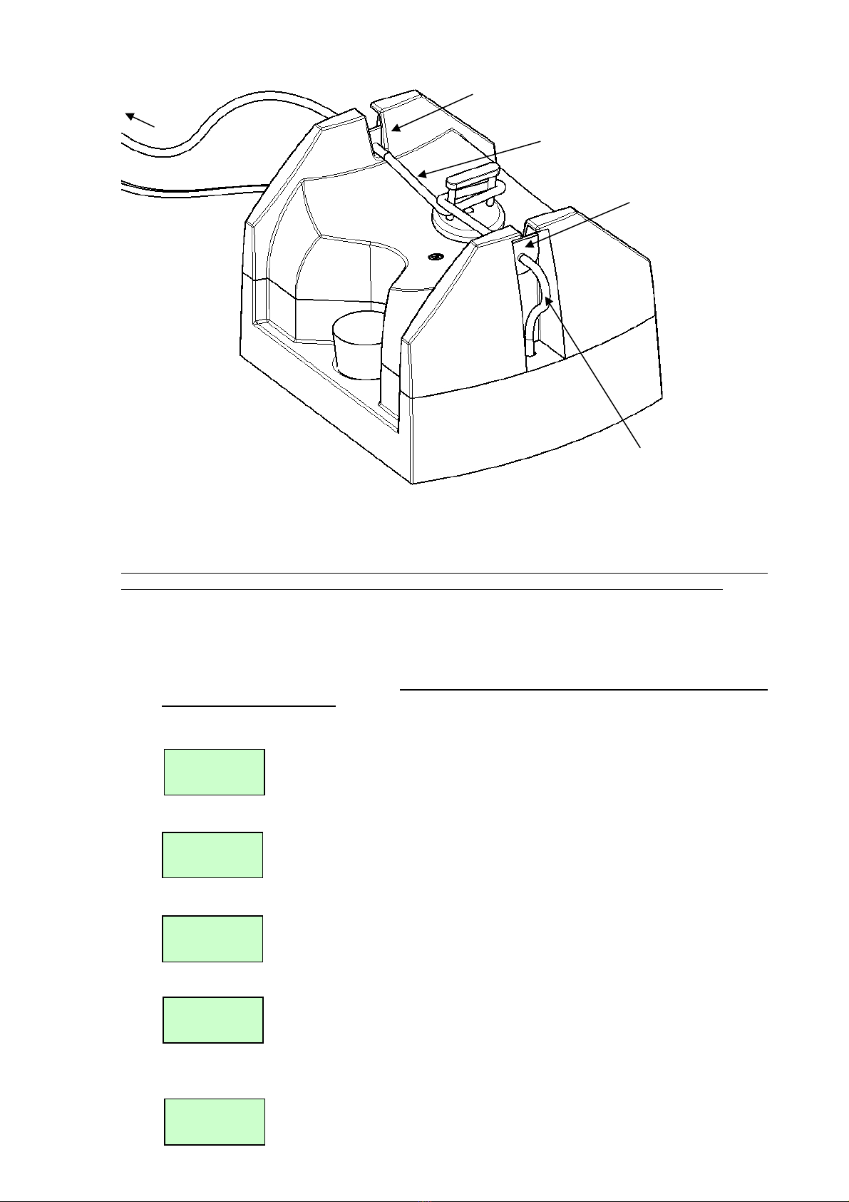
9.1 Changing the pump tube:-
The peristaltic pump will need to have its tube replaced about every 3 months. Cut a length of tube to
about 140mm. Remove the connectors and pull off the old tube. Replace with the new tube, avoiding
twists. Use the diagram on the product label to thread the tube exactly as shown over the pump head. The
tension must be sufficient to ensure complete occlusion of the tube without unnecessary flattening
between the pump rollers. Adjust tube length as necessary. Ensure that the tube does not stick together if
left for long periods by unhooking it during storage.
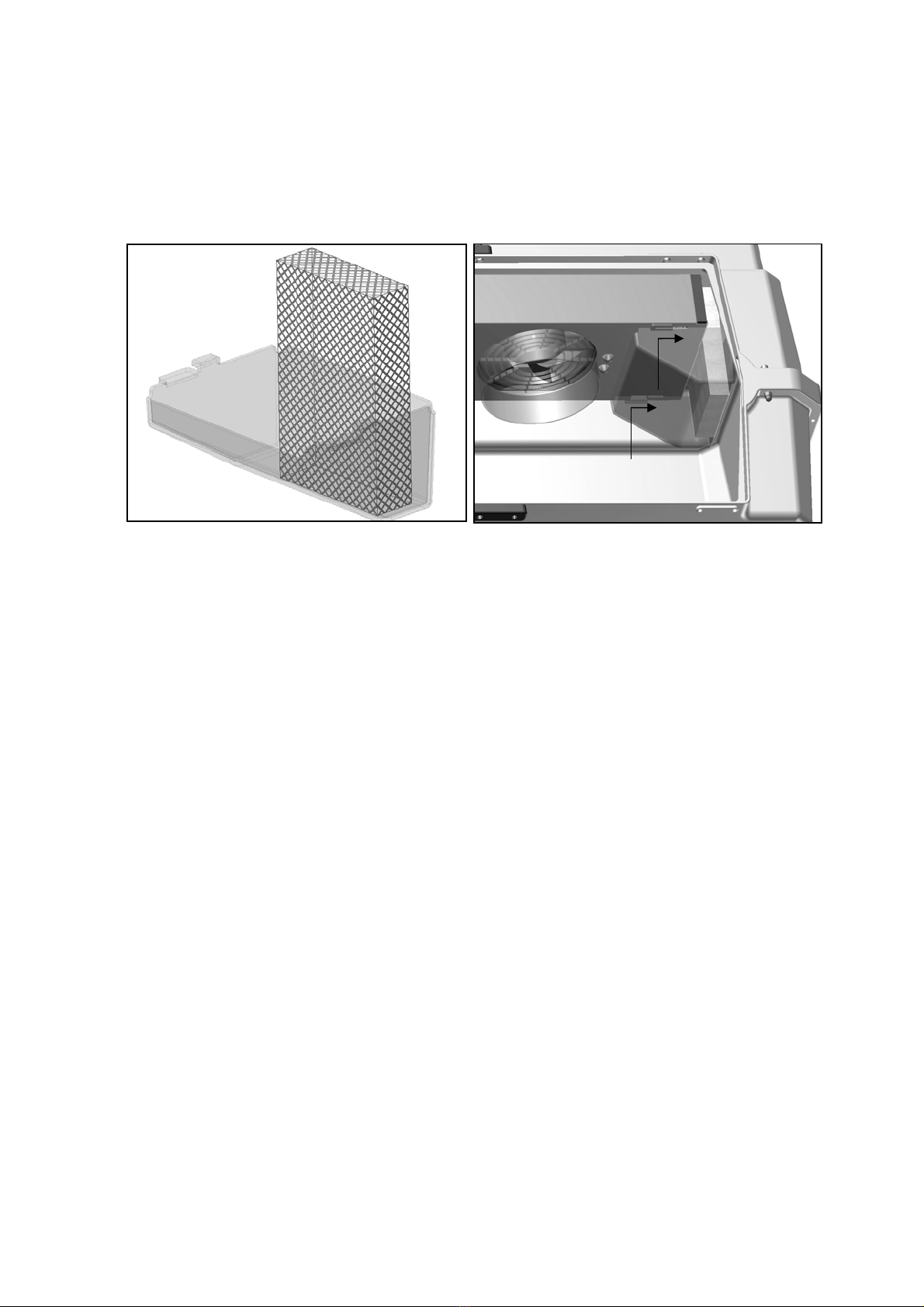
9.2 Changing the evaporation block:-
Change the block as necessary to maintain good evaporating efficiency. Change the block regularly to
avoid bacterial contamination.
9.3 No lubrication or further servicing is required beyond the instructions above.
10 Troubleshooting
The control system may be set to control between 20 and 80% RH. In practice the minimum and maximum
levels of humidity achievable depend upon several factors, particularly the fresh air ventilation rate. You may
need to allow 24 hours for humidity to stabilise after making changes.
If you cannot get the level of RH you want, consider these notes:
10.1 Humidity will not go low enough:-
First increase the fresh air ventilation level. This will help to dilute the moisture given up by the eggs or
animals. There will still remain a lower limit determined by the moisture content of the ambient air,
particularly in warm humid conditions. This can only be countered by dehumidification of the room air
outside the incubator with proprietary dehumidifier but is rarely a problem in practice except with ratites.
10.2 Humidity will not go high enough:-
Restrict fresh air ventilation to the minimum safe level. Remember even embryos need to breathe!
Check that water is reaching the evaporation block when the pump runs – if not check the whole length of
the tubing for kinks and check that the tubing around the pump has not become permanently flattened. If
it has, replace the pump tube. Silicone tubing is very flexible but can be damaged by sharp finger nails. A
tiny perforation on the suction side of the pump will let in air and prevent the pump drawing water.

AD25 GB Issue 03
9
11 Servicing and Calibration
11.1 In case of failure first check the signal cable is securely connected to the incubator / brooder / intensive
care unit.
11.2 Note that the pump will not run if the temperature in the cabinet is below the low temperature alarm point
(typically 3 degrees C. below set temperature).
11.3 The pump motor will only operate when an asterisk “*” is shown next to the RH% display. If this is not
shown check the Set Humidity Level referring to section 5. The asterisk and pump output are only on
when the measured humidity is lower than the Set Humidity Level. The pump output is switched on
intermittently once the measured humidity is within a few percent of the Set Humidity Level.
11.4 The pump motor is easily replaced if necessary using basic tools. Instructions are supplied.
11.5 The digital humidity sensor is individually calibrated during manufacture but may be re-calibrated if
required. It is not recommended that this procedure is carried out by the user.
BE CAUTIOUS OF LOW COST ANALOGUE OR DIGITAL HYGROMETERS. BRINSEA
PRODUCTS USES SOPHISTICATED EQUIPMENT TRACEABLE TO INTERNATIONAL
REFERENCE STANDARDS.
Refer to the incubator, brooder or intensive care unit instructions for details on calibration technique.
11.6 Spare evaporation blocks and silicone tube are available from Brinsea Products Ltd at the address below.
12 Specification
Sensor: Sensor accuracy +/- 3%. Hysteresis 0% R.H
Response time less than 4 seconds
Water Transfer: In-built peristaltic pump
Maximum water flow rate 30g/hour
Tank Capacity: 1L
Control setting and metering: Indicated in % RH (linear)
Dimensions: 15cm x 12.5cm x 14cm (W x D x H)
Weight (dry): 0.6 Kg
Brinsea Products Ltd, Station Road, Sandford, N. Somerset, BS25 5RA
Tel: 0845 226 0120 Fax: (01934) 820250
Table of contents
Other Brinsea Water Pump manuals
Popular Water Pump manuals by other brands

Grundfos
Grundfos CR 32 Service manual

Grundfos
Grundfos Conlift1 LS Installation and operating instructions

ViscoTec
ViscoTec Preeflow eco-PEN700 3D Operation & maintenance manual

HNP Mikrosysteme
HNP Mikrosysteme mzr-4622 operating manual

Agilent Technologies
Agilent Technologies TriScroll 320 Series Installation and operation manual

EINHELL
EINHELL GC-WW 6036 Original operating instructions