Bristol A Series Installation and maintenance instructions

REVISED: 5/03
SUPERSEDES: 2/98
A&BSERIES
INSTALLATION & SERVICE INSTRUCTIONS
REFRIGERATION/AIR CONDITIONING/HEAT PUMP COMPRESSORS
BRISTOL COMPRESSORS, INC.
BRISTOL, VIRGINIA 24202
(276) 466-4121
FAX (276) 645-2423
WARNING
ALWAYS MEASURE START WINDING CURRENT ON START-UP!
NORMALLY 2 to 10 AMPS (See Page 5 for Details)
AND
BEFORE A SUSPECT COMPRESSOR IS REMOVED, ALWAYS
CHECK LOCKED ROTOR PULL-DOWN VOLTAGE
(See Page 2 for Details)
CAUTION: Bristol compressors are completely interchangeable with other
manufacturers. However, electrical specifications, tubing configurations,
and wiring connections may vary. Before installing and starting this
compressor, you must review the wiring diagrams and check for correct
electrical components.

Page 2
WARNING: Read all procedures and warnings prior to performing maintenance! For your
safety, it is essential that you use properly sized and operating test equipment.
INSTALLATION PROCEDURES AFTER COMPRESSOR HAS BEEN VERIFIED AS FAULTY…
BEFORE CONDEMNING A SINGLE-PHASE COMPRESSOR THAT FAILS TO START…
1. Verify all following components are OK:
A. Run capacitor
B. Starting components (even if not originally installed, start assist should be tried before going to step 2)
C. Contactor
D. Winding resistance within manufacturer’s specification (assure compressor is cool to the touch)
E. Compressor not grounded via ohmmeter/Megger, etc.
F. Compressor power terminals are tight and secure
G. Check for hot spots in system wiring (wire insulation melted, connectors, insulators melted, etc.)
2. Verify locked rotor pull-down voltage (LRPDV). Always check LRPDV before removing the old or new
replacement compressor. If the LRPDV reduces the supply voltage to the compressor below the
“guaranteed to start” voltage of the compressor (single-phase 230/208 LRPDV is 197v), the power supply
must be corrected before removing the compressor.
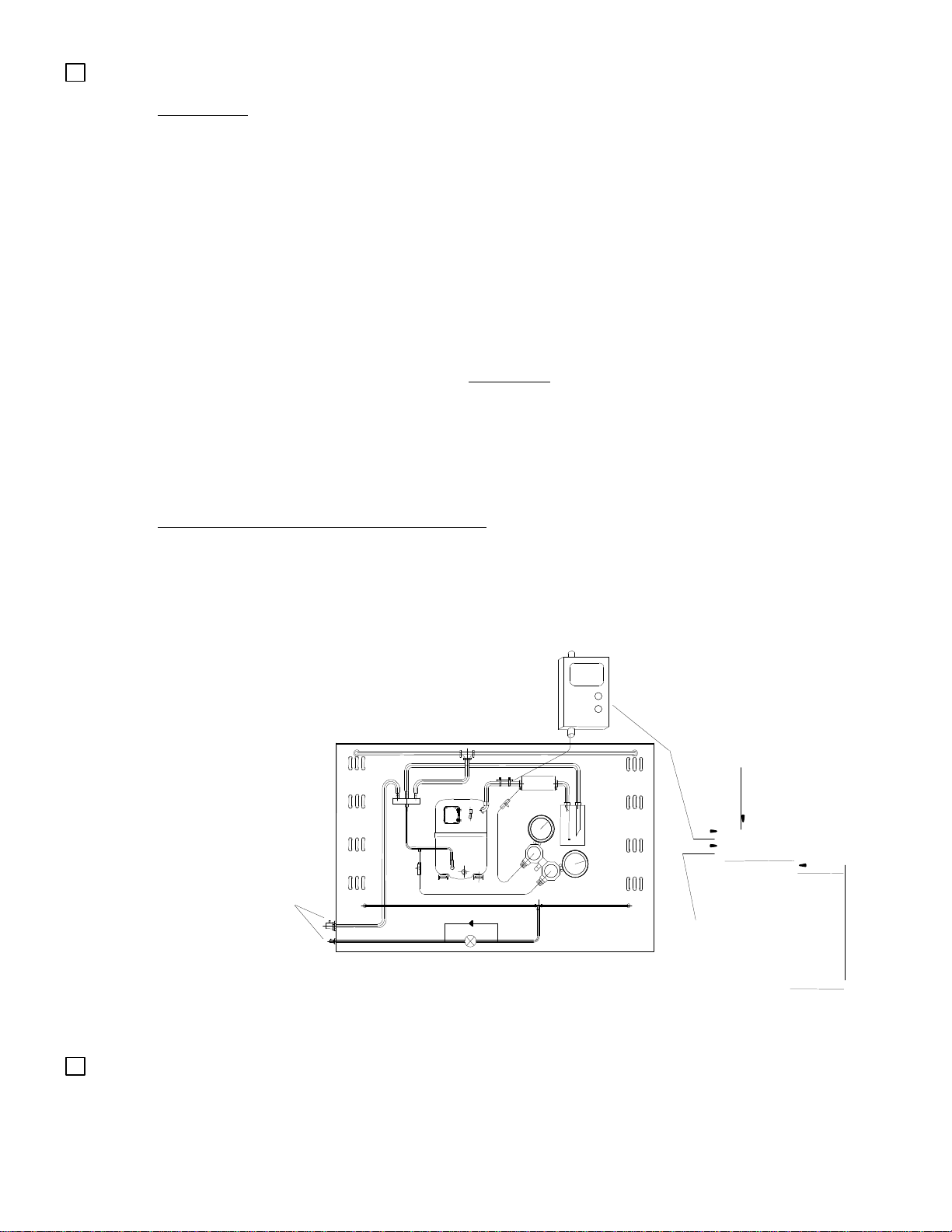
Procedure to check for LRPDV: Warning! Make sure system is properly grounded before
proceeding!
A. Connect a voltmeter to the common terminal and run terminal of the compressor.
B. Remove the start wire from the compressor and insulate the connector lead wire.
C. Terminal cover and retainer MUST be installed before applying voltage. (See warning on page 4.)
D. Apply voltage to the compressor and measure the voltage as the compressor attempts to start (during
locked rotor). If internal overload trips, allow time for reset before continuing.
E. If the voltage at the compressor terminals does not pull down below the LRPDV, reconnect the start
wire and try to start again. If the compressor does not start, proceed to step 3 below.
3. Direct wiring. This wiring eliminates all other components and system wiring.
A. Hard-wire from a fused disconnect to the Cand Rterminals of the compressor
B. Wire in a new run capacitor from the Sterminal to the Rterminal at the compressor using new wire
leads (see page 9 permanent split capacitor-wiring diagram)
C. Turn on disconnect, verify LRPDV and measure start winding current (see item 10, page 5)
D. If compressor does not start, add a two-wire start assist kit in parallel with the run capacitor and repeat
step 3 (C). If the pressures are equalized and the LRPDV and start current are OK, and the
compressor still does not start, it is definitely faulty.
The following instructions are general in nature but include major points of consideration that will ensure proper
installation and protect you from possible personal injury. Please use this as a checklist, taking each item in its order
before proceeding to the next. If more information is required, please call Bristol Compressors’ Service Department.
1. VERIFY PROPER APPLICATION. Verify that the compressor being replaced and the Bristol compressor
have a like capacity for the refrigerant being used and that the voltage and frequency characteristics are
the same. Consult your wholesaler if you have any questions about proper compressor application.
WARNING: Never use oxygen to pressurize a refrigeration or air conditioning system.
Oxygen can explode on contact with oil and could cause personal injury. When using high
pressure gas such as nitrogen or CO2for this purpose, be sure to use a regulator that can
control the pressure down to 1 or 2 psig.
WARNING: Air conditioning and refrigeration systems are pressurized; hazards could exist
resulting in personal injury. It is therefore recommended that the following steps for
troubleshooting, removal and installation of the hermetic compressor be performed by
qualified experienced personnel only.

Page 3
2. DETERMINE CAUSE OF INITIAL FAILURE. In order to prevent a second failure, the cause of the
original failure must be determined. Identify the cause and make the necessary repairs.
A. BEFORE REMOVING THE FAULTY COMPRESSOR: Remove refrigerant charge using proper
recovery procedures. Call 1-800-441-9450 for the name of the nearest Dupont authorized distributor,
or 1-800-631-8138 for Genetron Representative or 1-800-ASK-KLEA (ICI) for information on
refrigerant reclaim programs.
B. Remove the electrical leads from the compressor. Note and label the terminal to which each wire is
connected.
C. During the next operation, the access ports should be open so that pressure does not build up in the
system. Use a high temperature torch to sweat the suction line and the discharge line loose from the
compressor.
D. Remove the faulty compressor.
E. Assure excessive oil does not remain in the system. Measure oil in the failed compressor and,
if oil is low, flush excess from system (or see alternative below).
Good indicators of excess oil are: violent vibration and/or high variable sound as the extra oil moves
through the system.
Alternatives: If the excess oil cannot be flushed from the system, the last alternative is to reduce the
oil charge in the new compressor by the amount left in the system.
•This procedure should be used only if the following are true:
-The oil remaining in the system is dry (i.e., system had not leaked down)
-Oil type is same as in the replacement compressor
-Compressor failure was not a motor burnout
-The oil remaining in the system is less than 50% of the original oil charge
-Suction filter drier must be installed
•Procedure if failed compressor has lost more than 50% of the original oil charge
-Operate new compressor for 15 minutes in cooling mode (30 minutes if a suction line
accumulator is installed)
-Recover refrigerant and remove the compressor
-Remove oil from the compressor and recharge with fresh oil per the manufacturer’s
specifications
E. Remove the faulty compressor.
CAUTION: The compressor may contain harmful acids be sure to handle with extreme care using
proper protection equipment. After confirming oil charge level, return oil to compressor and install
suction and discharge rotalock caps. Copper tube fittings should be brazed closed. This is needed to
prevent further contamination of the compressor and to prevent spillage from the compressor.
3. MOUNT THE NEW COMPRESSOR. Do not remove dust cover or rubber shipping plugs until all other
connections have been completed (i.e., filters installed and all tubing changes made see steps 4, 5 and
6). Compressor should not be open to the atmosphere for more than 15 minutes. Be sure to use the new
mounting grommets that were shipped with the compressor. If the mounting sleeves shipped with the
compressor are used, the mounting bolts will bottom out when tight. Use care not to over-compress the
mounting grommets when the mounting sleeves cannot be used.
4. INSTALL FILTER DRIERS. Bristol Compressors recommends the use of new adequately sized liquid and
suction line driers anytime a compressor is replaced. If the new compressor is to be used to replace a
compressor with a burned motor, the use of a high acid neutralizing filter drier is recommended. For heat
pumps, a suction filter drier must be installed between the accumulator and the compressor suction
WARNING: To avoid electrical shock, power to the compressor sh
ould remain off during
performance of Steps 2 through 10.

Page 4
inlet. In addition, a bi-directional heat pump liquid line drier or factory recommended driers must be
installed. NOTE: ALWAYS REMOVE OLD FILTER DRIERS.
5.BRAZE ON SUCTION AND DISCHARGE LINES. Flow an inert gas, such as nitrogen or CO2, through the
system at approximately 2 psig. This will reduce the possibility of oxidation inside the tubing. Braze on the
suction and discharge lines and braze the process tube shut following the recommendation listed below (if
the process tube is to be used, it should be brazed shut after the system has been charged):
COPPER TUBING: If additional copper tubing is required, use only clean, dehydrated refrigeration
grade tubing with sealed ends.
BRAZING ALLOYS: CAUTION: Do not use 95/5, 50/50 or 40/60 soft solder for brazing.Use Sil-Fos or
Phos Copper, or similar brazing alloys with high tensile strength on copper
welds only. Weld steel to copper only with silver brazing alloys.
BRAZING PROCEDURE: To ensure properly brazed joints, Bristol Compressors recommends that the
following steps be used:
a. Exercise extreme care when cutting and forming tubes to keep dirt, filings,
and other contaminants from entering the system.
b. Do not use excessive amounts of brazing alloy as some of the excess may
penetrate the joint and enter the system.
c. If flux must be used, take necessary precautions to ensure that the flux does
not enter the system.
d. Use damp cloths or other heat absorbent material to ensure that the factory-
brazed joints on the compressor do not become damaged. If damp cloths
are used, take care not to allow moisture to enter the system.
e. Do not overheat brazed joints as excess heat will cause formation of copper
oxide on the inside wall of the tubing. Flow an inert gas through the system,
as explained above.
6. CHECK SYSTEM FOR LEAKS. After installation is complete, pressurize the system to 75 psig using
nitrogen and a few ounces of system refrigerant. Check for leaks using a halide torch, soap bubbles or an
electronic halogen leak detector. When all connections test satisfactorily, release pressure using proper
recovery procedures, then proceed to next step.
7. EVACUATE THE SYSTEM. Use a vacuum pump designed for this purpose. Vacuum must be pulled on
the discharge (high side) and suction (low side) of the system. Evacuate to 200 microns or lower.
8. CHECK THE ELECTRICAL SYSTEM. While the system is evacuating, connect the electrical leads to the
compressor terminals. Verify that the electrical system is wired according to the unit’s manufacturer and
Bristol’s wiring diagram on page 9. Verify that the electrical components match those specified on the
compressor electrical data sheet on pages 10 through 14. Start components (start capacitor and relay)
are required on all systems that incorporate a hard shut-off or non-bleed thermostatic expansion
valve. It is a normal practice to replace all starting components any time a compressor is changed. Check
all connections and terminals to be sure they are tight. Connect the crankcase heater (standard on all “A”
Series). Power to the crankcase heater must be energized continuously. Voltage to an insertion type
heater can be anything between 187 to 600 volts. Operational voltage for wrap-around type heaters must
be verified.
CAUTION: Do not use the Bristol replacement compressor as an evacuation assist and never
apply voltage to a compressor while it is in a vacuum as damage could result.
WARNING: Application of voltage to the compressor with the terminal cover and retainer removed
can result in serious personal injury or death.

Page 5
9. CHARGE THE SYSTEM. When a vacuum of at least 200 microns is reached, close gauge valve, remove
vacuum pump, and break the vacuum using system refrigerant vapor. Never dump liquid refrigerant into
the compressor. Liquid can be used to break the vacuum if it is connected to the liquid line, not the
discharge line.
Charge the system according to the manufacturer’s specifications. Be sure to compensate the charge for
the addition of the filter drier. Consult unit pressure/superheat chart on the unit door panel for the correct
superheat since pressures and superheat change with the ambient temperature.
WEIGHING in the system charge to the factory specification will help point out system faults that
may still exist.
10. START-UP. CLAMP-ON AMMETER MUST BE IN PLACE BEFORE POWER IS APPLIED TO MONITOR
START WINDING CURRENT ON START-UP!! See page 6
ASSURE THESE NORMAL START WINDING CURRENTS ON START-UP
CONFIGURATION APPROX. CURRENT
NORMAL START WITH RUN CAP ONLY 2 -10 AMPS
NORMAL START WITH RUN AND START CAP 20 AMPS AND DROP TO 2-10 AFTER START
NORMAL START WITH START CAP (INDUCTION RUN) 20 AMPS AND DROP TO 0 AFTER START
WARNING: If above currents are exceeded for more than 5 seconds, disconnect power and
correct the fault before restarting.
NOTE: Assure voltage to compressor does not drop below minimum allowable voltage (eg. 197
volts for 230/208-1-60) during the period the compressor is trying to start. Refer to page 2
for explanation of test to check LOCKED ROTOR PULL-DOWN VOLTAGE.

Page 6
FOR CAPACITOR START/CAPACITOR RUN (CSR) MODELS
FOR CAPACITOR START INDUCTION RUN (CSIR) MODELS
5
2
1
LINE
LINE
START
CAPACITOR
RUN
CAPACITOR POTENTIAL
RELAY
IDENTIFIED
TERMINAL
TO LINE SIDE
BLEED
RESISTOR
C
PUT YOUR CLAMP-ON AMMETER HERE
AMPS SHOULD DROP TO
"0" AFTER START
S
R
RUN
WINDING
START
WINDING
5
2
1
LINE
POTENTIAL
RELAY
BLEED
RESISTOR
START
CAPACITOR
PUT YOUR CLAMP-ON AMMETER HERE
AMPS SHOULD DROP TO "0"
AFTER START
START
WINDING
LINE
C
S
R
RUN
WINDING

Page 7
11. VERIFY SYSTEM WILL NOT ALLOW LIQUID FLOODBACK.
HEAT PUMP
STEP 1: Operate system in the heating mode with outdoor fan disconnected.
STEP 2: Run system until the designed winter condition in your area is reached (may need to cover coil for
this test).
STEP 3: Check suction superheat 6” from compressor inlet.
STEP 4: Superheat should not drop below 5°F (3°K) (prefer no lower than 10°F [6°K]).
STEP 5: Sump temperature should always be 50°F (28°C) or higher above saturated suction temperature.
EXAMPLE: “R-22”
38 psig = 16°F (-9°C) = SATURATED SUCTION
+ 50°F (28°K) = MINIMUM TEMP. DIFFERENCE
66°F (19°C) = MINIMUM SUMP TEMPERATURE
COOLING MODE (HEAT PUMP)
STEP 1: Operate system in cooling mode with indoor fan disconnected and repeat steps 3, 4 and 5.
AIR-CONDITIONING/REFRIGERATION UNITS
STEP 1: Operate system in the cooling mode with indoor fan disconnected and repeat steps 3, 4 and 5.
TAKE SUCTION
TEMPERATURE
6" TO 12"
FROM COMPRESSOR
NOTE:
58° F (14°C)
-
38° F (
-
3°C)
20° F (11°K)
FOR THE “HARD TO GET
TO” COMPRESSOR
TAKE TEMPERATURES
AND PRESSURES HERE,
AIR CONDITIONING
MODE ONLY
CONVERT SUCTION
PRESSURE TO
TEMPERATURE
65 PSIG = 38°F (3°C)
SUPERHEAT
HOW TO CHECK SUPERHEAT
58°F
DIGITAL
THERMOMETER
(14°C)
12. CHECK FILTER DRIERS FOR CONTAMINATION.
A. Suction Line Filter: If internal contamination is heavy, the suction line filter drier may become
clogged and ineffective. Check the pressure drop across the filter drier after approximately 8 hours
running time and, if it exceeds 2 psig, replace.

Page 8
B. Liquid Line Filter: Always replace the original equipment liquid line filter drier(s). If the OEM liquid
line drier(s) is not removed from the system, a restriction most likely will result. A slight restriction in
this filter will reduce the efficiency of the system. A large restriction will cause the suction pressure
and discharge pressure to be reduced. This reduction in pressure will occur only with a properly
charged system (i.e., refrigerant weighed in to the OEM specifications). An over-charged system will
increase pressures when there is a restriction in the liquid line. The service person tends to add
more charge to the system to increase the suction pressure. Normally, any charge added above the
OEM specifications will increase the suction pressure due to the discharge pressure increasing but in
the case of a restriction, charge can be added to a point the system shuts down on the high pressure
limit switch. The service person may not see the higher discharge pressure due to his service port
being in the liquid line which is normally downstream from the liquid line filter drier in residential split
systems. A pressure port installed in the hot gas discharge line just as it exits the compressor is
required to see true discharge pressure.
C. Discharge Line Filter: Some OEM equipment may have a filter in the hot gas line (6” –12” from
compressor). Checks outlined in (B) above apply.
IMPORTANT: The compressor has an internal relief valve (IPRV) that is designed to open if the
system is subjected to a high pressure situation. Example causes are: overcharged, air in system,
restriction, factory-installed metering device screens not removed and cleaned, old liquid line filter left
in the system, poor airflow across the condenser, condenser fan failure, poor airflow across the
evaporator in the heating mode (dirty return air filter(s)), poor system design (duct system
undersized), etc. The IPRV will open when the discharge pressure exceeds the suction pressure by
more than 450 psi (“B” products) or 400 psi (“A” products). If the relief valve opens, a high velocity
gas flow may be heard inside the compressor housing. In some cases, the relief valve may open so
quickly due to a restriction in the system, the high pressure will be difficult to observe on standard
gauges. In most instances, if the service person installs a discharge service gauge on the discharge
line just as it exits the compressor, the development of high pressure can be observed before the
relief valve opens. Installing the discharge service gauge on the liquid line outside the system may
not detect a restriction. To reset the relief valve, shut the compressor off for at least 5 minutes,
allowing pressures to equalize.
RREVIEW ALL TWELVE STEPS TO MAKE SURE NOTHING WAS OVERLOOKED.

Page 9
S
5
2
1
LINE
START
CAPACITOR
RUN
CAPACITOR
POTENTIAL
RELAY
IDENTIFIED
TERMINAL TO
LINE SIDE
BLEED
RESISTOR
LINE
IDENTIFIED
TERMINAL TO
LINE SIDE
RUN
CAPACITOR
LINE
IDENTIFIE
D
TERMINAL
TO LINE SIDE
RUN
CAPACITOR
LINE
CS
R
RUN
WINDING
START
WINDING
LINE
CS
R
RUN
WINDING
START
WINDING
LINE
C
R
RUN
WINDING
START
WINDING
START ASSIST WIRING DIAGRAM (START AND RUN CAPACITORS):
Use this diagram on systems with expansion valve and systems that do not allow pressure equalization
prior to compressor start.
NOTE
: WHEN CRANKCASE HEATER IS USED, CONNECT TO INCOMING POWER LINE SO THAT
HEATER IS ENERGIZED CONTINUOUSLY.
PERMANENT SPLIT CAPACITOR (PSC) WIRING DIAGRAM:
Use this diagram on systems that allow pressure equalization prior to compressor start.
NOTE: WHEN CRANKCASE HEATER IS USED, CONNECT TO INCOMING POWER LINE SO
THAT HEATER IS ENERGIZED CONTINUOUSLY.
START ASSIST WIRING DIAGRAM (PTCR AND RUN CAPACITOR):
PTCR
Use this light start assist in case of a slight low voltage condition with equalized pressures prior to
compressor start.
NOTE: SOFT START ASSIST (PTCR) IS REQUIRED ON SOME HIGH EFFICIENCY COMPRESSORS
(SEE PAGE 12) EVEN WHEN THE SYSTEM EQUALIZES. “C” IN THE 8TH-DIGIT OF MODEL NUMBER
IDENTIFIES COMPESSORS THAT REQUIRE PTCR START ASSIST. NOT REQUIRED WHEN A
START ASSIST KIT IS USED (RELAY, START CAPACITOR).

Page 10
AIR CONDITIONING & HEAT PUMP ELECTRICAL
COMPONENTS PARTS FOR SINGLE PHASE
COMPRESSORS
H24B SERIES 60 HZ
Capacitors Potential Relays
Mars
Compressor
Model Number
Voltage
Phase
Hz Run
µfd/Volts
Start
µfd/Volts GE
3ARR3 6-Pak
OEM PTCR
Starter
H24B13QABCA
230/208-1-60
15/370 88-108/250
3U 66 16049
Optional
H24B13QABCB
230/208-1-60
15/370 88-108/250
3U 66 16049
Optional
H23B SERIES 60 HZ
Capacitors Potential Relays
Mars
Compessor
Model Number
Voltage
Phase
Hz Run
µfd/Volts Start
µfd/Volts GE
3ARR3 6-Pak
OEM PTCR
Starter
H23B15QABC 230/208-1-60 25/370 88-108/250 3T 69 16068 Optional
H23B15QABH 265-1-60 20/440 88-108/330 10T 69 16073 Optional
H23B17QABC 230/208-1-60 25/370 88-108/250 3P 65 16050 Optional
H23B17QABH 265-1-60 25/370 88-108/330 10U NA NA Optional
H23B19QABC 230/208-1-60 25/370 88-108/250 10S 69 16067 Optional
H23B20QABC 230/208-1-60 25/370 88-108/250 10S 69 16067 Optional
H23B22QABC 230/208-1-60 30/370 88-108/250 10S 69 16067 Optional
H23B22QABH 265-1-60 25/440 88-108/250 25U 66 NA Optional
H23B24QABC 230/208-1-60 35/370 88-108/250 24P 69 16072 Optional
H23B26QABC 230/208-1-60 35/370 88-108/250 3P 65 16050 Optional
H23B28QABC 230/208-1-60 35/370 88-108/250 10S 69 16067 Optional
H23B28QABH 265-1-60 30/440 88-108/330 10S 69 16067 Optional
H23B30QABC 230/208-1-60 40/370 88-108/250 24P 69 16072 Optional
H23B32QABC 230/208-1-60 45/370 88-108/250 3L NA 16083 Optional
H29B SERIES 60 HZ
Capacitors Potential Relays
Mars
Compressor
Model Number
Voltage
Phase
Hz Run
µfd/Volts Start
µfd/Volts GE
3ARR3 6-Pak
OEM PTCR
Starter
H29B14UABC 230/208-1-60 30/370 161-193/250
3V 66 16048 Optional
H29B15UABC 230/208-1-60 30/370 161-193/250
3V 66 16048 Optional
H29B16UABC 230/208-1-60 30/370 161-193/250
3V 66 16048 Optional
H29B17UABC 230/208-1-60 30/370 161-193/250
3V 66 16048 Optional
H29B17UABH 265-1-60 25/440 88-108/330 10U NA NA Optional
H29B18UABC 230/208-1-60 30/370 161-193/250
3V 66 16048 Optional
H29B18UABH 265-1-60 25/440 88-108/330 10U NA NA Optional
H29B20UABC 230/208-1-60 30/370 145-175/250
3U 66 16048 Optional
H29B20UABH 265-1-60 30/440 88-108/330 10S 69 16067 Optional
H29B22UABC 230/208-1-60 30/370 145-175/250
3U 66 16049 Optional
H29B22UABH 265-1-60 30/440 88-108/330 10S 69 16067 Optional
H29B24UABC 230/208-1-60 35/370 145-175/250
3T 69 16068 Optional
H29B24UABH 265-1-60 30/440 88-108/330 10S 69 NA Optional
H29B26UABC 230/208-1-60 35/370 145-175/250
3T 69 16068 Optional
H29B26UABH 265-1-60 30/440 88-108/330 10S 69 NA Optional
H29B28UABC 230/208-1-60 35/370 145-175/250
3T 69 16068 Optional
H29B28UABH 265-1-60 30/440 88-108/330 10S 69 NA Optional
H29B30UABC 230/208-1-60 40/370 145-175/250
3P 65 16050 Optional
H29B30UABH 265-1-60 30/440 88-108/330 10S 69 NA Optional
NOTE: Eleventh character of the model number represents the foot configuration
–could be A or B.
PROCESS
DISCHARGE
CRANKCASE HEATER
RECEPTACLE (THIS END)
SUCTION
H24B, H29B
SUCTION
PROCESS
DISCHARGE
CRANKCASE HEATER
RECEPTACLE (THIS END)
H23B

Page 11
AIR CONDITIONING & HEAT PUMP ELECTRICAL COMPONENTS
PARTS FOR SINGLE PHASE COMPRESSORS
H29B SERIES 60 HZ (Continued)
Compressor Voltage Capacitors Potential Relays
MarsModel Number Phase Hz Run
µfd/Volts Start
µfd/Volts GE
3ARR3 6-Pak
OEM PTCR
Starter
H29B32UABC 230/208-1-60 40/370 145-175/250
3P 65 16050
Optional
H29B32UABH 265-1-60 30/440 88-108/330 10S 69 NA Optional
H29B33UABC 230/208-1-60 45/370 243-292/250
3V 66 16048
Optional
H29B33UABH 265-1-60 30/440 88-108/330 10S 69 NA Optional
H29B35UABC 230/208-1-60 45/370 145-175/250
3N 16082
Optional
H29B35UABH 265-1-60 35/440 88-108/330 10S 69 NA Optional
H29A SERIES 60 HZ
Capacitors Potential Relays
Mars
Compressor
Model Number
Voltage
Phase
Hz. Run
µfd/Volts Start
µfd/Volts GE
3ARR3 6-Pak
OEM PTCR Starter
H29A323CBC
230/208-1-60
40/370 270-324/330
3S NA 16055
305C20
H29A353CBC
230/208-1-60
40/370 270-324/330
3S NA 16055
305C20
H29A383CBC
230/208-1-60
45/370 270-324/330
3S NA 16055
305C20
H29A403CBC
230/208-1-60
45/370 270-324/330
3P NA 16054
305C19
H29A423CBC
230/208-1-60
45/370 270-324/330
3P NA 16054
305C19
H29A443CBC
230/208-1-60
45/370 270-324/330
3P NA 16054
305C9
H29A473CBC
230/208-1-60
55/370 270-324/330
3N NA 16053
305C19
H29A503CBC
230/208-1-60
55/370 270-324/330
3N NA 16053
305C19
H29A543CBC
230/208-1-60
60/370 270-324/330
3N NA 16053
305C9
H29A563CBC
230/208-1-60
60/370 270-324/330
3N NA 16053
305C9
H29A583CBC
230/208-1-60
60/370 270-324/330
24R NA 16057
305C19
H29A623CBC
230/208-1-60
60/370 270-324/330
24R NA 16057
305C9
H23A SERIES 60 HZ
Capacitors Potential Relays
Mars
Compressor
Model Number
Voltage
Phase
Hz. Run
µfd/Volts Start
µfd/Volts GE
3ARR3 6-Pak
OEM PTCR Starter
H23A353ABC
230/208-1-60
35/440 145-175/250
4A 64 16047
Optional
H23A383ABC
230/208-1-60
35/440 145-175/250
4A 64 16047
Optional
H23A423ABC
230/208-1-60
40/440 145-175/250
4A 64 16047
Optional
H23A463ABC
230/208-1-60
40/440 135-155/330
4A 64 16047
Optional
H23A503ABC
230/208-1-60
40/440 135-155/330
4A 64 16047
Optional
H23A543ABC
230/208-1-60
45/440 135-155/330
4A 64 16047
Optional
H23A563ABC
230/208-1-60
55/440 135-155/330
6U 66 16062
Optional
H23A623ABC
230/208-1-60
55/440 135-155/330
4A 64 16047
Optional
H24A SERIES 50 HZ
Capacitors Potential Relays
Mars
Compressor
Model Number
Voltage
Phase
Hz. Run
µfd/Volts Start
µfd/Volts GE
3ARR3 6-Pak
OEM PTCR Starter
H24A383ABK
220/240-1-50
40/440 145-175/330
4AA NA NA Optional
H24A423ABK
220/240-1-50
40/440 145-175/330
4AA NA NA Optional
DISCHARGE
SUCTION
PROCESS
CRANKCASE HEATER
RECEPTACLE
H23A, H29A

Page 12
H24B SERIES 50 HZ
Capacitors Potential Relays
Mars
Compressor
Model Number
Voltage
Phase
Hz. Run
µfd/Volts Start
µfd/Volts GE
3ARR3 6-Pak
OEM PTCR Starter
H24B15QABH
220/240-1-50
20/370 88-108/250 10AT NA NA Optional
H24B17QABH
220/240-1-50
25/370 88-108/250 10AT NA NA Optional
H24B19QABK
220/240-1-50
25/370 88-108/330 25AS NA NA Optional
H24B SERIES 50 HZ (Continued)
Capacitors Potential Relays
Mars
Compressor
Model Number
Voltage
Phase
Hz. Run
µfd/Volts Start
µfd/Volts GE
3ARR3 6-Pak
OEM PTCR Starter
H24B20QABK
220/240-1-50
25/370 88-108/250 6AW NA NA Optional
H24B22QABH
220/240-1-50
30/370 88-108/250 25AS NA NA Optional
H24B24QABH
220/240-1-50
35/370 88-108/250 25AS NA NA Optional
H24B26QABH
220/240-1-50
35/370 88-108/250 25AS NA NA Optional
H24B28QABH
220/240-1-50
40/370 88-108/250 25AS NA NA Optional
H24B29QABK
220/240-1-50
40/370 88-108/250 24AP NA NA Optional
H24B31QABK
220/240-1-50
45/370 88-108/250 25AS NA NA Optional
H24B32QABK
220/240-1-50
45/440 88-108/250 25AS NA NA Optional
H25B SERIES 50 HZ
Capacitors Potential Relays
Mars
Compressor
Model Number
Voltage
Phase
Hz. Run
µfd/Volts Start
µfd/Volts GE
3ARR3 6-Pak
OEM PTCR Starter
H25B17QABH
220/240-1-50
30/370 145-175/250
10S 69 16067
Optional
H25B18QABH
220/240-1-50
30/370 145-175/250
10S 69 16067
Optional
H25B22QABH
220/240-1-50
30/440 145-175/250
10U NA NA Optional
H25B24QABH
220/240-1-50
35/370 145-175/250
10U NA NA Optional
H25B26QABH
220/240-1-50
40/370 145-175/250
10S 69 16067
Optional
H25B28QABH
220/240-1-50
40/370 145-175/250
10S 69 16067
Optional
H25B30QABH
220/240-1-50
40/370 145-175/250
10S 69 16067
Optional
H25B32QABH
220/240-1-50
40/370145-175/250
10S 69 16067
Optional
H25B35QABH
220/240-1-50
45/370 145-175/250
10S 69 16067
Optional
H28A SERIES 50 HZ
Capacitors Potential Relays
Mars
Compressor
Model Number
Voltage
Phase
Hz. Run
µfd/Volts Start
µfd/Volts GE
3ARR3 6-Pak
OEM PTCR Starter
H28A383ABK
220/240-1-50
50/370 145-175/250
24P 69 16072
Optional
H28A423ABK
220/240-1-50
55/370 145-175/250
24P 69 16072
Optional
H28A473ABK
220/240-1-50
65/440 161-193/250
6AS NA NA Optional
H29B SERIES 50 HZ
Capacitors Potential Relays
Mars
Compressor
Model Number
Voltage
Phase
Hz. Run
µfd/Volts Start
µfd/Volts GE
3ARR3 6-Pak
OEM PTCR Starter
H29B17UABH
220/240-1-50
30/370 145-175/250
10S 69 16067
Optional
H29B18UABH
220/240-1-50
30/370 145-175/250
10S 69 16067
Optional
H29B20UABH
220/240-1-50
35/370 145-175/250
10U NA NA Optional
H29B22UABH
220/240-1-50
35/370 145-175/250
10U NA NA Optional
H29B24UABH
220/240-1-50
40/370 145-175/250
10S 69 16067
Optional
H29B26UABH
220/240-1-50
40/370 145-175/250
10S 69 16067
Optional
H29B28UABH
220/240-1-50
40/370 145-175/250
3L NA 16083
Optional
H29B30UABH
220/240-1-50
40/370 145-175/250
10S 69 16067
Optional
H29B32UABH
220/240-1-50
40/370 145-175/250
10S 69 16067
Optional
H29B33UABH
220/240-1-50
40/370 145-175/250
10S 69 16067
Optional
H29B35UABH
220/240-1-50
45/370 145-175/250
10S 69 16067
Optional

Page 13
H73A SERIES 50 HZ
Capacitors Potential Relays
Mars
Compressor
Model Number
Voltage
Phase
Hz. Run
µfd/Volts Start
µfd/Volts GE
3ARR3 6-Pak
OEM PTCR Starter
H73A263ABH
220/240-1-50
35/370 145-175/250
10AS NA NA Optional
H73A283ABK
220/240-1-50
35/370 145-175/250
10AS NA NA Optional
H73A303ABH
220/240-1-50
35/370 145-175/250
10AS NA NA Optional
H73A323ABH
220/240-1-50
40/370 145-175/250
10AT NA NA Optional
H73A353ABH
220/240-1-50
35/370 145-175/250
25AV NA NA Optional
H73A383ABK
220/240-1-50
35/440 145-175/330
4AA NA NA Optional
H73A423ABK
220/240-1-50
40/440 145-175/330
27AA NA NA Optional
H73A463ABK
220/240-1-50
40/440 145-175/330
4AA NA NA Optional
H23A SERIES 50 HZ
Capacitors Potential Relays
Mars
Compressor
Model Number
Voltage
Phase
Hz. Run
µfd/Volts Start
µfd/Volts GE
3ARR3 6-Pak
OEM PTCR Starter
H23A263ABH
220/240-1-50
35/370 145-175/250
10AS NA NA Optional
H23A283ABK
220/240-1-50
35/370 145-175/250
10AS NA NA Optional
H23A303ABH
220/240-1-50
35/370 145-175/250
10AS NA NA Optional
H23A323ABH
220/240-1-50
40/370 145-175/250
10AT NA NA Optional
H23A353ABH
220/240-1-50
35/370 145-175/250
25AV NA NA Optional
H23A35QABK
220/240-1-50
35/370 145-175/250
25AV NA NA Optional
H23A383ABK
220/240-1-50
35/440 145-175/330
4AA NA NA Optional
H23A38QABK
220/240-1-50
35/370 145-175/250
4AA NA NA Optional
H23A423ABK
220/240-1-50
35/440 145-175/330
27AA NA NA Optional
H23A42QABK
220/240-1-50
40/440 145-175/250
27AA NA NA Optional
H23A463ABK
220/240-1-50
40/440 145-175/330
4AA NA NA Optional
H23A46QABK
220/240-1-50
40/440 135-155/330
4AA NA NA Optional
H23B SERIES 50 HZ
Capacitors Potential Relays
Mars
Compressor
Model Number
Voltage
Phase
Hz. Run
µfd/Volts Start
µfd/Volts GE
3ARR3 6-Pak
OEM PTCR Starter
H23B153ABH
220/240-1-50
25/370 88-108/250 10AS NA NA Optional
H23B15QABH
220/240-1-50
20/370 88-108/250 10AS NA NA Optional
H23B173ABH
220/240-1-50
25/370 88-108/250 10AS NA NA Optional
H23B17QABH
220/240-1-50
25/370 88-108/250 10AS NA NA Optional
H23B17SABH
220/240-1-50
30/370 145-175/250
10AS NA NA Optional
H23B18SABH
220/240-1-50
30/370 145-175/250
10S 69 16067
Optional
H23B193ABK
220/240-1-50
30/370 88-108/250 10AS NA NA Optional
H23B19QABK
220/240-1-50
30/370 88-108/250 10AS NA NA Optional
H23B203ABK
220/240-1-50
30/370 88-108/250 25AS NA NA Optional
H23B20QABK
220/240-1-50
30/370 88-108/250 25AS NA NA Optional
H23B20SABH
220/240-1-50
35/370 145-175/250
10U NA NA Optional
H23B223ABH
220/240-1-50
30/370 88-108/250 25AS NA NA Optional
H23B22QABH
220/240-1-50
30/370 88-108/250 25AS NA NA Optional
H23B22SABH
220/240-1-50
35/370 145-175/250
10U NA NA Optional
H23B243ABK
220/240-1-50
35/440 88-108/250 10AS NA NA Optional
H23B24QABK
220/240-1-50
35/440 88-108/250 10AS NA NA Optional
H23B24SABH
220/240-1-50
35/370 145-175/250
10U NA NA Optional
H23B263ABK
220/240-1-50
35/370 88-108/250 24AP NA NA Optional
H23B26QABK
220/240-1-50
35/370 88-108/250 24AP NA NA Optional
H23B26SABH
220/240-1-50
40/370 145-175/250
10S 69 16067
Optional
H23B283ABH
220/240-1-50
35/370 88-108/250 24AP NA NA Optional
H23B28QABH
220/240-1-50
35/370 88-108/250 24AP NA NA Optional
H23B28SABH
220/240-1-50
40/370 145-175/250
10S 69 16067
Optional

Page 14
H23B SERIES 50 HZ (Continued)
Capacitors Potential Relays
Mars
Compressor
Model Number
Voltage
Phase
Hz. Run
µfd/Volts Start
µfd/Volts GE
3ARR3 6-Pak
OEM PTCR Starter
H23B303ABK
220/240-1-50
45/440 88-108/250 25AS NA NA Optional
H23B30QABK
220/240-1-50
45/440 88-108/250 25AS NA NA Optional
H23B30SABH
220/240-1-50
40/370 145-175/250
10S 69 16067
Optional
H23B323ABK
220/240-1-50
45/370 88-108/250 24AP NA NA Optional
H23B33SABH
220/240-1-50
40/370 145-175/250
10S 69 16067
Optional
H23B35QABK
220/240-1-50
50/440 88-108/250 24R NA 16057
Optional
H78A SERIES 50 HZ
Capacitors Potential Relays
Mars
Compressor
Model Number
Voltage
Phase
Hz. Run
µfd/Volts Start
µfd/Volts GE
3ARR3 6-Pak
OEM PTCR Starter
H78A423ABK
220/240-1-50
55/370 145-175/250
24P 69 16072
Optional
H79B SERIES 50 HZ
Capacitors Potential Relays
Mars
Compressor
Model Number
Voltage
Phase
Hz. Run
µfd/Volts Start
µfd/Volts GE
3ARR3 6-Pak
OEM PTCR Starter
H79B17UABH
220/240-1-50
30/370 145-175/250
10S 69 16067
Optional
H79B18UABH
220/240-1-50
30/370 145-175/250
10S 69 16067
Optional
H79B20UABH
220/240-1-50
30/370 145-175/250
10U NA NA Optional
H79B22UABH
220/240-1-50
35/370 145-175/250
10U NA NA Optional
H79B24UABK
220/240-1-50
35/370 145-175/250
10S 69 16072
Optional
H79B26UABK
220/240-1-50
40/370 145-175/250
10S 69 16072
Optional
H79B28UABK
220/240-1-50
40/370 145-175/250
3L NA 16083
Optional
H79B30UABK
220/240-1-50
40/370 145-175/250
10S 69 16072
Optional
H79B32UABK
220/240-1-50
40/370 145-175/250
10S69 16072
Optional
H79B33UABK
220/240-1-50
40/370 145-175/250
10S 69 16072
Optional
H79B35UABK
220/240-1-50
45/370 145-175/250
10S 69 16072
Optional
H89B SERIES 50 HZ
Capacitors Potential Relays
Mars
Compressor
Model Number
Voltage
Phase
Hz. Run
µfd/Volts Start
µfd/Volts GE
3ARR3 6-Pak
OEM PTCR Starter
H89B223ABH
220/240-1-50
40/370 161-193/250
10AS NA NA Optional
H89B283ABH
220/240-1-50
40/370 189-227/250
10AT NA NA Optional
H89B293ABH
220/240-1-50
40/370 189-227/250
10AT NA NA Optional
H89B15UABH
220/240-1-50
30/320 216-259/250
10AA NA NA Optional
H89B18UABH
220/240-1-50
30/320 216-259/250
10AA NA NA Optional
H89B32UABH
220/240-1-50
45/370 270-324/250
10AU NA NA Optional
H89B34UABH
220/240-1-50
45/370 270-324/250
10AU NA NA Optional
H73B SERIES 50 HZ
Capacitors Potential Relays
Mars
Compressor
Model Number
Voltage
Phase
Hz. Run
µfd/Volts Start
µfd/Volts GE
3ARR3 6-Pak
OEM PTCR Starter
H73B17QABH
220/240-1-50
30/370 88-108/250 25AS NA NA Optional
H73B19QABK
220/240-1-50
30/370 88-108/250 10AS NA NA Optional
H73B20QABK
220/240-1-50
30/370 88-108/250 25AS NA NA Optional
H73B22QABH
220/240-1-50
30/370 88-108/250 25AS NA NA Optional
H73B24QABK
220/240-1-50
35/440 88-108/250 10AS NA NA Optional
H73B26QABK
220/240-1-50
35/370 88-108/250 24AP NA NA Optional
H73B28QABH
220/240-1-50
35/370 88-108/250 24AP NA NA Optional
H73B30QABK
220/240-1-50
45/440 88-108/250 25AS NA NA Optional
H73B32QABK
220/240-1-50
45/440 88-108/250 25AS NA NA Optional
H73B35QABK
220/240-1-50
50/440 88-108/250 24R NA NA Optional

Page 15
TEMPERATURE °F TEMPERATURE °F
R404A R-407C
R404A R-407C
Saturated
Saturated Saturated
Saturated
Saturated Saturated
PSIG
R-22
R-502
R-12 134a Vap/Liq. Vapor Liquid
PSIG R-22
R-502 R-12
134a Vap/Liq. Vapor Liquid
5-48 -57 -29 -22 -57 -41.0 -54.0
56 31 23 58 59 20 34.9 23.4
4-47 -55 -28 -21 -56 -39.5 -52.6
58 32 24 60 60 22 36.4 24.9
3-45 -54 -26 -19 -54 -38.1 -51.2
60 34 26 62 62 23 37.8 26.3
2-44 -52 -25 -18 -53 -36.8 -49.8
62 35 27 64 64 25 39.2 27.8
1-43 -51 -23 -16 -52 -35.5 -48.5
64 37 29 65 65 26 40.6 29.2
0-41 -50 -22 -15 -50 -34.2 -47.2
66 38 30 67 66 27 42.0 30.6
1-39 -47 -19 -12 -48 -31.8 -44.7
68 40 32 68 68 29 43.3 31.9
2-44 -52 -25 -10 -46 -29.5 -42.3
70 41 33 70 69 30 44.6 33.3
3-34 -42 -14 -8-43 -27.2 -40.1
72 42 34 71 71 32 45.9 34.6
4-32 -40 -11 -5-41 -25.1 -37.9
74 44 36 73 72 33 47.8 36.5
5-30 -38 -9-3-39 -23.1 -35.8
76 45 37 74 73 34 48.4 37.1
6-28 -36 -7-1-37 -21.1 -33.8
78 46 38 76 75 35 49.6 38.4
7-26 -34 -41-35 -19.3 -31.9
80 48 40 77 76 37 50.8 39.6
8-24 -32 -23-33 -17.5 -30.1
85 51 43 81 79 40 53.7 42.6
9-22 -30 05-32 -15.7 -28.3
90 54 46 84 82 42 56.5 45.4
10 -20 -29 27-30 -14.0 -26.6
95 56 49 87 85 45 59.2 48.2
11 -19 -27 48-28 -12.4 -24.9
100 59 51 90 88 48 61.8 50.9
12 -17 -25 510 -27 -10.8 -23.3
105 62 54 93 90 50 64.3 53.5
13 -15 -24 712 -25 -9.2 -21.7
110 64 57 96 93 52 66.7 56.0
14 -14 -22 913 -23 -7.7 -20.1
115 67 59 99 96 55 69.1 58.4
15 -12 -20 11 15 -22 -6.3 -18.6
120 69 62 102
98 57 71.4 60.8
16 -11 -19 12 16 -20 -4.8 -17.2
125 72 64 104
100 59 73.6 63.0
17 -9-18 14 18 -19 -3.5 -15.8
130 74 67 107
103 62 75.8 65.3
18 -8-16 15 19 -18 -2.1 -14.4
135 76 69 109
105 64 77.9 67.5
19 -7-15 17 21 -16 -0.8 -13.0
140 78 71 112
107 66 80.0 69.6
20 -5-13 18 22 -15 0.5 -11.7
145 81 73 114
109 68 82.0 71.7
21 -4-12 20 24 -14 1.8 -10.4
150 83 75 117
112 70 83.9 73.7
22 -3-11 21 25 -12 3.0 -9.2
155 85 77 119
114 72 85.8 75.7
23 -1-923 26 -11 4.2 -7.9
160 87 80 121
116 74 87.7 77.6
24 0-824 27 -10 5.4 -6.7
165 89 82 123
118 76 89.5 79.5
25 1-725 29 -96.6 -5.5
170 91 83 126
120 78 91.3 81.3
26 2-627 30 -87.7 -4.3
175 92 85 128
122 80 93.1 83.2
27 4-528 31 -68.9 -3.2
180 94 87 130
123 82 94.8 84.9
28 5-329 32 -510.0 -2.1
185 96 89 132
125 83 96.5 86.7
29 6-231 33 -411.0 -1.0
190 98 91 134
127 85 98.1 88.4
30 7-132 35 -312.1 0.1
195 100
93 136
129 87 99.8 90.1
31 8033 36 -2-13.2 1.2
200 101
95 138
131 88 101.4 91.8
32 9134 37 -114.2 2.2
205 103
96 140
132 90 102.9 93.4
33 10 235 38 015.2 3.3
210 105
98 142
134 92 104.5 95.0
34 11 337 39 116.2 4.3
220 108
101 145
137 95 107.4 98.1
35 12 438 40 217.2 5.3
230 111
105 149
140 98 110.3 101.1
36 13 539 41 318.1 6.3
240 114
108 152
143 101 113.1 104.1
37 14 640 42 419.1 7.2
250 117
111 156
146 104 115.9 106.9
38 15 741 43 520.0 8.2
260 120
114 159
149 107 118.5 109.7
39 16 842 44 620.9 9.1
275 124
118 163
153 111 122.3 113.7
40 17 943 45 721.8 10.1
290 128
122 168
157 115 126.0 117.6
42 19 11 45 47 823.6 11.9
305 132
126 172
161 118 129.5 121.3
44 21 13 47 49 10 25.4 13.6
320 136
130 177
165 122 132.9 124.9
46 23 15 49 51 12 27.1 15.4
335 139
133 181
169 126 136.2 128.4
48 24 16 51 52 14 28.7 17.0
350 143
137 185
172 129 139.4 131.8
50 26 18 53 54 16 30.3 18.7
365 146
140 188
176 132 142.5 135.0
52 28 20 55 56 17 31.9 20.3
54 29 21 57 57 19 33.4 21.9
To convert °F to °C: (°F –32) ÷1.8 = °C
PRESSURE-TEMPERATURE RELATION CHART
*Inches of Mercury
NOTE: FOR R-407C:
To determine superheat, use saturated vapor values (small figures)
To determine subcooling, use saturated liquid values (BOLD figures)

Page 16
PED LABEL INFORMATION
Explanation of the European Pressure Equipment Directive (PED) label information
(if the compressor is PED-approved):
•The first five digits of the 11-digit serial number give the manufacture and leak test date of the
compressor. The first three digits represent the day of the year (for example: 059 = February 28). The
next two digits represent the year (for example: 02 = 2002).
•PS is the maximum allowable pressure
•PT is the leak test pressure
•TS (max) is the maximum design temperature
•TS (min) is the minimum design temperature

COMPRESSOR MODEL NUMBER SYSTEM
H 2 9 B 18U A B C A
Mounting Feet Dim.............A = 7.5 x 7.5 B = 4.8 x 8.0 C = 8.4 x 9.8
..........................................E = 9.5 x 9.5 F = 10.5 x 10.5 H = 7.5 x 21.5
..........................................J = 7.5 x 22.5 X = 8.8 x 6.1
Electrical Characteristics....A = 115-1-60 M = 220/200-3-50
..........................................B = 230-1-60 N = 380/415-3-50
..........................................C = 230/208-1-60 P = 240/200-1-50
..........................................D = 230/208-3-60 (220/200-3-50) T = 208-1-60
..........................................E = 460-3-60 (380/415-3-50) U = 220/380-3-60
..........................................F = 575-3-60 (500-3-50) V = 460/380-3-60 (380/415-3-50)
..........................................G = 200-1-60 W = 380/460-3-60
..........................................H = 265-1-60 (220/240-1-50) X = 380-3-60
..........................................J = 230/208-1-50 Y = 230/208-3-60 (No 50 Hz)
..........................................K = 220/240-1-50
..........................................L = 230/200-3-60 (220/200-3-50)
Motor Protector..................B = Internal Line Break
..........................................P = Pilot Duty –Solid State
..........................................R = Pilot Duty –Solid State (2nd Generation)
..........................................T = Pilot Duty –Internal Thermostat and External Sensing Elements
Motor Type.........................A = PSC Permanent Split Capacitor F = PWS 3-Phase –
.......................................... Part Winding Start
..........................................B = CSR Capacitor Start/Cap. Run G = 3-Phase 2/4-Pole (2-Speed)
..........................................C = RSCR Resistance Start/Cap. Run J = 1-Phase 2/4-Pole (2-Speed)
..........................................D = AI 3-Phase –Across the Line K = 3-Phase –Dual Voltage
..........................................E = CSIR Cap. Start/Induction Run L = 3-Phase –WYE DELTA
Capacity.............................193 = 19,000 BTU/Hr., 244 = 240,000 BTU/Hr. when 5-7 digits are numerical
..........................................19Q = 19+3-0’s in “Quiet Version” –19,000 BTU/Hr. “Quiet”
Family................................A = Model A Reciprocating J = Benchmark Reciprocating (16 –43K)
..........................................B = Model B Reciprocating R = Scroll (>42K)
..........................................C = Scroll (<42K) S = Single Cylinder Series
..........................................D = Dual Compressor Application T = Two Cylinder Series
..........................................G = Model G Reciprocating
Generation.........................B = Second Generation –No PRV (except G series) 2 = Third Generation –Basic Standard Model
..........................................D = Dual Compressor Application (Single and Interconnected) 3 = Fourth Generation –Basic Standard Model
..........................................E = High Efficiency 4 = Basic Standard Model –Improved Sound
..........................................M = Alternate Pressure Relief Valve 5 = Inertia Series –Standard Model
..........................................N = No Pressure Relief Valve (except G series) 6 = Inertia Series –High Efficiency Model
..........................................O = Basic Standard Model 7 = Inertia Series –Second Generation High Efficiency Model
..........................................P = Basic Standard Model –Upgrade Plus 8 = Fifth Generation –Basic Standard Model Upgrade
..........................................1 = Second Generation –Basic Standard Model 9 = Sixth Generation –Basic Standard Model Upgrade
Type of Refrigerant ............2 = R22 6 = R404A (SUVA HP62)
..........................................4 = R134a 7 = R407C (SUVA AC9000 or KLEA 66)
..........................................8 = R410A
Refrigeration Application....H = High Temperature S = High Temperature (One Capacity / 1,2,3 or 4 cylinder) –Half/Single
..........................................M = Medium Temperature T = High Temperature (Two Capacities / 2 or 4 cylinder) –Twin/Single
..........................................L = Low Temperature
Family
Reciprocating
Compressors Serial
Number System
Scroll Compressors
Serial Number System
Example:
S3702K00001
S
= Scroll Technologies
37
= Production Week
02
= Year
K
= State (Arkansas)
00001
= Sequence # of
Units Built During Week
First 5 digits are the Julian
date of Manufacture:
Year Manufactured
Mfg. Location
Daily Unit Manufactured
00235
00235 = 235
th
unit of the day
108
02
2
0 or 2 = Bristol
02 = 2002
108 = April 18th
Page 17

Page 18
200022
EN Release 097X01
EN Revision K34005
5/03
Other manuals for A Series
1
This manual suits for next models
161
Other Bristol Air Compressor manuals
Popular Air Compressor manuals by other brands

BGS technic
BGS technic 1134 quick start guide

Alfapascal
Alfapascal K25 user manual

Sullair
Sullair 300HH Operators manual and parts lists

Mea
Mea SMARTPACK 70P Owner's/operator's manual

Reliable
Reliable QRM2 Series Installation, operation and maintenance manual

Ingersoll-Rand
Ingersoll-Rand 7/26E Operation & maintenance manual