Bristol 871A User manual

MODEL 871A
LASER WAVELENGTH METER
4/18/2018
USER’S MANUAL

The information contained in this publication is subject to change without notice.
2018 Bristol Instruments, Inc.

CONTENTS
1INTRODUCTION..................................................................................................................4
Welcome ..............................................................................................................................4
Safety Notices ......................................................................................................................4
General Safety Considerations .............................................................................................5
Inspection.............................................................................................................................6
2INITIAL INSTRUMENT SETUP ............................................................................................7
General ................................................................................................................................7
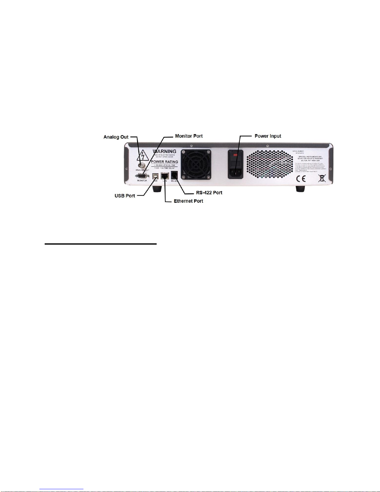
Power Supply Connections...................................................................................................7
Signal Output Connections ...................................................................................................8
Software Installation..............................................................................................................9
3LASER INPUT....................................................................................................................10
Fiber-Optic Laser Input .......................................................................................................10
Free-Beam Laser Input.......................................................................................................11
4USING THE LASER WAVELENGTH METER ....................................................................13
Operation Instructions.........................................................................................................13
Wavelength Screen ............................................................................................................14
Trend Screen......................................................................................................................15
PID Controller Screen.........................................................................................................17
Menu Function Descriptions................................................................................................19
5MAKING MEASUREMENTS..............................................................................................31
System Calibration..............................................................................................................31
Setting Measurement Rate .................................................................................................31
External Trigger..................................................................................................................32
High Speed Data Acquisition...............................................................................................34
Stored Data Buffer..............................................................................................................36
6REMOTE COMMUNICATIONS ..........................................................................................38
Web-based Display Application...........................................................................................38
Direct Communication.........................................................................................................41
SCPI Communications Scheme ..........................................................................................43
APPENDIX A –SPECIFICATIONS...........................................................................................62
APPENDIX B –WARRANTY & SERVICE................................................................................63
APPENDIX C –RNDIS TROUBLESHOOTING.........................................................................64
Windows 7..........................................................................................................................64
Windows 10........................................................................................................................68
APPENDIX D –INSTRUMENT TROUBLESHOOTING.............................................................72
APPENDIX E –STATUS BYTE DEFINITIONS.........................................................................73
APPENDIX F –FIBER-OPTIC CLEANING INSTRUCTIONS....................................................74
SOFTWARE COPYRIGHT ACKNOWLEDGEMENT.................................................................75
Declaration of Conformity ......................................................................................................76

Model 871A User’s Manual INTRODUCTION
Bristol Instruments, Inc. 4
1 INTRODUCTION
Welcome
Thank you for purchasing the 871 Series Laser Wavelength Meter from Bristol Instruments. The
model 871A measures absolute laser wavelength to an accuracy of ±0.2 parts per million, and is
available for operation over the wavelength ranges of 375 –1100 nm (VIS version) and 630 –
1700 nm (NIR version).
This User’s Manual includes information about the 871A Laser Wavelength Meter. It covers all
the topics necessary to help you operate your system.
If you have any questions about the operation of your 871 system, please do not hesitate to call
Bristol Instruments at (585) 924-2620. Or, you can contact us at service@bristol-inst.com.
Bristol Instruments, Inc.
770 Canning Parkway
Victor, NY 14564
Tel: (585) 924-2620
Fax: (585) 924-2623
service@bristol-inst.com
www.bristol-inst.com
Safety Notices
Warning denotes a hazard. It calls attention to a procedure that, if not correctly performed or
adhered to, could result in injury or loss of life. Do not proceed beyond a warning sign until the
indicated conditions are fully understood and met.
Caution denotes a hazard. It calls attention to a procedure that, if not correctly performed or
adhered to, could result in damage to or destruction of the product. Do not proceed beyond a
caution sign until the indicated conditions are fully understood and met.

Model 871A User’s Manual INTRODUCTION
Bristol Instruments, Inc. 5
General Safety Considerations
This product has been designed and tested in accordance with IEC 61010-1 and has
been supplied in a safe condition. The instruction documentation contains information
and warnings that must be followed by the user to ensure safe operation and to maintain
the product in a safe condition.
Laser Classification: This product is classified FDA Laser Class I (IEC Laser Class 1).
If this instrument is not used as specified, the protection provided by the
equipment could be impaired. This instrument must be used in the specified mode
without deviation from the written instructions. Use of this product in any manner
other than described herein may cause permanent damage to eyesight and
therefore is strictly prohibited.
Never inspect or clean a fiber-optic cable without first disconnecting the entire
cable assembly from the optical source. Failure to take this precaution can
permanently damage your eyesight.
No user serviceable parts are inside. Refer servicing to Bristol Instruments or its
representatives only. To prevent electrical shock, do not remove covers.
To prevent electrical shock, disconnect this instrument from mains before
cleaning. Use a dry cloth or one slightly dampened with water to clean the
external case parts. Do not attempt to clean internally.
This is a Safety Class 1 product (provided with protective ground). The mains plug
shall only be inserted in a socket outlet provided with a protective ground contact.
Any interruption of the protective conductor inside or outside of the product is
likely to make the product dangerous. Intentional interruption is prohibited.

Model 871A User’s Manual INTRODUCTION
Bristol Instruments, Inc. 6
Always use the three-prong AC power cord supplied with this instrument. Failure to
ensure adequate grounding by not using this cord may cause instrument damage.
Do not connect AC power until you have verified the line voltage is properly grounded
and within the specified range (90–260 VAC and 47–63 Hz). Damage to the instrument
could result.
This instrument has autoranging line voltage input. Be sure the supply voltage is within
the specified range.
Maximum safe input is 10 mW of CW or time-averaged optical power, or 0.5 mJ of pulsed
laser energy (10 ns pulse). Laser input power in excess of these values can result in
damage to the instrument.
Use care in handling fiber-optic connectors. Always clean the fiber end prior to insertion
into the instrument’s fiber-optic connector for optimum performance. Failure to do so can
result in damage to the instrument.
Inspection
The 871 Series Laser Wavelength Meter is packed in a carton designed to give maximum
protection during shipment. If the outside of the shipping carton is damaged, notify your
shipping department immediately. Your shipping department may want to notify the
carrier.
If the shipping carton is not damaged, carefully remove and identify all of the components
listed below. Contact Bristol Instruments or your local representative if any of the
components are missing. We recommend that you save the shipping carton for future
storage or transportation.
The 871 system includes the following components:
Laser Wavelength Meter
Power cord (North America and Japan only)
USB 2.0 cable
RS-422 to USB converter cable
Trigger cable
USB flash-drive with NuView software and User’s Manual
Fiber-optic cleaning kit

Model 871A User’s Manual INITIAL INSTRUMENT SETUP
Bristol Instruments, Inc. 7
2 INITIAL INSTRUMENT SETUP
General
1 Place the 871 Laser Wavelength Meter on a firm horizontal surface.
2 Make sure that there is at least 2 inches (50 mm) of clearance on all sides of the
instrument to allow for ventilation.
Power Supply Connections
This is a Safety Class 1 product (provided with protective ground). The mains plug
shall only be inserted in a socket outlet provided with a protective ground contact.
Any interruption of the protective conductor inside or outside of the product is
likely to make the product dangerous. Intentional interruption is prohibited.
Always use the three-prong AC power cord supplied with this instrument. Failure to
ensure adequate grounding by not using this cord may cause instrument damage.
Do not connect AC power until you have verified the line voltage is properly grounded
and within the specified range (90–260 VAC and 47–63 Hz). Damage to the instrument
could result.
This instrument has autoranging line voltage input. Be sure the supply voltage is within
the specified range.

Model 871A User’s Manual INITIAL INSTRUMENT SETUP
Bristol Instruments, Inc. 8
1Verify that the line power meets the requirements shown below.
•95 to 260 VAC
•47 to 63 Hz
•Protective Ground
2Connect the line-power cord to the power input connector on the instrument’s back
panel (Figure 2.1).
3 Connect the other end of the line-power cord to the power receptacle.
Figure 2.1: Back Panel
Signal Output Connections
The 871 Laser Wavelength Meter has the following connections for signal output and
communications. These connections are located on the instrument’s back panel
(Figure 2.1).
•USB Port - Interface to a PC for instrument control and data reporting.
•Ethernet Port –Interface to a PC for instrument control and data reporting.
•RS-422 –Interface to a PC for real-time data reporting.
•DB-9 Monitor Port - Used to trigger measurements and view measurement
timing. A full description of the external trigger and the measurement timing is
provided in Chapter 5.
•Analog Out –Used to supply voltage for stabilizing a laser source. A full
description of the Analog Out and the PID Control function is described in
Chapter 4.
1Connect the USB interface cable to the USB port on the back panel of the instrument.
2Connect the other end of the USB cable to a USB port on your PC.

Model 871A User’s Manual INITIAL INSTRUMENT SETUP
Bristol Instruments, Inc. 9
Software Installation
The NuView software, provided on the Application Software flash drive, controls the 871
Laser Wavelength Meter and displays the collected data. The following computer
hardware is required to run the software.
•A PC running Microsoft Windows 7, 8 or 10
•At least 1 GB of available RAM
•USB 2.0 (or later), Ethernet port for instrument connection, or a wired or wireless
network connection (to connect to the instrument over the network)
•Monitor
•Mouse or other pointing device
1 Insert the Application Software flash drive into a USB port on your PC. Double click
on the NuView software installer to begin.
2 Once the software is installed, a shortcut to the NuView software will automatically be
placed on the Start Menu (or Application Menu) of the PC. Click on this icon to open
the application.
3 Navigate to the “Help” menu and select “Model 871A User’s Manual” to download a
PDF file of the 871A system’s User’s Manual (this file) from Bristol Instruments’
website. This User’s Manual will describe installation and operation of the 871A
system. A copy of this manual is also included on the Application Software flash
drive.
4 The USB connection to the PC uses a RNDIS driver for a virtual Ethernet connection.
The RNDIS driver is included with every Windows PC, but Windows 7 typically does
not have this driver activated. Windows 8 and 10 will activate the driver when a
RNDIS device is connected, but occasionally Windows 10 will incorrectly recognize a
RNDIS device as a COM port. For further troubleshooting regarding RNDIS, please
see Appendix C.

Model 871A User’s Manual LASER INPUT
Bristol Instruments, Inc. 10
3 LASER INPUT
Fiber-Optic Laser Input
Never inspect or clean a fiber-optic cable without first disconnecting the entire
cable assembly from the optical source. Failure to take this precaution can
permanently damage your eyesight.
Use care in handling fiber-optic connectors. Always clean the fiber end prior to insertion
into the instrument’s fiber-optic connector for optimum performance. Failure to do so can
result in damage to the instrument.
Maximum safe input is 10 mW of CW or time-averaged optical power, or 0.5 mJ of pulsed
laser energy (10 ns pulse). Laser input power in excess of these values can result in
damage to the instrument.
The laser under test enters the 871 system through an FC/PC fiber-optic connector on
the front panel of the instrument (Figure 3.1). To achieve the highest accuracy of ± 0.2
parts per million, the input fiber must be single mode at the operational wavelength.
Figure 3.1: Front Panel of the 871 System

Model 871A User’s Manual LASER INPUT
Bristol Instruments, Inc. 11
1 Ensure that all fiber-optic connectors are clean and dry. The 871 system is shipped
with a fiber cleaning kit consisting of a package of connector cleaning sticks, clean
wipes, and fiber-optic splice & connector cleaner spray. See Appendix F for cleaning
instructions.
2 Connect your fiber-optic patchcord to the pre-aligned FC/PC fiber-optic connector on
the instrument’s front panel. Make certain that the alignment key on the fiber-optic
patchcord’s connector (Figure 3.2) is properly seated in the slot of the input
connector.
Figure 3.2: Basic Components of an FC/PC Fiber-Optic Connector
3 Tighten the mechanical retainer with a light to medium finger-tightness. Exceeding
this torque may result in a poor connection or may damage the connector.
Free-Beam Laser Input
Never inspect or clean a fiber-optic cable without first disconnecting the entire
cable assembly from the optical source. Failure to take this precaution can
permanently damage your eyesight.
Use care in handling fiber-optic connectors. Always clean the fiber end prior to insertion
into the instrument’s fiber-optic connector for optimum performance. Failure to do so can
result in damage to the instrument.
Maximum safe input for the 871 Series Laser Wavelength Meter is 10 mW of CW or time-
averaged optical power, or 0.5 mJ of pulsed laser energy (10 ns pulse). Laser input
power in excess of these values can result in damage to the instrument.
Maximum safe input for the BC-1 Series is limited by the fiber-optic patch cord connected
to the BC-1. Refer to the maximum optical power and laser energy specifications
provided by the fiber-optic patch cord manufacturer.

Model 871A User’s Manual LASER INPUT
Bristol Instruments, Inc. 12
If the laser under test has a free space beam, it must be launched into a fiber-optic
patchcord for entry into the 871 Laser Wavelength Meter. The BC-1 Fiber-Optic Input
Coupler offered by Bristol Instruments is a convenient method of doing this.
(1) Install the BC-1 coupler in any two-axis (Θ-Φ) adjustable optical mount that can
accommodate a 1 inch (25.4 mm) diameter optic. Optical mounts with X–Y
translational adjustment may be convenient in some laboratory configurations.
(2) Center the laser beam on the 2.5 mm input aperture of the BC-1 coupler. Using the
angular adjustments of the optical mount, adjust the face of the beam coupler to be
orthogonal to the laser beam.
(3) Two back reflections from the BC-1 coupler should be visible near the laser’s output
aperture. They can also be seen by placing a white card (with a hole in the center) in
the beam path as shown in Figure 3.3. Adjust the optical mount until the reflections
symmetrically straddle the input beam.
Figure 3.3: Aligning the BC-1 Fiber-Optic Input Coupler
(4) Maximize throughput, using visual or power meter detection, by making minor
angular adjustments with the Θ-Φoptical mount.
Theta - Phi
Optical Mount
BC-1 Fiber-Optic
Coupler
Back
Reflection
Laser
Source
Back
Reflection

Model 871A User’s Manual USING THE LASER WAVELENGTH METER
Bristol Instruments, Inc. 13
4 USING THE LASER WAVELENGTH METER
Operation Instructions
1 Turn on the power switch of the 871 Laser Wavelength Meter located on the front
panel of the instrument.
2 Make sure the supplied USB cable is connected to the USB connector on the back
panel of the 871 system and to a USB port on the PC.
3 Start the NuView software by clicking on its icon. The NuView software will display
the Bristol Instruments logo before any instrument is connected (Figure 4.1)
Figure 4.1: Start-Up Screen
4 Open the Instrument Menu and select Connect.
5 Select “Model 871” from the drop down list.
6 Make sure that the “Connect via USB” radio button is selected, then click Connect.
The status text at the bottom-left corner of the screen should change to “Connected.”
If an error message is displayed instead, double-check that the instrument is running
and connected as described in Steps 1-2.

Model 871A User’s Manual USING THE LASER WAVELENGTH METER
Bristol Instruments, Inc. 14
Wavelength Screen
The Wavelength Screen of the NuView software displays the absolute wavelength,
wavenumber, or frequency of the laser under test. Once the application is connected to
the instrument, the Wavelength display will update continuously until the connection is
terminated.
Figure 4.2: Wavelength Screen
Wavelength/Trend/PID Controller Tabs
Allows the user to toggle between the Wavelength Screen, Trend Screen, and
PID Controller Screen.
Wavelength Display
Displays the absolute wavelength, wavenumber, or frequency of the laser under
test.
Intensity Meter
Graphically displays the relative intensity of the laser under test on the
instrument’s detector.
Status Bar
The Status bar is located at the bottom of the Wavelength Screen and the Trend
Screen. It provides information about the current state of the instrument as
described below (from left to right).
•Connection status –Either connected or disconnected.
•Trigger Method –Either Internal (INT), External Falling (EXT Fall), or
External Rising (EXT Rise).
•Frame Rate –The detector’s frame rate in Hz.
•Averaging –Either “Off” or the number of samples being averaged.
•Logging –The downloading icon is gray when logging status is inactive, and
green when logging status is active.
Figure 4.3: Status Bar

Model 871A User’s Manual USING THE LASER WAVELENGTH METER
Bristol Instruments, Inc. 15
Trend Screen
Figure 4.4: Trend Screen
Measure/Pause
Selecting the Measure button (left) initiates data collection. After the Measure
button is selected, it changes its appearance to the Pause button (middle). The
Trend Graph and Data Table are updated continuously until the Pause button is
selected. Selecting the Pause button stops data collection, and the Trend Graph
and Data Table display the last measured data. When the instrument is not
connected, the Measure button changes its appearance to its greyed-out inactive
state (right).
Clear Selecting the Clear button (left) restarts the Trend Graph and resets the values in
the Data Table. When the instrument is not connected, before any trending data
is collected, or after the trending data has been cleared, the Clear button
changes its appearance to its greyed-out inactive state (right).

Model 871A User’s Manual USING THE LASER WAVELENGTH METER
Bristol Instruments, Inc. 16
Data Table
The Data Table provides current and trending information about the laser’s
wavelength, wavenumber, or frequency.
The first column of the Data Table provides laser drift information. This column
displays the current measurement (Current), the first measurement taken after
the Trend Graph is started/reset (Start), and the difference between the Current
and Start measurements (Drift).
The second column provides the total measured variation of the laser under test.
This column displays the maximum and minimum measurements recorded on
the Trend Graph (Maximum and Minimum, respectively), and computes the
difference between them (Variation).
The third column provides some basic statistical information about the variation
of the Trend Graph. This column provides the average (Mean) and standard
deviation (Std Dev) of the Trend Graph.
Trend Graph Zoom
The Trend Graph can be magnified to focus on a portion of the trending data.
Before zooming, left-click on the Trend Graph to ensure that the Trend Graph is
active, and uncheck “Autoscale Axes” under the View Menu.
•Horizontal Zooming –Scrolling the mouse wheel upwards will zoom in
horizontally on the spectrum at the mouse cursor location. Scrolling the
mouse wheel downwards will zoom out horizontally on the spectrum at the
mouse cursor location.
•Vertical Zooming –Holding the shift key on user’s keyboard while scrolling
the mouse wheel upwards will zoom in vertically on the Trend Graph at the
mouse cursor location. Holding down the shift key while scrolling the mouse
wheel downwards will zoom out vertically on the Trend Graph at the mouse
cursor location.
Trend Graph Panning
When the Trend Graph is zoomed, left-clicking and dragging in the Trend Graph
will pan the trending data horizontally. Holding down the Shift key while left-
clicking and dragging will pan the trending data vertically.

Model 871A User’s Manual USING THE LASER WAVELENGTH METER
Bristol Instruments, Inc. 17
PID Controller Screen
Figure 4.5: PID Controller Screen
The PID Controller Screen displays the settings for the 871-system’s internal PID
controller and reports the most recent wavelength reading and output voltage supplied
through the Analog Out BNC connector on the back panel of the wavelength meter
(Figure 2.1).
The calculation behind the PID Controller Screen consists of three separate voltage
parameters input by the user. The first parameter, Kp, accounts for the current
(Proportional) error magnitude and has the highest contribution to guiding the measured
wavelength towards the set point. The second parameter, Ki, accounts for the sum of
past errors (Integral) to minimize the effects of outlying data peaks or spikes on the
correction voltage. The third parameter, Kd, factors in the current rate of change
(Derivative) to avoid oscillation about the desired wavelength. These three components
ensure swift correction of the laser to the desired frequency with minimal overshooting or
oscillation.
Measure/Pause
Enables the PID calculations to determine the output voltage. Selecting the
Measure button (left) initiates the PID calculation. After the Measure button is
selected, it changes its appearance to the Pause button (middle). The PID
calculation updates continuously until the Pause button is selected. Selecting the
Pause button stops data collection. When the instrument is not connected, the
Measure button changes its appearance to its greyed-out inactive state (right).

Model 871A User’s Manual USING THE LASER WAVELENGTH METER
Bristol Instruments, Inc. 18
Wavelength Display
The most recent wavelength measurement.
Error Display
The difference between the target wavelength and the Wavelength Display.
Output Display
The current voltage output being delivered through the BNC connector on the
back panel of the 871 instrument.
Data Table
Allows entry of the PID parameters, default output voltage, and voltage offset
values. Click on any field to change the value and type the desired value in using
the keyboard. Click Save Instrument Settings from the Instrument menu to
commit these changes to the PID calculation.
•Set Point –The target wavelength, frequency, or wavenumber for the PID
calculation.
•Offset –An additional voltage offset added to the PID computed voltage.
This is useful for centering the voltage output swing at a value other than
zero.
•Scale –Multiplier for converting the error signal into a voltage, expressed in
volts per nanometer. Even when multiplied by the Scale the output voltage
remains capped by the instrument limits of ± 5 volts or the user defined
maximum and minimum voltages.
•Kp–Proportional gain constant. The Proportional gain constant is unit-less,
and has the highest contribution to guiding the measured wavelength
towards the desired frequency.
•Ki–Integral gain constant. The Integral gain constant, expressed in Hz,
accounts for the sum of past errors to minimize the effects of outlying data
peaks or spikes on the output voltage.
•Kd–Derivative gain constant. The Derivative gain constant, expressed in
seconds, factors in the current rate of change to avoid oscillation about the
desired wavelength.
•Minimum Voltage –The lower limit, expressed in volts, for the output
voltage. This voltage is automatically limited by the instrument to - 5 volts.
•Maximum Voltage –The upper limit, expressed in volts, for the output
voltage. This voltage is automatically limited by the instrument to + 5 volts.
•Default Output –The voltage output when the PID calculation is paused.
The Default Output is expressed in volts, and must be within the instrument
limits of ± 5 volts.

Model 871A User’s Manual USING THE LASER WAVELENGTH METER
Bristol Instruments, Inc. 19
Menu Function Descriptions
File Menu
•Start Data Logging –The wavelength measurements can be logged in a
Comma-Separated Value (*.csv) file format for use in other graphing
programs. If “Stop after..measurements” or “Stop after…hours, minutes,
seconds” are selected, logging will stop automatically after the specified
number of measurements or amount of time, respectively. If “Stop manually”
is selected, then logging must be stopped manually by clicking the Stop Data
Logging menu item. The default file name is “NuView log 1.csv.” If you use
this filename, the number at the end will increment each time you begin a
new log.
Each measurement can be logged, or measurements can be recorded at a
measurement or time interval.
The columns of the CSV file are defined by the available measurement
parameters listed below. The first column of the log file is a timestamp for
each measurement, followed by the selected parameters. Click the check
box next to a parameter to include that column in the CSV file.
- Instrument Status –A hexadecimal number corresponding to the
instrument status at each measurement. The status numbers are defined
in Appendix E.
- Max Peak Wavelength –The absolute wavelength, wavenumber, or
frequency of the laser under test.
- Max Peak Intensity –A linear value representing the illumination of the
detector array. This value ranges from 0 (no light) to 1 (fully saturated
detector).
Click on Start Data Logging, then change the log file name and location or
use the default name and location. Select the radio button for the logging
type. When “Stop after…measurements” is selected, the number of
measurements can be adjusted incrementally using the up/down arrows or
by highlighting the current numeric value and entering a new numeric value
with the keyboard. When “Stop after…hours, minutes, seconds” is selected,
the time can be adjusted incrementally using the up/down arrows or by
highlighting the current time duration and entering a new time duration with
the keyboard.

Model 871A User’s Manual USING THE LASER WAVELENGTH METER
Bristol Instruments, Inc. 20
Select the radio button for the Logging Interval. When “Measurement” is
selected, the number of measurements can be adjusted incrementally using
the up/down arrows or by highlighting the current measurement interval and
entering a new measurement interval with the keyboard. When “Time” is
selected, the time can be adjusted incrementally using the up/down arrows or
by highlighting the current time duration and entering a new time interval with
the keyboard. Check the boxes next to each measurement parameter you
wish to track. Click Start to begin the logging of wavelength data.
•Stop Data Logging –Stops the current logging operation. Note that if you
started logging using the “Stop after measurements” or “Stop after hours,
minutes, seconds” options, logging will stop automatically and you do not need to
click on Stop Data Logging unless you wish to abort early. In either case, the
logging data will be written to the specified file when data logging is stopped.
•Load Settings –Opens a previously saved Settings file from a text-based
initialization (*.ini) format file. These files can be used to quickly configure the
NuView software for different users or experimental setups. Click on Load
Settings, browse to find the desired settings file, select it, and click on Open to
load the Settings file.
Table of contents
Other Bristol Measuring Instrument manuals
Popular Measuring Instrument manuals by other brands

PCB Piezotronics
PCB Piezotronics M1403-03ADB Installation and operating manual

Vitrek
Vitrek 951i operating & maintenance manual

Ametek
Ametek 5100 HD user manual

Badger Meter
Badger Meter FC-5000 user manual

SubSurface Instruments
SubSurface Instruments LC-5000 Simple operation manual

Instantel
Instantel 716A0401 Operator's manual

Polatrak
Polatrak CP-Gun Operation manual

Triplett
Triplett CM1050 user manual

Kingwell
Kingwell 600 Series Instructions for use

SICK
SICK VMS6200 operating instructions

Endress+Hauser
Endress+Hauser Master Meter System operating instructions

PCB Piezotronics
PCB Piezotronics J352B/ACS-23 Installation and operating manual