Britannia BTH-C-950 Owner's manual

1. INTRODUCTION
Your range cooker is a semi-professional unit which gives you the power
and flexibility to realise your full potential in the kitchen. Inevitably, during
the cooking process, there will be heat, vapours and fumes produced.
Your Latour extractor has been designed to complement the range cooker
both in looks and performance in order to create the ideal environment for
creative cooking.
2. EXTRACTION PERFORMANCE
The most important influence on the performance of the extractor is the
design of the ducting which takes the exhaust air from the extractor to
the outside wall louvre. The duct route should be a prime consideration
during the initial stages of the kitchen design. Please note the following:
This hood is designed for ducting out, i.e. duct to an outside wall.
The extractor is provided with a spigot suitable for connecting
150mm diameter duct. Twin (2000 m3/hr versions) have two
blower assemblies complete with two separate exhaust spigots
for independent ducting to the outside.
Note: 150mm is the minimum duct diameter consistent with efficient
extraction.
The exhaust duct route length should be kept as short as possible
with as few bends as possible.
The most efficient configuration is to duct straight through an outside
wall so try to position the cooker against an outside wall when
designing your kitchen layout.
Rigid 150mm round ducting or an equivalent flat channel system will
perform best, with semi-rigid being the second best solution. Flexible
ducting is economical but it’s use should be minimised as it gives the
worst performance and should only be used for short duct runs or
initial connection and be pulled taut to prevent significant losses in
extraction efficiency. See section 6: Additional Ducting Information
A route with more than two 90obends will significantly degrade the
performance of the extraction system. If possible, avoid having a 90o
bend at the extractor exhaust spigot; keep bend radii as large as
possible to maintain a smooth airflow without vortices; avoid kinks in
flexible ducting; pull flexible ducting taut over straight runs to ensure
that the internal surface is as smooth as possible.
Duct runs in excess of 5 metres are not recommended and will
seriously impair efficiency - if you are concerned then please call for
advice.
Please also note that a 90obend in the flexible or semi rigid ducting
will require 215mm minimum headroom to give a smooth radius with
no kinking.
3. IMPORTANT INFORMATION
Compliance with the following notices will ensure that the installed
product is safely installed and is safe to use.
The minimum distance between the hob and the bottom of the
extractor is essential to prevent overheating of the extractor and its
components.
The exhaust air must not be discharged into a flue which is used for
exhausting fumes from appliances supplied with energy other than
electricity, e.g. oil or gas-fired central heating boilers, gas-fired water
heaters, etc.
Requirements of the relevant authorities concerning the discharge of
exhaust air must be complied with.
Attention: This appliance requires an earth connection.
Ensure that the supply voltage corresponds to that marked on the
rating label inside the extractor.
The extractor must be isolated from the electrical supply before
carrying out any cleaning or maintenance operations.
Pay particular attention to fire risk when frying. To minimise the
risk of fire, all instructions relating to cleaning the grease filters
and removing grease deposits must be adhered to.
Do not flambé under the extractor.
See Section 7 for PRODUCT GUARANTEE information.
4. INSTALLATION
Do not throw away the box and any internal packaging until
installation is fully completed - the packaging may be required in the
unlikely event that hood must be returned.
The Latour Canopy range of built in hoods are designed to slot into an
opening made in a horizontal soffit panel - usually the underside of
kitchen furniture, timber canopies or false/real chimney breasts.
4.1. Prepare Opening
The soffit panel into which the unit is to be fixed must be between
15mm and 22mm thick.
Prepare an opening where the extractor is to be installed. Opening
and Extractor dimensions are shown in Section 8: Latour Canopy
General Arrangement Drawings.
4.2. Duct Installation
Make holes, as necessary, in the walls or ceiling to take the 150mm
diameter ducting from the extractor exhaust spigot to the outside. If
your extractor has twin spigots you will require two separate duct
runs to the outside
The exhaust duct route length should be kept as short as possible
with as few bends as possible - see Section 2.
If terminating on an outside wall a suitable weather louvre, designed
for connection to 150mm ducting or larger, should be fitted - an
airbrick must never be used. A variety of ducting components and
complete kits are available. See Section 6: Additional Ducting
Information.
For roof or chimney duct terminations please contact your supplier
or seek alternative specialist advice.
Recirculating Models Only
We do not recommend recirculating air installations and they should
be avoided wherever possible (see section 2).
For recirculating installations you must allow for the exhaust air to
blow back into the kitchen (or an adjacent room - e.g. utility room).
Open topped furniture or ducting to a vent back into the room are
common ways of achieving this as the air leaving the extractor
spigot must have somewhere to go.
Any ducting or openings used for return air must be at least
equivalent in cross sectional area to that of 125mm diameter duct
otherwise the unit may overheat and fail and you will invalidate your
warranty.
Additional ducting information and components can be found
in Section 6
Cooker-to-canopy clearance (minimum):
Recommended clearance range: 700 mm
750 - 850 mm
Canopy height (excluding Duct Spigot): 280 mm
Warning
The following is a requirement of UK and European legislation
and is in the interests of your safety.
If the room where the cooker hood is to be used contains a fossil fuel
burning appliance such as a gas or oil central heating boiler, then its
flue must be of the room sealed or balanced flue type. A ducted hood
is not suitable for use in a room where any open flue is in use, as
dangerous fumes of combustion can be sucked back in to the room.
This would include the following open flue appliances –central
heating boilers, coal fires, log fires, gas fires, wood burning stoves
etc. Therefore, if you have an open flue fossil fuel burning appliance
in your kitchen, you are automatically compelled to select a hood that
is capable of working in recycling mode.
BTH-C-950
BTH-C-1150
BTH-C-1400
BTH-CT-950
BTH-CT-1150
BTH-CT-1400
Latour Canopy Hood
Installation, Operation
& Maintenance
Instructions
id1080182015 pdfMachine by Broadgun Software - a great PDF writer! - a great PDF creator! - http://www.pdfmachine.com http://www.broadgun.com

Latour Canopy Hood Installation, Operating & Maintenance Instructions
W1100 Latour Built-In Canopy Extractor IO&M Nov 2010.docx Page 2
4.3. Electrical Installation
The extractor is a stationary appliance designed to be connected
by fixed wiring to the electrical supply. A competent electrical
technician must perform the electrical installation.
The extractor must be fed from a 220-240Vac single phase
electrical supply using a switched spur fitted with a 3A fuse. The
spur should be located such that the supply can be disconnected
from the hood using the switch after installation (adjacent to the
hood or cooker or cooker is best). The means of disconnecting
from the supply must have a minimum contact separation of 3mm
in all poles. Alternatively a means of disconnection in the fixed
wiring according to the relevant wiring regulations must be fitted.
A supply cord for connecting the extractor to the spur is included.
The mains supply is connected to the free end of this cord as
follows:
Core Live Neutral Protective Earth
Core Colour Brown Blue Green/Yellow
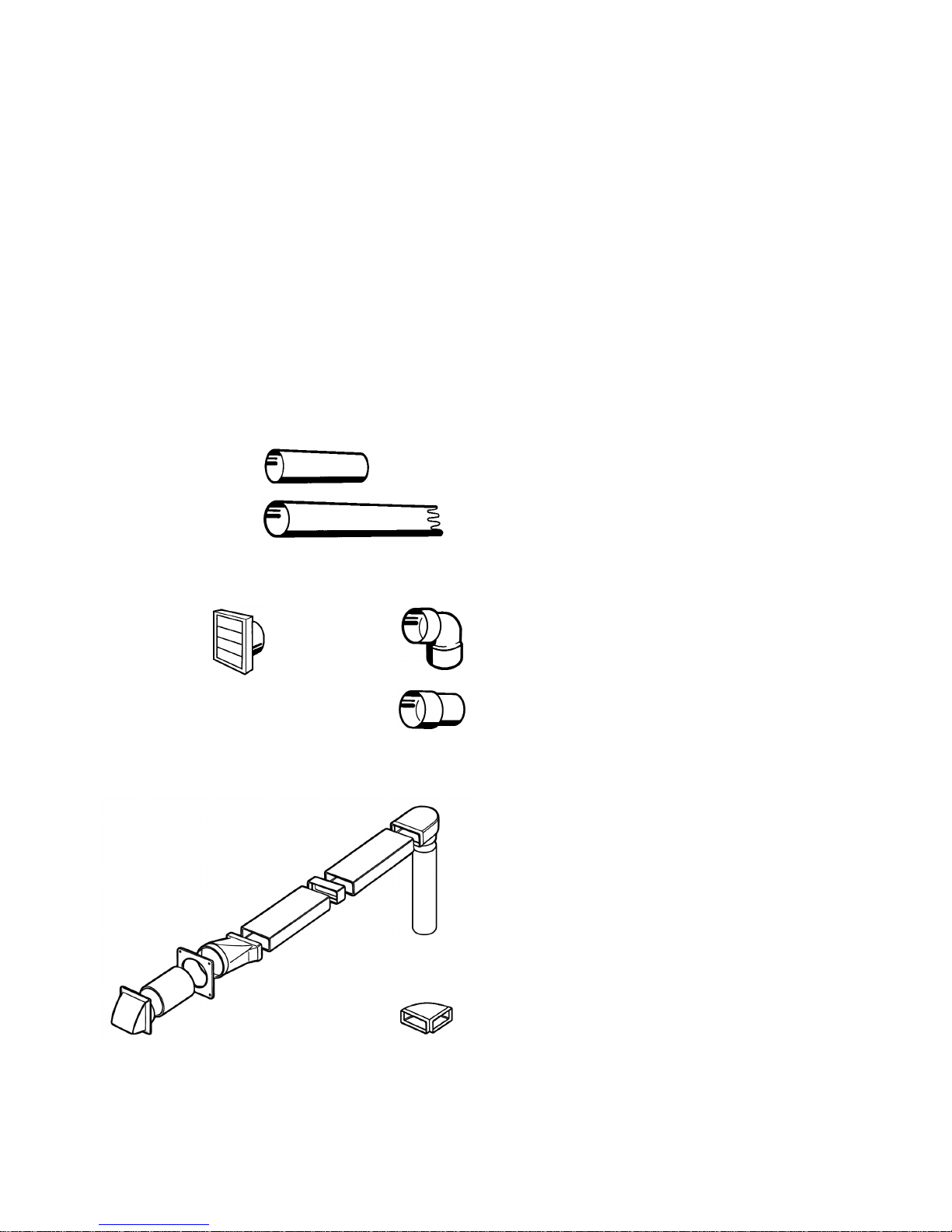
4.4. Connecting the Ducting
Terminate the ducting where it exits the building. If using a wall
mount weather louvre secure the ducting to the louvre spigot and
attach the louvre to the wall. Ensure that the air fins are directed
downwards. If you are fitting an alternative termination ensure that
the ducting is secure.
If using expanding foam make sure that any flexible ducting is
supported internally to prevent it crushing or use rigid ducting
through the wall where foamed.
Pull any flexible ducting back along its route such that it is as
smooth as possible. Position the extractor face down and as close
to the opening as is practical and cut off excess before connecting
the ducting to the extractor exhaust spigot(s) using plastic tie
straps or a suitable alternative (e.g. jubilee clip).
Secure the louvre to the outside wall. Ensure that any air fins are
directed downwards.
Check that the duct has not been flattened or kinked.
4.5. Fixing the Extractor in position.
Fixing the extractor safely into position requires two people so do not start
if assistance is unavailable.
Remove the grease filters as described in Section 10.
The extractor is held securely in place by 4 adjustable spring
toggles (only visible on the outer casing of the unit).
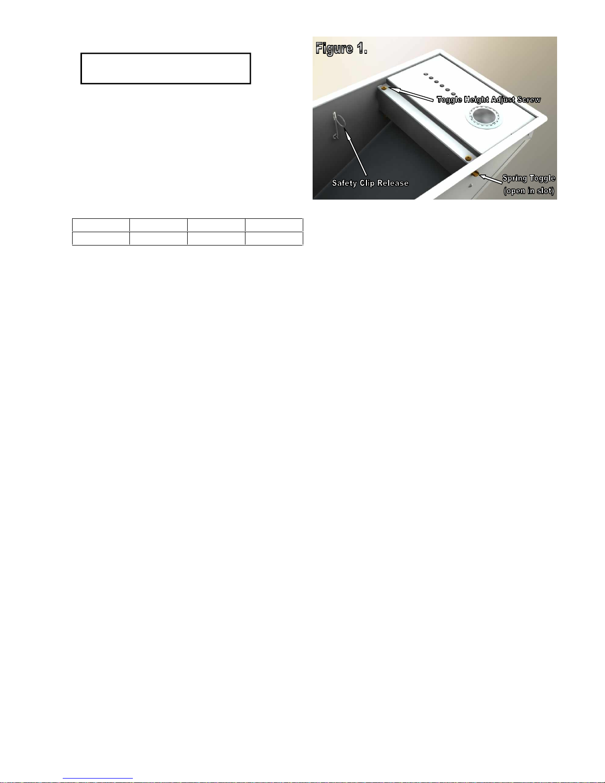
Screws for adjusting the height of each spring toggle are located
behind the grease filters on the outer filter housing flange (see
Figure 1). The spring toggles are moved up by turning the screws
anti-clockwise and down by turning clockwise.
Ensure that each spring toggle height is set such that when pushed
from outside it moves freely and fully into the outer casing of the
unit and when slowly released returns to an open position just
below the top of the spring toggle slot. The spring toggle should
protrude from the casing by at least 8mm (see Figure 1).
Suplementary support of the unit is provided by sprung safety clips
which are intended to hold the unit safely in place during removal
(see later). The safety clips (See Figure 1) should be disabled for
installation by pulling the clip release into the body until the clip
latch is clear of it’s slot and then sliding to one side so that the clip
latch rests against the inner casing of the unit.
Check that the electrical supply chord has been connected, that
power is switched off and that the ducting is securely fastened to
the spigot. Check, if applicable, that any external fans are plugged
into the unit.
Push the extractor up through the prepared opening until the spring
toggles are heard to snap over the edge of the opening –we
recommend that two people do this supporting one end of the
extractor each. Carefully release the unit ensuring that it is
supported within the opening by all four spring toggles. If a spring
toggle fails to catch try pushing upwards again and if this fails
remove the unit as described later and check the panel thickness
and setting of the spring toggles as described earlier.
Re-enable the two sprung safety clips by once again pulling the
safety clip release (Figure 1.) and sliding the clip latch back into the
slot from which it was earlier withdrawn. The clip latch should pass
fully through the outer casing.
Close up any gaps between the soffit panel and the units outer
flange (often referred to as the fixing flange) by turning the spring
toggle adjustment screws clockwise. If the gap is larger that 1-2mm
then this should be done in stages of approximately 1mm, working
your way around each of the four adjustment screws in turn until the
unit has been pulled up into position.
Note: Ideally, although not always possible, access to the ducting
should be provided for when the unit is in place, for straightening
the duct following installation, inspection and future repair work.
5. REMOVING THE CANOPY HOOD
First remove the grease filters and ensure that the sprung safety
clip is correctly set. Only the clip release grip and mounting arm
should be on the inside of the unit (as in Figure 1) with the latch fully
through the slot in the hood casing. If in doubt pull the clip release
to reveal the clip latch and make sure that it passes fully back
through the casing when released.
With the safety clips correctly set turn the spring toggle adjustment
screws anti-clockwise. The extractor will gradually start to lower.
This is best done in stages, working your way around the 4 screws
thus lowering the unit evenly and avoiding undue stress on any one
spring toggle. Note: as you turn the adjustment screws the spring
toggles gradually rise until they reach the top of their slots after
which they start to retract into the hood casing.
You will know when the spring toggles start to retract because the
hood will start to rise up slightly into the soffit rather than lower.
When this happens you should support the extractor and continue
to turn the screws carefully clockwise. When the spring toggles
have retracted sufficently the unit will lower once again - this will
happen suddenly if you are not supporting the hood.
The sprung safety clips are there to catch the unit and to prevent it
falling from the opening in the soffit should you let go of the hood. If
you do need to let go of the hood then do so carefully, ensuring that
the safety clips have indeed trapped the unit in the opening before
letting go of the hood. This is a supplementary support system
intended to lessen the risk of dropping the unit and, when correctly
engaged, to provide momentary support.
Two people are required to lower the unit safely. The unit is
released for final lowering by each person pulling the safety clip
release into the body whilst supporting the unit with their other
hand. When the clips are pulled into the body the spring latch will
disengage from the soffit and the unit can be lowered.
ELECTRICAL HAZARD
DISCONNECT ELECTRICAL SUPPLY
BEFORE PROCEEDING FURTHER

Latour Canopy Hood Installation, Operating & Maintenance Instructions
W1100 Latour Built-In Canopy Extractor IO&M Nov 2010.docx Page 3
6. ADDITIONAL DUCTING INFORMATION
This hood is designed for ducting out, i.e. duct to an outside wall. To
obtain the best possible extraction performance use 150mm
diameter ducting. Wherever possible utilise rigid circular pipe or
“Mega duct”ducting - both types are available via your Britannia
dealer. Do not use flexible expanding concertina type ducting
unless it is absolutely necessary and then only for short runs (of
less than 1 metre) or initial connection as this is not smooth on the
interior and will cause air flow restrictions.
Do not use ducting that has a smaller diameter than 150mm as this
will reduce extraction rates and can increase noise levels. Please
note ducting kits and ducting components are optional accessories
and have to be ordered - they are not supplied with the hood.
Recommended maximum length of ducting run.
4 metres with 1 x 90 degree bend
3 metres with 2 x 90 degree bends
2 metres with 3 x 90 degree bends
Note: The shorter the ducting run and the least number of bends
gives the best extraction performance.
Warning:Any ducting used must be fire retardant.
7. PRODUCT GUARANTEE
Britannia service & spare department
Tel: +44 (0)844 463 9705 (option 1)
GUARANTEE
What the Guarantee covers
Our service division will repair or replace free of charge
any defect or component that is due to faulty material or
workmanship, provided that such a defect occurs within
2 years of date of purchase and that:
1. Our service division is notified promptly of any defects.
Under the terms of the guarantee the appliance must be
made available for service during normal working hours,
Monday to Friday.
2. The appliance is installed in accordance with these
instructions and for normal domestic use.
3. The guarantee does not apply if the appliance is
repaired or modified by any other person than a member
of our service division. The guarantee does not cover
misuse, improper installation or any installation in
commercial premises. This product is for domestic use
only.
4. Any service work will generally entail removal of the
telescopic flue assembly to access key components
including the motor. If the flue assembly has been boxed
in by means of a bridging shelf or any type of furniture
this must be removed prior to our engineer’s visit.
Before calling for service, please check the following:
1. Is there a power failure? Turn on the appliance to check
the mains supply.
2. Check that the fuse has not blown.
3. Please note that bulbs are not covered under the
guarantee.
In the event of service being required, our service
division will request the following information:
1. Your name, address and postcode.
2. Your telephone numbers for home and work.
3. The model number and colour of the appliance.
4. Precise details of the fault.
5. Date of purchase.
Please note that when the service engineer visits he will
require seeing your proof of purchase date so please retain
your receipt.
1m
1m
35cm
One metre length pipe
Code DUCT/1100-6
Two metre length pipe
Code DUCT/1200-6
Note: One metre and two metre length pipes can be cut to
the desired length.
Wall vent with
gravity flaps
Code DUCT/6900
One metre ducting kit
Comprising: one metre
length pipe, wall vent and
90 degree bend.
Code DUCT/2609
90 degree bend
Code DUCT/690
Pipe connector
Code DUCT/693
Megaduct Ducting Kit
Combination of 6”(150mm)
circular pipe and flat channel
(220mm x 90mm) which is
ideal for running on top of
wall units or between ceiling
joists.
Code DUCT/2652B
Horizontal bend
Code DUCT/950

Latour Canopy Hood Installation, Operating & Maintenance Instructions
W1100 Latour Built-In Canopy Extractor IO&M Nov 2010.docx Page 4
8. LATOUR CANOPY GENERAL ARRANGEMENT DRAWINGS
Single Fan Models
BTH-C-950, BTH-C-1150, BTH-C-1400
Twin Fan Models
BTH-CT-950, BTH-CT-1150, BTH-CT-1400

Latour Canopy Hood Installation, Operating & Maintenance Instructions
W1100 Latour Built-In Canopy Extractor IO&M Nov 2010.docx Page 5
9. OPERATING INSTRUCTIONS
Switch on the power at the fused spur.
The extractor has 6 push-buttons which illuminate when selected.
Their functions are summarised in the table below.
After 30 hours accumulated running GREASE FILTER
SATURATION will be signalled by all 6 indicators flashing. Reset by
pressing Push-button FAN OFF (delay).
The extractor controller will automatically switch off the appliance if
there has been no operator action for 4 hours.
LIGHTS
ON/OFF FAN ON
SPEED 1
FAN OFF
(Immediate)
FAN ON
SPEED 2 FAN ON
SPEED 3 FAN ON
SPEED 4 FAN OFF
Delayed for
10 Minutes
to clear
fumes
10. MAINTENANCE
Regular maintenance is essential to ensure good performance and long-
life.
To clean the stainless steel surfaces of the extractor use a suitable
cleaning agent (Stainless Steel Cleaner and Polish). Glass surfaces
should be cleaned with a suitable glass cleaning agent.
Do not use abrasive cleaning materials or products.
Clean the grease filters in a dishwasher or by hand-washing in hot water
and detergent. Wash the filters at least every 2 months - sooner if the
extractor is used extensively.
To maintain the immaculate appearance of the extractor, and to minimise
fire risk, ensure that grease deposits on the extractor surfaces are kept to
a minimum by regular cleaning.
Removing the Grease Filters
The filters have an integrated sprung latch and release mechanism.
Release the latch by pulling the lever and remove the filter. The filter
is replaced by locating the fixed tabs on the filter into corresponding
slots in the extractor base and then pushing the filter into position with
the latch held open. Once the filter is in position carefully release the
lever, allowing the latch to engage.
Replacing Light Bulbs
The unit is fitted with 20W (20 Watt) 12V (12 Volt Low Voltage) G4
halogen capsule bulbs (lamps). Replacement lamps must be of the
same type (G4 12V 20W).
Never use lamps rated at over 20W.
Remove the frosted glass lens by carefully prising off the lens
retension ring (Figure 2), taking care to support the glass so that it
does not fall. (a fingernail, flat screwdriver, butter knife or similar
can be used to prise off the ring –take care not to scratch the
chrome bezel)
Grasp the lamp and carefully pull it sideways away from and out
of its connection block.
Insert replacement lamp.
Place the frosted lens with smooth face facing downwards (the
face you will see) into retension ring, offer the ring up and align
the ring clips with the corresponding innermost slots in the
chrome bezel and push the ring back into place - this is easiest if
one clip is inserted with the ring at a slight angle (so that you can
see it has located properly) and then pushing up to engage the
remaining two clips.
11. SPECIFICATIONS
Britannia Living
Eastern Rise, Trentham Lakes, StokeonTrent, ST4 8WG
-oOo-
CAUTION
To minimise the risk of fire, all instructions relating to
cleaning the grease filters and removing grease deposits
must be adhered to.
BTH-C-950,1150,1400 with INTERNAL BLOWER
Blower airflow, nominal:
1,000 m3/hr per fan
Noise level:
52dBA Single Fan
56dBA Twin Fan
Supply voltage:
220-240 volts~ 50Hz
Halogen lamp voltage:
12 volts
Blower power input:
250 watts Per Fan
Halogen lamp power:
BTH-C/CT-950:
BTH-C/CT-1150:
BTH-C/CT-1400:
2 x 20 watts
3 x 20 watts
4 x 20 watts
Total power:
Single Fan
Models:
BTH-C-950:
BTH-C-1150:
BTH-C-1400:
290 watts
310 watts
330 watts
Twin Fan
Models:
BTH-C-950:
BTH-C-1150:
BTH-C-1400:
540 watts
560 watts
580 watts
Electrical supply fuse rating:
Single Fan Models:
Twin Fan Models: 3 amp
5 amp
Blower spigot diameter:
150mm
This manual suits for next models
5
Table of contents
Other Britannia Ventilation Hood manuals
Popular Ventilation Hood manuals by other brands

Broan
Broan Rangemaster RM60000 Series Installation instructions and user manual

Indesit
Indesit IHT6.5CMIX Service information

Schweigen
Schweigen UM-12UMS installation guide

CDA
CDA CPXI9 Manual for installation, use and maintenance

Broan
Broan E5490SS manual

Zanussi
Zanussi ZHT 530 Installation, use and maintenance handbook