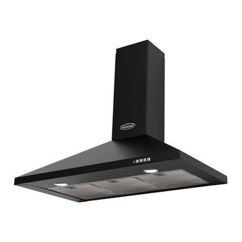
Britannia P780 User manual

USER INSTRUCTIONS
INSTALLATION INSTRUCTIONS
BUILT-IN
CANOPY HOOD
MODEL : P780 - 70CM with ASC
1 of 11

Important safety information
safety information
These warnings are provided in the interests of safety. Ensure that you understand them all
before installing or using this appliance. Your safety is of paramount importance. If you are
unsure about the meaning of any of these warnings please contact the help line above.
Installation
This hood must be installed in accordance with the installation instructions and all measurements
must be adhered to.
A qualified electrician or competent person must undertake any installation work.
If the cooker hood is installed for use above a gas appliance the provision for ventilation must be
in accordance with the latest edition of the Gas Safety Codes of Practice, and the Gas Safety
(Installation & Use) Regulations, the Building Regulations issued by the Department of the
Environment, the Building Standards (Scotland) (Consolidated) Regulations issued by the
Scottish Development Dept.
The fan motor of this cooker hood incorporates a cut -out device, which will operate if the cooker
hood is installed below the minimum height, or if the motor becomes overheated. If the cut-out
device is activated, switch off the fan motor and allow the cooker hood to cool down. The cut-out
device will reset itself when the fan motor has cooled significantly.
It is dangerous to alter the specifications or modify the product in any way.
When installed between adjoining wall cabinets, the wall cabinets must not overhang the
hob/hotplate.
The following applies when ducting outThe following applies when ducting
out
If the room where the cooker hood is to be used contains a fossil fuel burning appliance such as
a gas or oil central heating boiler then its flue must be of the room sealed or balanced flue type.
This hood is not suitable for use in a room where any open flue appliance is in use. There shall
be adequate ventilation of the room when the range hood is used at the same time as
appliances burning gas or other fuels. Any local regulations concerning the discharge of exhaust
air must be checked and fulfilled prior to use of the hood. The ducting system for this appliance
must not be connected to any existing ventilation or flue system that is being used for any other
purpose.
High level grills
Do not install this hood above a cooker with a high level grill.
2 of 11
Britannia Living,
Glen Dimplex Home Appliances,
Eastern Rise, Trentham Lakes,
Stoke-on-Trent
ST4 8WG
Britannia service & spares department
Tel: 0844 463 9705 (Option 1)
Email: service@britannialiving.co.uk

Child safety
This appliance is designed to be operated by adults. Children should not be allowed to tamper
with the appliance.
During use
This product is for domestic use only.
Never leave frying pans unattended during use as overheated fats and oils may catch fire.
Do not flambé foods under the cooker hood
Always turn on your hood every time you use your cooker.
Always use pans with lids.
Do not leave naked flames under the cooker hood.
Maintenance and service
This appliance can be a fire hazard if the grease filters and charcoal filters are not cleaned and
replaced in accordance with instructions.
Always insist on genuine spare parts.
Under no circumstances should you attempt to repair the appliance yourself. Repairs carried out
by inexperienced persons may cause injury or a more serious malfunction.
In the event of service being required for your cooker hood please contact the service helpline.
3 of 11

Technical
SPECIFICATION
Cut-out size
SPEED 1
2
3
4
Air capacity cubic metres
per hour * 340
520
690
750
Pressure PA mm H2O 36
42
45
46
Input Watts 120 150 190 250
Noise level dBA ** 38 48 54 58
* Performance data according to Standard EN61591, Free air delivery.
** Noise level according to Standard IEC60704-2-13
method.
Finish: Stainless Steel
Size: 700mm x 285mm
Cut-out size: 676mm x 261mm
Controls: Electronic
Air outlet: 150mm diameter
Illumination: 2 x halogen lamps 20 watts
Motor: 1 x 250watts (4 speeds)
Total wattage: 290 watts
Mains supply: 230 volts 50 Hz
Connection: via a 13 amp fused spur outlet
fused at 5 amps
Electrical connections
Important: Ensure that the electricity supply is switched off
before connecting.
FUSE RATING: 5 AMP
Your appliance must be connected to fixed wiring via the use of a
double pole switched fused spur outlet with at least 3mm contact
separation. We strongly recommend the appliance is connected by a
qualified electrician who is a member of the N.I.C.E.I.C. or Corgi
who will comply with the I.E.E. and any local regulations.
Note: The terminology “double pole” means that both the live and
neutral supplies are switched and disconnected at the same time.
The terminations labelled SUPPLY are for the internal house wiring
and the terminations labelled LOAD are for connection for the
appliance.
4 of 11
385 440 600 700
35 43 47 48
140 175 210 240
50 60 67 70
285 440 600 700
35 43 47 48
140 175 210 240
50 60 67 70

WARNING - THIS APPLIANCE MUST BE EARTHED
Important: The wires in this mains lead are coloured in accordance with the following code:-
Green/Yellow = Earth, Blue = Neutral, Brown = Live
As the colours of the wires in the mains lead of this appliance may not correspond with the
coloured markings identifying the terminals in your spur box, proceed as follows:
The wire which is coloured green and yellow must be connected to the terminal which is marked
with the letter ‘E’ or by the earth symbol or coloured green or green and yellow. The wire which is
coloured blue must be connected to the terminal which is marked with the letter ‘N’ or coloured
black. The wire which is coloured brown must be connected to the terminal which is marked with
the letter ‘L’ or coloured red.
Height above Hotplates
For best performance we suggest that the hood is installed at a distance between 65cm to75cm
from the hotplate surface. Under no circumstances should the hood be installed lower than 65cm
above the hotplate surface.
Ducting out / Filtering
The hood can be used as a filtering version or as a ducted version. It is always preferable to
install the hood as a ducted version i.e. duct to an outside wall. If this is not practical, charcoal
filters can be fitted. In the filtering mode the air drawn in is purified as it passes through the
charcoal filters, the air is then recycled back into the kitchen. It is realistic to assume that using a
hood in filtering mode will circulate 30% less air than by ducting out. Charcoal filters are an
optional extra and will require replacing after 120 hours of use or at least every 6 months.
Charcoal filters are not required if you duct out. If the hood is used as a filtering version, please
note that the filters will help reduce cooking odours but will not reduce steam or condensation. If
you wish to reduce steam, condensation and cooking odours then you must duct out.
We strongly recommend that the hood is only used as a filtering version if it is impossible to duct
out.
Ducting Information
To obtain the best possible extraction performance use 150mm diameter ducting. Wherever
possible utilise rigid circular pipe or “Mega duct” ducting. Both types are available via your
Britannia dealer. Do not use expanding concertina type ducting as this is not smooth on the
interior and can cause air flow restrictions. Do not use ducting that has a smaller diameter than
150mm as this will reduce extraction rates and can increase noise levels. Please note ducting kits
and ducting components are optional accessories and have to be ordered. They are not supplied
with the hood.
5 of 11

Maximum length of ducting run
4 metres with 1 x 90 degree bend
3 metres with 2 x 90 degree bends
2 metres with 3 x 90 degree bends
Note: the shorter the ducting run and the least number of bends gives the best extraction
performance.
Warning: Any ducting used must be fire retardant.
Encatchment area
Your canopy hood will perform better if there is a recess/encatchment area built into the
underside of your canopy furniture housing. This recess acts as a place for the fumes and
vapours to collect before the motor extracts these away.
Unpacking the hood
On some models components are packed inside the polystyrene protection pieces. Do not throw
away the box and packaging until installation is fully completed.
Non-return flaps
On certain models only, there is a metal-hinged non-return flap in the outlet spigot of the hood
where the ducting attaches.The purpose of this flap is to prevent wind/weather from blowing back
through the ducting and hood and back into the kitchen. However, some ducting incorporates
integral non-return flaps, often in the form of hinged flap/s where the ducting terminates at the
outside wall vent.You do not need two non-return flaps in the system, so if this is the case remove
the non-return flap sited in the hood outlet spigot - it simply lifts out.
6 of 11

Installation
Attention:
The appliance should be installed by a qualified electrician or competent person.
Decide from the outset on the type of installation (filtering figure 1 or ducted figure 2 on page 9).
Installation - ducted version
1. Before fixing the hood install the ducting run for air evacuation to the outside. We recommend
150mm diameter for the model shown in figure 3 (page 10), anything less will impair
performance.
2. Turn off electricity before preparing a suitable power supply. For the electrical connection
requirements follow the details on page 4.
3. Remove the metal grease filters by moving fastener B and turning outwards, see figure 4 on
page 10. Then remove the metal grid by moving the two side fasteners C.
4. Prepare the cut - out in the underside of the kitchen cabinet or canopy housing to the
dimensions according to page 4.
5. Next, adjust the position of the clasping side spring to suit the thickness of the cut - out panel
by slackening screw D. Re-tighten screw D after adjusting to the correct measurement. See figure
5. (Please note that the screw and spring are only present on one side of the hood.)
6. Ensure the electric supply is turned off. Connect hood supply cable to the power supply. Insert
hood into the cut out aperture and ensure that the clasping side springs have fully locked to
securely hold the hood in position. For added security now fit the four extra screws (provided)
through the pre-drilled holes in the hood frame. See figure 6.
7. Connect the ducting to the outlet spigot of the hood.
8. Refit the metal grease filters.
Installation - filtering version
1 Proceed with the installation, making reference to the instructions for the ducted version (follow
points 2,3,4,5 & 6 above).Then follow the instructions below.
2. Connect the ducting to the hood air outlet so the air can be conveyed back into the room.
3. Fit the charcoal filters. Place the filter onto the motor, line up the fixing pins, and then rotate the
filter. See figure 7 on page 10.
Operation
See figure 8 on page 10.
Operation of the hood using the automatic sensor:
Enable the sensor by pressing button B.
A Button A turns the lights on/off.
B Button B enables/disables the Automatic function. When this function is selected, an "A"
appears on the display C, and the speed of the motor increases or decreases depending on the
7 of 11

odours, smoke and gas present in the kitchen.
C Display C indicates the automatic operation of the sensor (the letter "A" appears); - indicates
the motor speed selected automatically by the sensor; and indicates the filter alarm whenever
the central segment is illuminated or flashing.
D Button D will decrease the speed of the motor. After approximately one minute the hood
resumes automatic operation at the speed set by the sensor. If the filter alarm indicator is on
and button D is pressed, the alarm is RESET, and the counting of the operation hours begins
again.
E Button E will increase the speed of the motor. After approximately one minute the hood
resumes automatic operation at the speed set by the sensor.
Modification of the sensor sensitivity
Sensitivity of the sensor can be modified as follows:
1. Stop the hood by pressing Button B.
2. Simultaneously press keys D and E. The sensitivity setting will appear on the display.
3. Press keys D or E to increase or decrease sensitivity.
1 = minimum setting, 9 = maximum setting
Whenever the power supply is interrupted, the sensor will resume operation at setting 5.
WARNING: DO NOT USE SILICONE-BASED PRODUCTS NEAR THE HOOD AS THIS MAY
DAMAGE THE SENSOR.
Operation of the hood without the automatic sensor:
Disable the sensor by pressing button B so that the display shows blank.
A Button A turns the lights on/off.
C Display C indicates the motor speed selected (1 to 4) and indicates the filter alarm whenever
the central segment is illuminated or flashing.
D Button D will decrease the speed of the motor and will stop it if speed zero is selected. If the
number is flashing, this indicates that the Timer is in use. If the filter alarm indicator is on and
button D is pressed, the alarm is RESET, and the counting of the operation hours begins
again.
E Button E will enable and increase the speed of the motor. After approximately one minute
the hood resumes automatic operation at the speed set by the sensor. Keeping this button
pressed down for a few seconds enables the Timer.
Using the timer when not in automatic mode:
To enable the timer, keep button B pressed down for a few seconds. The motor will continue to
run at the selected speed for 5 minutes and then stop.
To disable the timer, hold button B down for a few seconds.
Cleaning and maintenance
Always turn off the electricity supply before conducting any cleaning or maintenance. To remove
the metal grease filters for cleaning, see figure 4 on page 10. These can be cleaned by hand in
hot soapy water or clean in a dishwasher. Use a reputable stainless steel cleaner for cleaning the
exterior of the hood and follow the manufacturer's instructions. If your hood is being used on
filtering mode refer to figure 7 to change the charcoal filters. Do not use silicon based products
near the hood.
8 of 11

Changing the bulb
First turn off the electricity supply to the hood. With a small
bladed screwdriver remove the retaining ring that holds the
glass lens in position (see figure on right). Remove the old
halogen bulb and replace with an identical bulb of the same
wattage.
Caution: Do not touch the glass bulb with bare hands.
Please note
The information contained in this booklet is given in good faith and has been written for the
use of hoods over Britannia domestic appliances. Some of the information may not be
applicable for use with other makes of appliances. We reserve the right to alter any design or
specification without notice.
1 2
9 of 11

3 4
6
5
8
7
10 of 11

GUA
RANTEE
What the Guarantee covers
Our service division will repair or replace free of charge any defect or component that is
due to faulty material or workmanship, provided that such a defect occurs within 2 years
of date of purchase and that:
1 Our service division is notified promptly of any defects. Under the terms of the guarantee the
appliance must be made available for service during normal working hours, Monday to Friday.
2 The appliance is installed in accordance with these instructions and for normal domestic use.
3 The guarantee does not apply if the appliance is repaired or modified by any other person than
a member of our service division. The guarantee does not cover misuse, improper installation
or any installation in commercial premises. This product is for domestic use only.
Before calling for service, please check the following:
1 Is there a power failure? Turn on the appliance to check the mains supply.
2 check that the fuse has not blown.
3 Please note that bulbs are not covered under the guarantee.
In the event of service being required, our service division will request the following
information:
1 Your name, address and postcode.
2 Your telephone numbers for home and work.
3 The model number and colour of the appliance.
4 Precise details of the fault.
5 Date of purchase.
Please note that when the service engineer visits he will require seeing your proof of
purchase date so please retain your receipt.
11 of 11
Tel: +44 (0)844 463 9705 (Option 1)
Email: [email protected]

04307795/2
This manual suits for next models
1
Table of contents
Other Britannia Ventilation Hood manuals
Popular Ventilation Hood manuals by other brands

Viking Range
Viking Range TVWH360 installation manual

Beko
Beko BHCA92442BBH user manual

Sirius Range Hoods
Sirius Range Hoods SUT950 installation instructions

Bosch
Bosch DWW063462 OPERATING AND INSTALLATION Manual

Fisher & Paykel
Fisher & Paykel HC90BCX1 user guide

Westin
Westin STRATUS Air Installation operation & maintenance