brixlelektronik
...we got the solution
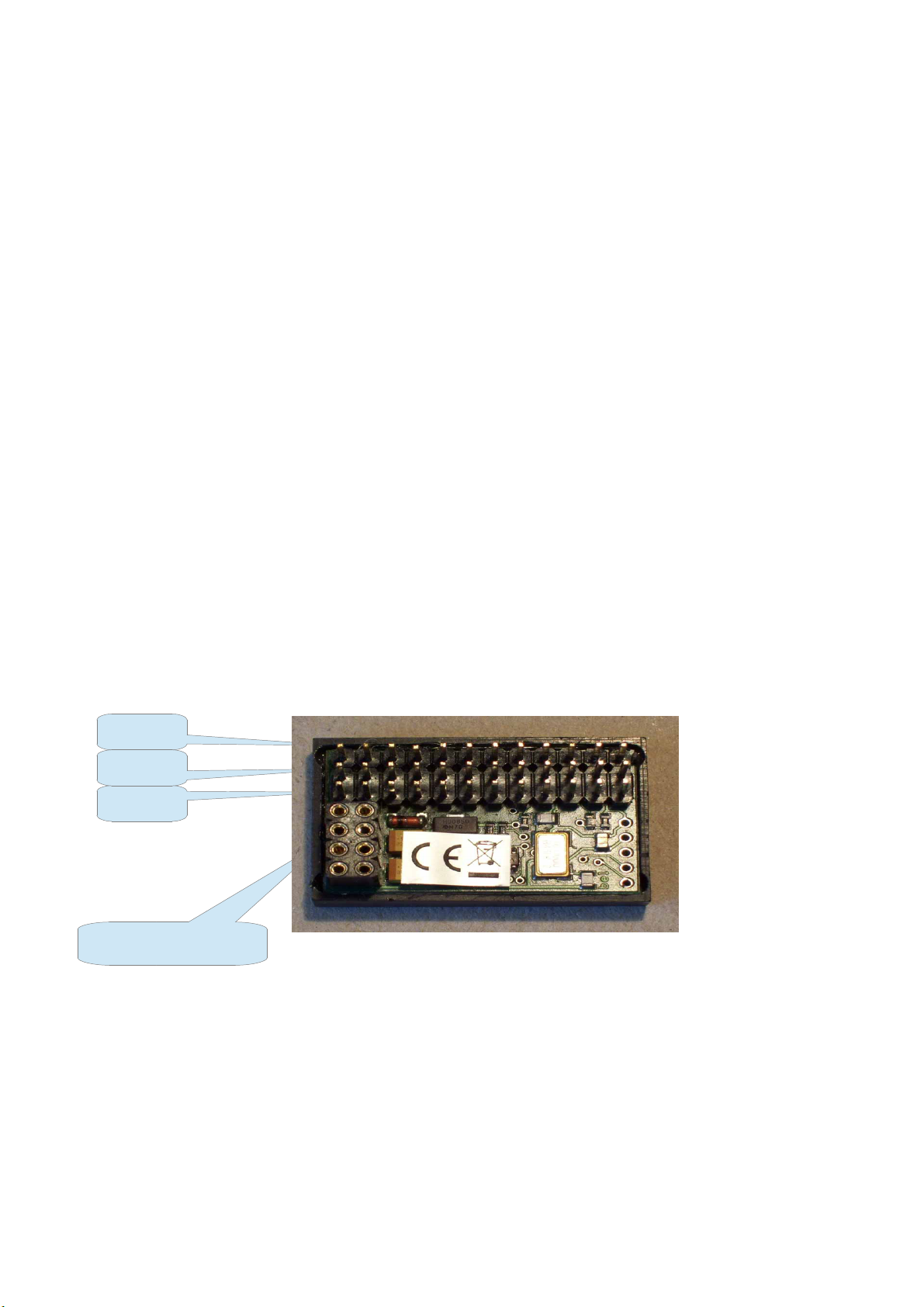
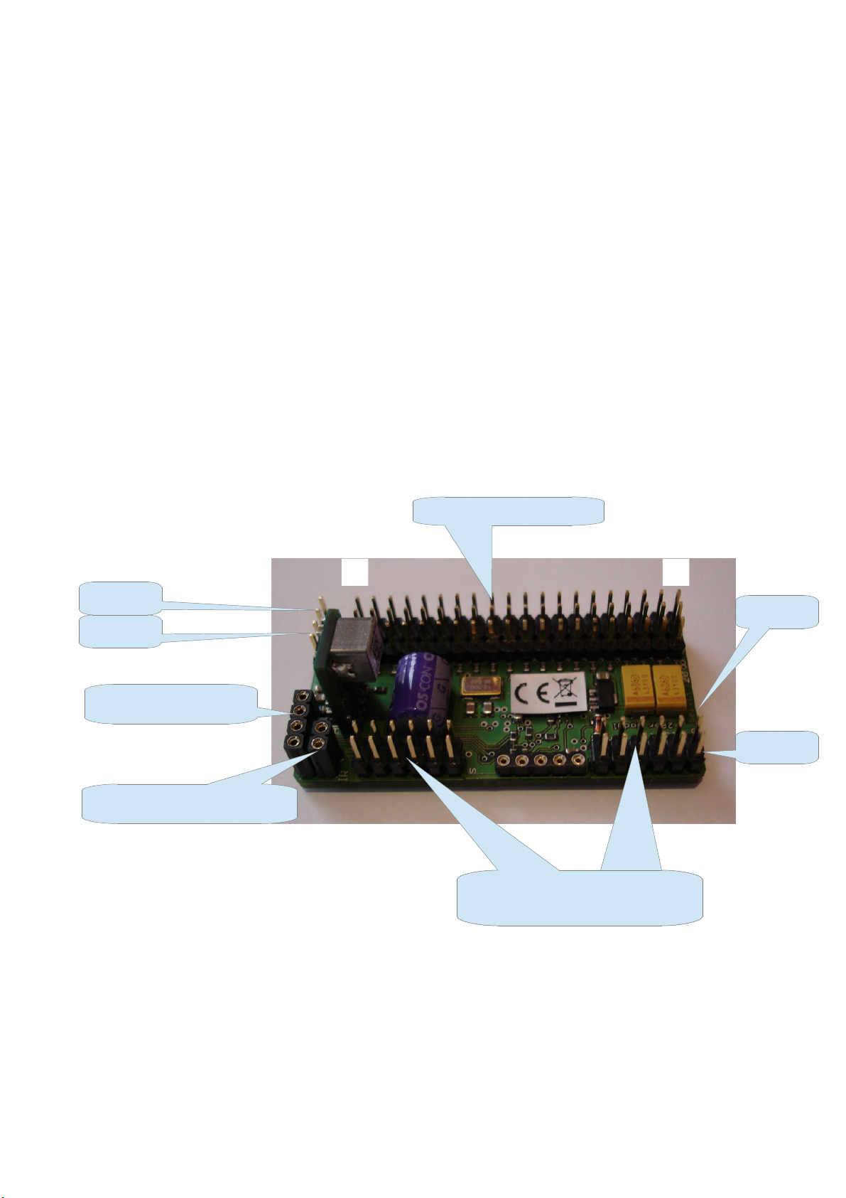
–bc-12er 12 channel receiver bc-20 plus 20 channel receiver
AUS % AUS 0..125% Using a potentiomer this can be used
to switch of this output at a certain
angle of the pot
Tempomat This will enable a cruise control option.
[Cruise control]
Choose an input device (momentary switch recommended) with „Begrenzung mit“ that
can control this feature. This feature will work similar to a „real“ car cruise control. Using
the switch with the throttle stick in any other position than 0 will store this position and you
can release the throttle. The model will hold speed until you either clear the cruise control
with the switch in opposite direction or with the throttle stick in a position higher than the
stored one. Cruise control will be also stoped when moving the throttle stick in reverse
direction. Using the switch with the model in stop and the throttle stick in neutral the
porgrammed throttle position will be used and the model will run with the previously stored
speed.
Begrenzung mit A-z Defines the input device that controls the limitation
[limitation with] (input devices connected to the bc-12er can also control
the limitation]
Ebeneschalter A-z Defines the input device on the transmitter that
[Level control] enables/controls the different levels
Ebenenestellung Defines on which level this output will work
[Level assignment] (use 3 position switch for proper control of the levels)
E+ 0+ A+ works on all levels
E- 0- A+ works just in the upper level(switch up)
E- 0+ A- works just in the mid level(sw. Mid position)
E+ 0- A- works just in the lower level (switch down)
Gegenläufig Nein Normal movement of connected device
[Reverse] [no]
Ja/Invers Reverse movement of connected device
[Yes/Reverse]
..+SigAus Signal will be switched of after 10 sec downtime
[..Signal off] (no change of position of input device)
Offset/Trim -125%..+125% Defines the offset of the connected device
Blindzone -95%..+95% Defines the dead zone around the neutral position.
[Dead zone]
Expo wann 5..95% Defines the turning point of the exponential curve
[Expo. Start at]
Expo wie viel 5..95% Defines the value at the turning point. E.g.
[Expo value] Expo wann 10% and Expo wie viel 50% cause a
10% movement of the connected device at 50% of
23.06.14 Vxx417