manuals.online logo
Brands
  1. Home
  2. •
  3. Brands
  4. •
  5. Broadcast Electronics
  6. •
  7. Transmitter
  8. •
  9. Broadcast Electronics FM-10T User manual

Broadcast Electronics FM-10T User manual

FM–10T
FM–10TS
10 KILOWATT
FM TRANSMITTERS
November, 1998 IM No. 597–0098–014
IMPORTANT INFORMATION
EQUIPMENT LOST OR DAMAGED IN TRANSIT.
When delivering the equipment to you, the truck driver or carrier’s agent will present a receipt for your signature.
Do not sign it until you have: 1) inspected the containers for visible signs of damage and 2) counted the containers
and compared with the amount shown on the shipping papers. If a shortage or evidence of damage is noted, insist
that notation to that effect be made on the shipping papers before you sign them.
Further, after receiving the equipment, unpack it and inspect thoroughly for concealed damage. If concealed dam-
age is discovered, immediately notify the carrier, confirming the notification in writing, and secure an inspection re-
port. This item should be unpacked and inspected for damage WITHIN 15 DAYS after receipt. Claims for loss or
damage will not be honored without proper notification of inspection by the carrier.
RF PRODUCT TECHNICAL ASSISTANCE – REPAIR SERVICE – REPLACEMENT PARTS.
Technical assistance is available from Broadcast Electronics by letter, prepaid telephone, fax, or E–mail. Equip-
ment requiring repair or overhaul should be sent by common carrier, prepaid, insured, and well protected. If proper
shipping materials are not available, contact the Customer Service Department for a shipping container. Do not the
mail equipment. We can assume no liability for inbound damage, and necessary repairs become the obligation of
the shipper. Prior arrangement is necessary. Contact the Customer Service Department for a Return Authoriza-
tion.
Emergency and warranty replacement parts may be ordered from the following address. Be sure to include the
equipment model number, serial number, part description, and part number. Non–emergency replacement parts
may be ordered directly from the Broadcast Electronics stock room by fax at the number shown below.
FACILITY CONTACTS –
Broadcast Electronics, Inc. – Quincy Facility
4100 N. 24th St. P.O. BOX 3606
Quincy, Illinois 62305
Telephone: (217) 224–9600
Fax: (217) 224–9607
E–Mail: General – [email protected]
Web Site: www.bdcast.com
RF PRODUCT TECHNICAL ASSISTANCE – REPAIR – EMERGENCY/WARRANTY REPLACEMENT PARTS –
Telephone: (217) 224–9600
E–Mail: [email protected]
Fax: (217) 224–9607
NON–EMERGENCY REPLACEMENT PARTS –
Fax: (217) 224–9609
RETURN, REPAIR, AND EXCHANGES.
Do not return any merchandise without our written approval and Return Authorization. We will provide special ship-
ping instructions and a code number that will assure proper handling and prompt issuance of credit. Please furnish
complete details as to circumstances and reasons when requesting return of merchandise. All returned merchan-
dise must be sent freight prepaid and properly insured by the customer.
WARRANTY ADJUSTMENT.
Broadcast Electronics, Inc. warranty is included in the Terms and Conditions of Sale. In the event of a warranty
claim, replacement or repair parts will be supplied F.O.B. factory. At the discretion of Broadcast Electronics, the
customer may be required to return the defective part or equipment to Broadcast Electronics, Inc. F.O.B. Quincy,
Illinois. Warranty replacements of defective merchandise will be billed to your account. This billing will be cleared
by a credit issued upon return of the defective item.
PROPRIETARY NOTICE.
This document contains proprietary data of Broadcast Electronics, Inc. No disclosure, reproduction, or use of any
part thereof may be made except by prior written permission.
MODIFICATIONS.
Broadcast Electronics, Inc. reserves the right to modify the design and specifications of the equipment in this manu-
al without notice. Any modifications shall not adversely affect performance of the equipment so modified.
WARNING
OPERATING HAZARDS
READ THIS SHEET AND OBSERVE ALL SAFETY PRECAUTIONS
ALL PERSONS WHO WORK WITH OR ARE EXPOSED TO POWER TUBES, POWER TRANSISTORS, OR EQUIP-
MENT WHICH UTILIZES SUCH DEVICES MUST TAKE PRECAUTIONS TO PROTECT THEMSELVES AGAINST
POSSIBLE SERIOUS BODILY INJURY. EXERCISE EXTREME CARE AROUND SUCH PRODUCTS. UNIN-
FORMED OR CARELESS OPERATION OF THESE DEVICES CAN RESULT IN POOR PERFORMANCE, DAMAGE
TO THE DEVICE OR PROPERTY, SERIOUS BODILY INJURY, AND POSSIBLY DEATH.
DANGEROUS HAZARDS EXIST IN THE OPERATION OF POWER TUBES AND POWER TRANSISTORS
The operation of power tubes and power transistors involves one or more of the following hazards, any one of which,
in the absence of safe operating practices and precautions, could result in serious harm to personnel.
A. HIGH VOLTAGE – Normal operating voltages can be deadly. Additional information follows.
B. RF RADIATION – Exposure to RF radiation may cause serious bodily injury possibly resulting in
blindness or death. Cardiac pacemakers may be affected. Additional information follows.
C. BERYLLIUM – OXIDE POISONING – Dust or fumes from BeO ceramics used as thermal links with
conduction cooled power tubes and power transistors are highly toxic and can cause serious injury or
death. Additional information follows.
D. HOT SURFACES – Surfaces of air–cooled radiators and other parts of tubes can reach temperatures of
several hundred degrees centigrade and cause serious burns if touched. Additional information follows.
E. RF BURNS – Circuit boards with RF power transistors contain high RF potentials. Do not operate an RF
power module with the cover removed.
HIGH VOLTAGE
Many power tubes operate at voltages high enough to kill through electrocution. Personnel should always break the
primary circuits of the power supply and discharge high voltage capacitors when direct access to the tube is required.
RADIO FREQUENCY RADIATION
Exposure of personnel to RF radiation should be minimized, personnel should not be permitted in the vicinity of open
energized RF generating circuits, or RF transmission systems (waveguides, cables, connectors, etc.), or energized
antennas. It is generally accepted that exposure to “high levels” of radiation can result in severe bodily injury includ-
ing blindness. Cardiac pacemakers may be affected.
The effect of prolonged exposure to “low level” RF radiation continues to be a subject of investigation and controver-
sy. It is generally agreed that prolonged exposure of personnel to RF radiation should be limited to an absolute mini-
mum. It is also generally agreed that exposure should be reduced in working areas where personnel heat load is
above normal. A 10 mW/cm2per one tenth hour average level has been adopted by several U.S. Government agen-
cies including the Occupational Safety and Health Administration (OSHA) as the standard protection guide for em-
ployee work environments. An even stricter standard is recommended by the American National Standards Institute
which recommends a 1.0 mW/cm2per one tenth hour average level exposure between 30 Hz and 300 mHz as the
standard employee protection guide (ANSI C95.1–1982).
RF energy must be contained properly by shielding and transmission lines. All input and output RF connections, such
as cables, flanges and gaskets must be RF leakproof. Never operate a power tube without a properly matched RF
energy absorbing load attached. Never look into or expose any part of the body to an antenna or open RF generating
tube or circuit or RF transmission system while energized. Monitor the tube and RF system for RF radiation leakage
at regular intervals and after servicing.
DANGER –– BERYLLIUM OXIDE CERAMICS (BeO) – AVOID BREATHING DUST OR FUMES
BeO ceramic material is used as a thermal link to carry heat from a tube or transistor to the heat sink. Do not perform
any operation on any BeO ceramic which might produce dust or fumes, such as grinding, grit blasting, or acid clean-
ing. Beryllium oxide dust or fumes are highly toxic and breathing them can result in serious personal injury or death.
BeO ceramics must be disposed of only in a manner prescribed by the device manufacturer.
HOT SURFACES
The anode portion of power tubes is often air–cooled or conduction–cooled. The air–cooled external surface normally
operates at a high temperature (up to 200°to 300°C). Other portions of the tube may also reach high temperatures,
especially the cathode insulator and the cathode/heater surfaces. All hot surfaces may remain hot for an extended
time after the tube is shut off. To prevent serious burns, take care to prevent and avoid any bodily contact with these
surfaces both during and for a reasonable cooling down period after tube operation.
-1 -
PUBLICATION ADDENDUM
SPECIAL ASSEMBLY REQUIREMENTS
FM-10T/FM-10TS TRANSMITTER
1-1. INTRODUCTION.
1-2. Due to special shipping requirements, selected components of the Broadcast Electronics
FM-10T/FM-10TS transmitter have been disassembled to prevent damage during ship
ment. This publication addendum provides information required for the re-assembly of
the transmitter IN ADDITION TO the information provided in SECTION II, INSTALLA
TION. Perform the following assembly instructions before proceeding to the procedures
described in this manual.
1-3. SPECIAL ASSEMBLY.
1-4. GENERAL. Components removed from the transmitter for shipment contain identification
tags to permit reinstallation. Items such as interconnecting wires, cables, and miscellane
ous small parts are taped or tied in for shipment. Remove all tape, string, and packing ma
terial used for shipping purposes as each item is installed.
1-5. Terminal blocks and wires contain identification tags with information regarding reconnec
tion. Mounting hardware will be placed in small bags attached to each removed compo
nent or inserted in the component mounting holes.
WARNING
WARNING
ENSURE NO PRIMARY POWER IS CONNECTED TO
THE TRANSMITTER BEFORE PROCEEDING.
1-6. FM-10T HIGH VOLTAGE POWER SUPPLY CABINET. Install components removed from
the FM-10T high voltage power supply cabinet by performing the following procedures.
Ensure no primary power is connected to the transmitter before attempting any component
installation.
1-7. 220V AC Power Supply Operation. For 220V ac power supply transmitters, refer to Fig
ure 1 and install the components in the power supply cabinet by performing the following
procedures.
1-8. Install the plate choke as follows:
A. Place the plate choke in the proper position on the power supply cabinet
base-plate.
B. Connect wires 540, 546, and 565 to the plate choke as shown.
1-9. Install the plate transformer as follows:
A. Place the plate transformer in the proper position on the power
supply cabinet base-plate.
-2-
COPYRIGHT 1997 BROADCAST ELECTRONICS, INC
597-0098-411
FIGURE 1. FM-10T POWER SUPPLY BASE-PLATE INSTALLATION, 220V POWER SOURCE
-3 -
WARNING
WARNING
ENSURE THE GROUND STRAP ON THE PLATE
TRANSFORMER IS PROPERLY INSTALLED.
B. Mount the plate transformer to the base-plate as shown. Ensure the
ground strap is properly installed on the transformer mounting bracket.
C. Connect wires 505 through 507 to the plate transformer primary as shown.
D. Connect wires 541 through 543 to the plate transformer secondary as shown.
1-10. Remove the jumper wires between the terminals on plate supply capacitors C5 and C18.
1-11. 380V AC Power Supply Operation. For 380V ac power supply transmitters, refer to Fig
ure 2 and install the components in the power supply cabinet by performing the following
procedures.
1-12. Install the plate choke as follows:
A. Place the plate choke in the proper position on the power supply
cabinet base-plate.
B. Connect wires 540, 546, and 565 to the plate choke as shown.
1-13. Install the plate transformer as follows:
A. Place the plate transformer in the proper position on the power
supply cabinet base-plate.
WARNING
WARNING
ENSURE THE GROUND STRAP ON THE PLATE
TRANSFORMER IS PROPERLY INSTALLED.
B. Mount the plate transformer to the base-plate as shown. Ensure the
ground strap is properly installed on the transformer mounting bracket.
C. Connect wires 505, 506, 507, and 580 to the plate transformer primary
as shown.
D. Connect wires 541, 542, 543, and 578 to the plate transformer
secondary as shown.
1-14. Remove the jumper wires between the terminals on plate supply capacitors C5 and C18.
WARNING
WARNING
ENSURE NO PRIMARY POWER IS CONNECTED TO
THE TRANSMITTER BEFORE PROCEEDING.
1-15. FM-10TS HIGH VOLTAGE POWER SUPPLY CABINET. Install components removed from
the FM-10TS high voltage power supply cabinet by performing the following procedures.
Ensure no primary power is connected to the transmitter before attempting any component
installation.
-4-
COPYRIGHT 1990 BROADCAST ELECTRONICS, INC
597-0098-100
FIGURE 2. POWER SUPPLY BASE-PLATE INSTALLATION, 380V POWER SOURCE
-5 -
1-16. Plate Supply Chokes. Refer to Figure 3 and install the plate chokes as follows:
A. Place plate supply chokes L2 and L3 in the proper position on the power supply
cabinet base-plate.
B. Connect wires 584, 546, and 565 to L2 as shown.
C. Connect wires 543, 580, 583, and 582 to L3 as shown.
FIGURE 3. FM-10TS POWER SUPPLY BASE-PLATE INSTALLATION
597-0098-32
COPYRIGHT 1990 BROADCAST ELECTRONICS, INC
1-17. Plate Supply Transformer. Refer to Figure 3 and install the plate transformer as follows:
A. Place the plate transformer in the proper position on the power supply cabinet
base-plate.
WARNING
WARNING
ENSURE THE GROUND STRAP ON THE PLATE
TRANSFORMER IS PROPERLY INSTALLED.
B. Mount the plate transformer to the base-plate as shown. Ensure the
ground strap is properly installed on the transformer mounting bracket.
C. Connect wires 502 and 503 to the plate transformer primary as shown.
D. Connect wires 541 and 542 to the plate transformer secondary as shown.
1-18. Plate Supply Capacitors. Remove the jumper wires between the terminals on plate supply
capacitors C5 and C18.
-6-
WARNING
WARNING
ENSURE NO PRIMARY POWER IS CONNECTED TO
THE TRANSMITTER BEFORE PROCEEDING.
1-19.PA/DRIVER CABINET. Install components removed from the PA/driver cabinet by per
forming the following procedures. Ensure no primary power is connected to the transmit
ter before attempting any component installation.
1-20. FM-250C Exciter. Remove the exciter from the shipping container.
1-21. If required, refer to the FM-10T/FM-10TS installation diagram in SECTION II, INSTAL
LATION of the instruction manual for the location of the FM-250C exciter in the PA/driver
cabinet. Install the exciter by lifting the unit onto the slide rails.
1-22. Refer to Figure 4 and attach the following cables to the exciter rear-panel receptacles.
WIRE OR CABLE IDENTIFICATION EXCITER REAR-PANEL RECEPTACLE
133 RF OUTPUT
EXCITER AC INPUT AC INPUT
EXCITER CABLE HARNESS TB1
1-23. Blower Assembly. Unpack the blower assembly by removing the shipping strap securing
the assembly to the cabinet chassis.
-7 -
COPYRIGHT 1990 BROADCAST ELECTRONICS, INC
597-0098-408
FIGURE 4. FM-250C REAR-PANEL CONNECTIONS
-i -
Broadcast Electronics 1997
ALL RIGHTS RESERVED
Printed in the U.S.A.
SCOPE OF MANUAL
This manual consists of two sections and provides the following information for the Broadcast
Electronics FM-10T/FM-10TS transmitters.
A. PART I - Contains information relative to installation, operation, and
maintenance applicable to the overall transmitter.
B. PART II - Contains detailed information for the following transmitter
modular units.
TRANSMITTER CONTROLLER
PART I - TABLE OF CONTENTS
PARAGRAPH PAGE NO.
SECTION I GENERAL INFORMATION
1-1 INTRODUCTION 1-1
1-3 RELATED PUBLICATIONS 1-1
1-5 EQUIPMENT DESCRIPTION 1-1
1-7 TRANSMITTER CONFIGURATIONS 1-1
1-9 ACCESSORIES AND SPARE PARTS KITS 1-3
1-11 EQUIPMENT SPECIFICATIONS 1-3
SECTION II INSTALLATION
2-1 INTRODUCTION 2-1
2-3 UNPACKING 2-1
2-6 INSTALLATION REQUIREMENTS 2-1
2-7 ENVIRONMENTAL 2-1
2-9 COOLING AIR 2-1
2-13 PRIMARY POWER 2-1
2-14 FM-10T 2-1
2-17 FM-10TS 2-2
2-18 INSTALLATION 2-2
2-20 EQUIPMENT PLACEMENT 2-2
2-25 COMPONENT INSTALLATION 2-2
2-28 HIGH VOLTAGE POWER SUPPLY CABINET 2-6
2-33 PA/DRIVER CABINET 2-6
2-59 REMOTE CONTROL 2-8
2-95 WIRING 2-14
2-96 TRANSFORMER TAPS 2-14
2-97 INPUT VOLTAGE CHECK 2-14
2-98 CABINET INTERCONNECTIONS 2-14
2-101 OPTIONAL EQUIPMENT WIRING 2-19
2-102 SIGNAL INPUTS 2-19
2-103 FAILSAFE INTERLOCK 2-19
2-104 TRANSMITTER MONITORING - MODEM 2-19
CONNECTIONS
2-105 TRANSMITTER MONITORING - PRINTER 2-20
CONNECTIONS
2-106 AC POWER CONNECTIONS 2-20
-ii -
PARAGRAPH PAGE NO.
2-107 FM-10T 2-20
2-109 FM-10TS 2-22
2-111 INITIAL CHECKOUT 2-22
2-119 CONTROLLER AND INTERLOCK CHECKOUT 2-24
2-139 BLOWER CHECKOUT 2-26
2-143 EXCITER CHECKOUT 2-26
2-153 PRELIMINARY OPERATION AND TUNING 2-26
SECTION III OPERATION
3-1 INTRODUCTION 3-1
3-3 CONTROLS AND INDICATORS 3-1
3-5 OPERATION 3-1
3-6 TURN ON 3-1
3-16 TURN OFF 3-5
3-18 OPERATING THE TRANSMITTER FOR MAXIMUM 3-5
TUBE LIFE
SECTION IV THEORY OF OPERATION
4-1 INTRODUCTION 4-1
4-4 ELECTRICAL DESCRIPTION 4-1
4-5 FM EXCITER 4-1
4-8 POWER AMPLIFIER 4-1
4-10 POWER AMPLIFIER CAVITY 4-1
4-11 OUTPUT COUPLING 4-1
4-12 OUTPUT TUNING 4-2
4-13 NEUTRALIZATION 4-2
4-14 SECOND HARMONIC SUPPRESSOR 4-2
4-15 OUTPUT CIRCUIT 4-2
4-16 TRANSMITTER CONTROLLER 4-2
4-22 AUTOMATIC RF OUTPUT LEVEL CONTROL 4-5
4-24 VSWR FOLDBACK PROTECTION 4-5
4-25 SOFT START 4-5
4-26 MOMENTARY POWER INTERRUPTION 4-5
4-27 OVERLOADS 4-5
4-28 INDICATORS 4-5
4-30 METERING 4-6
4-33 EXCITER METERING 4-6
4-34 POWER SUPPLIES 4-6
4-40 DETAILED DESCRIPTION 4-6
4-41 POWER SUPPLIES 4-6
4-43 SEQUENCE OF OPERATION 4-11
4-49 FM-10T PA PLATE POWER SUPPLY 4-11
4-53 FM-10TS PA PLATE POWER SUPPLY 4-12
4-57 PA SCREEN POWER SUPPLY 4-12
4-58 PA CONTROL GRID BIAS POWER SUPPLY 4-13
4-60 PA FILAMENT SUPPLY 4-13
4-61 RF CIRCUITRY 4-13
4-62 FM EXCITER 4-13
4-63 POWER AMPLIFIER 4-13
4-72 PA METERING 4-14
4-73 AUTOMATIC POWER CONTROL 4-14
-iii -
PARAGRAPH PAGE NO.
SECTION V MAINTENANCE
5-1 INTRODUCTION 5-1
5-3 SAFETY CONSIDERATIONS 5-1
5-9 FIRST LEVEL MAINTENANCE 5-2
5-11 MISCELLANEOUS 5-2
5-13 CONTROLLER BATTERY 5-2
5-15 AIR FILTER 5-2
5-18 BLOWER MAINTENANCE 5-3
5-22 SECOND LEVEL MAINTENANCE 5-3
5-24 GENERAL 5-3
5-25 PA STAGE 5-3
5-27 ADJUSTMENTS 5-4
5-29 AM NOISE 5-5
5-38 CONTROL GRID BIAS LEVEL ADJUSTMENT 5-5
5-39 PLATE CURRENT METER CALIBRATION 5-6
5-40 SECOND HARMONIC SUPPRESSOR 5-6
5-63 NEUTRALIZATION 5-9
5-95 TRANSMITTER POWER LEVEL CHANGE 5-12
5-97 TRANSMITTER FREQUENCY CHANGE 5-12
PROCEDURE
5-98 GENERAL 5-12
5-110 TROUBLESHOOTING 5-15
5-113 COMPONENT REPLACEMENT ON CIRCUIT 5-16
BOARDS
SECTION VI PARTS LISTS
6-1 INTRODUCTION 6-1
SECTION VII DRAWINGS
7-1 INTRODUCTION 7-1
APPENDIX A MANUFACTURERS DATA
A-1 INTRODUCTION A-1
LIST OF TABLES
TABLE NO. TITLE PAGE NO.
1-1 FM-10T/FM-10TS ELECTRICAL SPECIFICATIONS 1-4
1-2 FM-10T/FM-10TS PHYSICAL AND ENVIRONMENTAL 1-6
SPECIFICATIONS
3-1 FM-10T/FM-10TS POWER SUPPLY CABINET CONTROLS 3-5
AND INDICATORS
3-2 FM-10T/FM-10TS PA/DRIVER CABINET CONTROLS AND 3-6
INDICATORS
3-3 INDICATOR CHECKLIST 3-10
5-1 FM-10T/FM-10TS TYPICAL METER INDICATIONS, 5-15
10kW POWER OUTPUT
5-2 FM-10T TYPICAL POWER DEMAND, 10 kW POWER OUTPUT 5-16
5-3 FM-10TS TYPICAL POWER DEMAND, 10 kW POWER 5-16
OUTPUT
-iv -
TABLE NO. TITLE PAGE NO.
6-1 REPLACEABLE PARTS LISTS 6-1
LIST OF ILLUSTRATIONS
FIGURE NO. TITLE PAGE NO.
1-1 FM-10T TRANSMITTER 1-2
2-1 FM-10T/FM-10TS INSTALLATION DIAGRAM 2-3
2-2 ACCEPTABLE AC POWER INPUT CONFIGURATIONS 2-5
2-3 FM-10T/FM-10TS RF OUTPUT TRANSMISSION LINE 2-8
CONNECTION
2-4 REMOTE CONTROL INTERFACING 2-9
2-5 TRANSFORMER TAPS 2-15
2-6 CABINET INTERCONNECTIONS, ADJACENT POWER 2-16
SUPPLY CABINET INSTALLATIONS
2-7 CABINET INTERCONNECTIONS, REMOTE POWER 2-18
SUPPLY CABINET INSTALLATIONS
2-8 OPTIONAL EQUIPMENT WIRING 2-20
2-9 FM-10T PRIMARY AC WIRING 2-21
2-10 FM-10TS PRIMARY AC WIRING 2-23
3-1 FM-10T/FM-10TS POWER SUPPLY CABINET CONTROLS 3-2
AND INDICATORS
3-2 FM-10T/FM-10TS PA/DRIVER CABINET CONTROLS AND 3-3
INDICATORS
4-1 FM-10T/FM-10TS BLOCK DIAGRAM 4-3
4-2 FM-10T POWER SUPPLY SIMPLIFIED SCHEMATIC 4-7
4-3 FM-10TS POWER SUPPLY SIMPLIFIED SCHEMATIC 4-9
4-4 RF CIRCUIT SIMPLIFIED SCHEMATIC 4-15
4-5 PA CAVITY 4-17
5-1 FM-10T/FM-10TS TYPICAL PA EFFICIENCY 5-4
5-2 HUM NULL CONTROL LOCATION 5-6
5-3 SECOND HARMONIC SUPPRESSOR ADJUSTMENT 5-8
5-4 PA NEUTRALIZATION 5-11
5-5 COARSE TUNING ADJUSTMENTS 5-14
5-6 FM-10T POWER SUPPLY CABINET COMPONENT LOCATOR 5-18
5-7 FM-10T/FM-10TS PA/DRIVER CABINET COMPONENT 5-19
LOCATOR
5-8 PA CAVITY COMPONENT LOCATOR 5-20
5-9 PA INPUT CIRCUIT COMPONENT LOCATOR 5-21
5-10 TRANSMISSION LINE AND LOW-PASS FILTER ASSEMBLY 5-22
5-11 FM-1OTS POWER SUPPLY CABINET COMPONENT 5-23
LOCATOR
PART II - TABLE OF CONTENTS
I - TRANSMITTER CONTROLLER
1-1
SECTION I
GENERAL INFORMATION
1-1. INTRODUCTION.
1-2. Information presented by this section provides a general description of the Broadcast
Electronics FM-10T/FM-10TS transmitters and lists equipment specifications.
1-3. RELATED PUBLICATIONS.
1-4. The following list of publications provides data for equipment associated with the
FM-10T/FM-10TS transmitters.
PUBLICATION NUMBER EQUIPMENT
597-1004 FM-250C FM Exciter
597-0008-004 FC-30 SCA Generator
597-9900 LYNX FM Digital Stereo Generator
597-8000 PREDATOR FM Digital Exciter
597-9091 RTDS - Remote Transmitter Diagnostic
System
1-5. EQUIPMENT DESCRIPTION.
1-6. The Broadcast Electronics FM-10T and FM-10TS are one-tube 10 kW FM transmitters
designed for continuous operation in the 87.5 MHz to 108 MHz FM broadcast band (refer
to Figure 1-1). Specific transmitter features include: 1) a folded half-wave cavity PA
stage, 2) a microprocessor control system, and 3) a 250 watt solid-state exciter with a digi
tal frequency synthesizer. The RF power amplifier, FM exciter, and control circuitry is
housed in a single cabinet. A high voltage power supply is housed in a separate cabinet
which may be located remotely from the PA/driver cabinet if desired. The following text
provides ordering information for various transmitter configurations, optional equipment,
and accessories and recommended spare parts kits.
1-7. TRANSMITTER CONFIGURATIONS.
1-8. The FM-10T/FM-10TS transmitters may be ordered in the following configurations:
MODEL NO. PART NUMBER DESCRIPTION
FM-10T 909-1110-205 FM-10T Transmitter complete with FM-250C FM Exciter,
1 5/8 inch low-pass filter, 208/240V ac three-phase 60 Hz
operation, high voltage power supply adjacent to PA/driver
cabinet.
FM-10T 909-1110-305 FM-10T Transmitter complete with FM-250C FM Exciter,
1 5/8 inch low-pass filter, 208/240V ac three-phase 50 Hz
operation, high voltage power supply adjacent to PA/driver
cabinet.
FM-10T 909-1110-385 FM-10T Transmitter complete with FM-250C FM Exciter,
1 5/8 inch low-pass filter, 339/437V ac three-phase 50 Hz
operation, high voltage power supply adjacent to PA/driver
cabinet.
FM-10TS 909-1110-255 FM-10TS Transmitter complete with FM-250C FM
Exciter, 1 5/8 inch low-pass filter, 208/240V ac single-
phase 60/50 Hz operation, high voltage power supply
adjacent to PA/driver cabinet.
1-2
FIGURE 1-1. FM-10T TRANSMITTER
597-0098-1
COPYRIGHT 1997 BROADCAST ELECTRONICS, INC
MODEL NO. PART NUMBER DESCRIPTION
---- 909-0136 Remote Power Supply Cabinet Configuration.
FM-10T 909-1110-306 FM-10T Transmitter complete with FM-250C FM Exciter,
3 1/8 inch low-pass filter, 208/240V ac three-phase 50 Hz
operation, high voltage power supply adjacent to PA/driver
cabinet.
FM-10T 909-1110-386 FM-10T Transmitter complete with FM-250C FM Exciter,
3 1/8 inch low-pass filter, 339/437V ac three-phase 50 Hz
operation, high voltage power supply adjacent to PA/driver
cabinet.
FM-10T 909-1110-206 FM-10T Transmitter complete with FM-250C FM Exciter,
3 1/8 inch low-pass filter, 208/240V ac three-phase 60 Hz
operation, high voltage power supply adjacent to PA/driver
cabinet.
1-3
MODEL NO. PART NUMBER DESCRIPTION
FM-10TS 909-1110-256 FM-10TS Transmitter complete with FM-250C FM
Exciter, 3 1/8 inch low-pass filter, 208/240V ac single-
phase 60/50 Hz operation, high voltage power supply
adjacent to PA/driver cabinet.
1-9. ACCESSORIES AND SPARE PARTS KITS.
1-10. The following accessory products and spare parts kits are available for use in the
FM-10T/FM-10TS transmitters:
PART NUMBER DESCRIPTION
909-9000 LYNX FM digital stereo generator.
909-0051-204 FC-30 FM SCA generator.
909-8250 PREDATOR 250 Watt FM Digital Exciter And Digital
Input.
909-8251 PREDATOR 250 Watt FM Digital Exciter And Analog
Input.
909-8252 PREDATOR 250 Watt FM Analog Exciter And Analog
Input.
979-0094 Recommended spare parts kit for the FM-10T/
FM-10TS and FM-250C exciter. Includes selected
meters, switches, relays etc. Does not include
semi-conductors.
979-0095 Recommended spare semiconductor kit for the
FM-10T/FM-10TS and FM-250C exciter.
979-0095-005 Recommended spare semiconductor kit for the
FM-10T/FM-10TS transmitters only. Does not
include exciter spare semiconductors.
979-0094-005 Recommended spare parts kit for the FM-10T/
FM-10TS transmitter only. Includes selected meters,
switches, relays, etc. Does not include
semiconductors.
979-0133-014 Recommended spare HV rectifier kit for the FM-10T
transmitter.
907-0016-054 VMC-16 Voice Remote Control Unit, FM-10T/
FM-10TS.
909-9091 RTDS (Remote Transmitter Diagnostic System) for
T-Series transmitters. A Windows 95 software
product designed to allow a user to control transmitter
operations and diagnose transmitter problems from a
remote location. Factory installation.
909-9091-001 RTDS (Remote Transmitter Diagnostic System) for
T-Series transmitters. A Windows 95 software
product designed to allow a user to control transmitter
operations and diagnose transmitter problems from a
remote location. Field installation.
1-11. EQUIPMENT SPECIFICATIONS.
1-12. Refer to Table 1-1 for the electrical specifications and Table 1-2 for the physical and envi
ronmental specifications of the Broadcast Electronics FM-10T/FM-10TS transmitters.
1-4
TABLE 1-1. FM-10T/FM-10TS ELECTRICAL SPECIFICATIONS
(Sheet 1 of 2)
PARAMETER SPECIFICATION
RF POWER OUTPUT 4.5 kW to 11.0 kW (as specified).
FREQUENCY RANGE 87.5 to 108 MHz (as specified).
Exciter programmable in 10 kHz increments.
RF OUTPUT IMPEDANCE 50 Ohms, resistive (others available by special
request).
RF OUTPUT CONNECTOR 1 5/8 inch coupling standard. 3 1/8 inch EIA
flange optional.
MAXIMUM VSWR 1.8:1 (will operate into a higher VSWR with
automatic power reduction).
TUBE COMPLEMENT 4CX7500A
AM SIGNAL-TO-NOISE RATIO:
Asynchronous 55 dB below an equivalent reference carrier with
100% AM modulation @ 400 Hz, 75 microsecond
deemphasis (no FM modulation present).
Synchronous 45 dB below an equivalent 10 kW reference car-
rier with 100% AM modulation @ 1 kHz, no de-
emphasis (FM modulation: ±75 kHz @ 1 kHz).
FM SIGNAL-TO-NOISE RATIO:
Mono/Composite 85 dB below ±75 kHz deviation @ 400 Hz meas-
ured in a 20 Hz to 30 kHz bandwidth with 75
microsecond deemphasis.
Stereo 80 dB or better below 100% modulation @ 400 Hz,
measured in a 20 Hz to 30 kHz bandwidth with
75 microsecond deemphasis.
DISTORTION
Mono/Composite
Harmonic 0.03% or less at 400 Hz.
SMPTE Intermodulation 0.05% or less, 60 Hz/7 kHz, Ratio:
Distortion 4:1 Monophonic, 1:1 Composite.
CCIF Intermodulation
Distortion
Mono 0.02% or less, 15 kHz/14 kHz, 1:1 Ratio.
Composite 0.03% or less, 15 kHz/14 kHz, 1:1 Ratio.
Transient Intermodulation 0.02% or less, sine wave/square wave.
Distortion
1-5
TABLE 1-1. FM-10T/FM-10TS ELECTRICAL SPECIFICATIONS
(Sheet 2 of 2)
PARAMETER SPECIFICATION
DISTORTION (Con't)
Stereo
Harmonic 0.05% or less at 400 Hz.
SMPTE Intermodulation 0.08% or less, 60 Hz/7 kHz, 4:1 Ratio.
Distortion
CCIF Intermodulation 0.05% or less, 15 kHz/14 kHz, 1:1 Ratio.
Distortion
Transient Intermodulation 0.05% or less, sine wave/square wave.
Distortion
STEREO SEPARATION 50 dB or better, 30 Hz to 15 kHz.
DYNAMIC STEREO SEPARATION 40 dB or better, 30 Hz to 15 kHz (normal program
content).
LINEAR CROSSTALK 45 dB Minimum below 100% modulation,
(Main to Sub/Sub to Main 30 Hz to 15 kHz.
Due to Phase Matching)
NON-LINEAR CROSSTALK 70 dB Minimum below 100% modulation.
(Main to Sub/Sub to Main
Due to Distortion Products)
RF HARMONIC SUPPRESSION Meets all FCC/DOC requirements and CCIR
recommendations.
POWER SUPPLY RECTIFIERS Silicon.
AC POWER REQUIREMENTS
FM-10T 196 to 252V ac 50/60 Hz or 341V to 435V ac 50
Hz, three-phase closed-Delta or Wye (as speci-
fied).
FM-10TS 196 to 252V ac 50/60 Hz single-phase.
AC POWER CONSUMPTION
FM-10T 15.8 kW typical at a 10 kW RF power output, 0.94
power factor.
FM-10TS 20.0 kW typical at a 10 kW RF power output, 0.97
power factor.
PA EFFICIENCY 80% typical.
OVERALL EFFICIENCY
FM-10T 63% typical (AC line input to RF output).
FM-10TS 50% typical (AC line input to RF output).
1-6
TABLE 1-2. FM-10T/FM-10TS PHYSICAL AND ENVIRONMENTAL SPECIFICATIONS
PARAMETER SPECIFICATION
PHYSICAL
DIMENSIONS:
PA/Driver Cabinet Width: 33.7 inches (85.6 cm).
Height: 70 inches (177.8 cm).
Depth: 37.2 inches (94.49 cm).
High Voltage Power Width: 22.7 inches (57.66 cm).
Supply Cabinet Height: 70 inches (177.8 cm).
Depth: 37.2 inches (94.49 cm).
WEIGHT:
PA/Driver Cabinet 810 pounds (367 kg).
High Voltage Power 1000 pounds (453.6 kg).
Supply Cabinet
CUBAGE:
PA/Driver Cabinet 53 cubic feet (1.5 m3).
High Voltage Power 36 cubic feet (1.01 m3).
Supply Cabinet
ENVIRONMENTAL
HEAT DISSIPATION (10 kw
OUTPUT)
FM-10T 5.8 kW (19,795 BTU/H).
FM-10TS 10 kW (34,130 BTU/H).
COOLING AIR REQUIREMENTS 800 cubic feet per minute (22.6 m3/min).
AMBIENT TEMPERATURE RANGE +14°F to +122°F (-10°C to +50°C).
MAXIMUM ALTITUDE
50 Hz Models 0 to 7,500 feet above sea level (0 to 2286 meters).
60 Hz Models 0 to 10,000 feet above sea level (0 to 3048 meters).
MAXIMUM HUMIDITY 95%, non-condensing.

This manual suits for next models

1

Other Broadcast Electronics Transmitter manuals

Broadcast Electronics AM-6A User manual

Broadcast Electronics

Broadcast Electronics AM-6A User manual

Broadcast Electronics PNP 1000 User manual

Broadcast Electronics

Broadcast Electronics PNP 1000 User manual

Broadcast Electronics AM-500A 500 WATT User manual

Broadcast Electronics

Broadcast Electronics AM-500A 500 WATT User manual

Broadcast Electronics FX-50 User manual

Broadcast Electronics

Broadcast Electronics FX-50 User manual

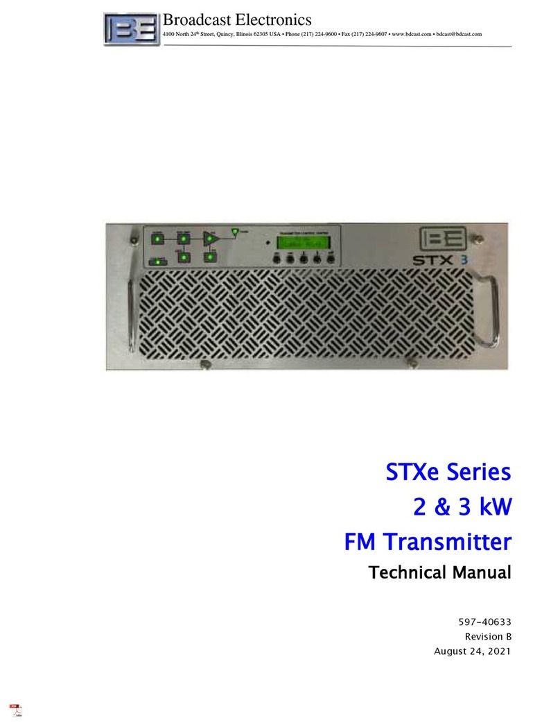
Broadcast Electronics STXe Series User manual

Broadcast Electronics

Broadcast Electronics STXe Series User manual

Broadcast Electronics AM-500A User manual

Broadcast Electronics

Broadcast Electronics AM-500A User manual

Broadcast Electronics 4MX 100 User manual

Broadcast Electronics

Broadcast Electronics 4MX 100 User manual

Broadcast Electronics AM-2.5E User manual

Broadcast Electronics

Broadcast Electronics AM-2.5E User manual

Broadcast Electronics FM-5T User manual

Broadcast Electronics

Broadcast Electronics FM-5T User manual

Popular Transmitter manuals by other brands

ELT ELT406GPS Installation, operating and maintenance manual

ELT

ELT ELT406GPS Installation, operating and maintenance manual

MTT MS3702B user manual

MTT

MTT MS3702B user manual

M-system 6BVS instruction manual

M-system

M-system 6BVS instruction manual

Dakota Alert WPT-3000 owner's manual

Dakota Alert

Dakota Alert WPT-3000 owner's manual

Ritron RQA-450 owner's manual

Ritron

Ritron RQA-450 owner's manual

Alesis GuitarLink Wireless user guide

Alesis

Alesis GuitarLink Wireless user guide

Gold Apollo TE-300 user manual

Gold Apollo

Gold Apollo TE-300 user manual

Akura ATW-GA2929 instruction manual

Akura

Akura ATW-GA2929 instruction manual

signia 650003 user guide

signia

signia 650003 user guide

Spektrum DX10t instruction manual

Spektrum

Spektrum DX10t instruction manual

Weiking BT06-T user manual

Weiking

Weiking BT06-T user manual

WM Systems WM-I3 user manual

WM Systems

WM Systems WM-I3 user manual

DSE RE-HDMI-RG owner's manual

DSE

DSE RE-HDMI-RG owner's manual

YOKOGAWA EJX115A user manual

YOKOGAWA

YOKOGAWA EJX115A user manual

Sennheiser SK 2012-90 manual

Sennheiser

Sennheiser SK 2012-90 manual

NAPCO GEM-TRANSLP installation instructions

NAPCO

NAPCO GEM-TRANSLP installation instructions

RKI Instruments 65-2670-XX-04 Operator's manual

RKI Instruments

RKI Instruments 65-2670-XX-04 Operator's manual

Continental Refrigerator T2x user manual

Continental Refrigerator

Continental Refrigerator T2x user manual

manuals.online logo
manuals.online logoBrands
  • About & Mission
  • Contact us
  • Privacy Policy
  • Terms and Conditions

Copyright 2025 Manuals.Online. All Rights Reserved.