Broadcast Electronics STXe Series User manual

Broadcast Electronics
4100 North 24th Street, Quincy, Illinois 62305 USA • Phone (217) 224-9600 • Fax (217) 224-9607 • www.bdcast.com • [email protected]
STXe Series
2& 3kW
FM Transmitter
Technical Manual
597-40633
Revision B
August 24, 2021

STXeSeries – 2 & 3kW FM Transmitters
Technical Manual
©2020 Broadcast Electronics all rights reserved.
The information in this publication is subject to improvement and change without notice. Although every
effort is made to ensure the accuracy of the information in this manual, Broadcast Electronics accepts no
responsibility for any errors or omissions. Broadcast Electronics reserves the right to modify and improve
the design and specifications of the equipment in this manual without notice. Any modifications shall not
adversely affect performance of the equipment so modified.
Proprietary Notice
This document contains proprietary data of Broadcast Electronics. No part of this publication may be
reproduced, transmitted, transcribed, stored in a retrieval system, translated into any other language in
any form or by any means, electronic or mechanical, including photocopying or recording, for any
purpose, without the express written permission of Broadcast Electronics.
Trademarks
Broadcast Electronics and the BE logo are registered trademarks of Broadcast Electronics.
Marti Electronics and the Marti logo are registered trademarks of Broadcast Electronics.
All other trademarks are property of their respective owners.
Copyright
Copyright laws protect artwork depicting circuitry in this manual.
Information in this manual is subject to change without notice and does not represent a commitment on
the part of Broadcast Electronics.
Broadcast Electronics may make improvements and/or changes in this manual or in the product described
herein at any time.
This product could include technical inaccuracies or typographical errors.

i
©2020 Broadcast Electronics
Broadcast Electronics Product Warranty
Broadcast Electronics hereby warrants all new products manufactured by Broadcast Electronics against
any defects in material or workmanship at the time of delivery thereof, or that develop under normal use
within the period from the date of shipment.
Broadcast Electronics reserves the right to repair equipment under warranty with new or refurbished
equipment or parts. Broadcast Electronics’ sole responsibility, with respect to any equipment or parts not
conforming to this warranty, is to replace or repair such equipment upon the return thereof F.O.B. to
Broadcast Electronics’ factory in Quincy, Illinois, U.S.A. In the event of replacement pursuant to the
foregoing warranty, only the unexpired portion of the warranty from the time of the original purchase will
remain in effect for any such replacement.
This warranty shall exclude the following products, component parts and/or assemblies:
(a) Transmitter power output tubes shall only carry the original manufacturers’ or suppliers’
standard warranty in effect on their original shipment date.
(b) All computers, computer peripherals, cables, hard disk drives, etc., shall only carry the
manufacturers’ or suppliers’ standard warranty in effect on their original shipment date.
(c) “Components”, defined as separate and individual parts (e.g. transistors, integrated circuits,
capacitors, resistors, inductors, fans, etc.), resold by Broadcast Electronics from another manufacturer or
supplier, shall only carry a 90-day warranty, effective the date of shipment. Any such “Components” being
returned for warranty claim must be (1) returned in their original packaging and (2) must be in new,
unused condition. Broadcast Electronics is unable to process or resolve component defects or
performance concerns on components that have been soldered, installed, wired or in any way altered
from their new condition.
(d) “Resale Equipment”, defined as equipment purchased from another manufacturer or supplier,
then resold by Broadcast Electronics, shall only carry such manufacturer’s or suppliers’ standard warranty
in effect as of the original shipment date. All warranty claims against any and all “resale equipment” sold
by Broadcast Electronics must be filed directly with the original equipment manufacturer. Broadcast
Electronics is unable to process or resolve equipment defects or performance concerns on products or
services not manufactured by Broadcast Electronics.
This warranty shall not extend to claims resulting from any acts of God, terrorism, war, defects or failures
caused by Purchaser or user abuse or misuse, operator error, or unauthorized attempts to repair or alter
the equipment in any way.
Under no circumstances shall Broadcast Electronics be responsible for indirect, incidental or
consequential damages, including, but not limited to transportation costs, non-authorized repair or
service costs, downtime costs, costs for substituting equipment or loss of anticipated profits or revenue
incurred by Purchaser, whether based in contract, tort or for negligence or breach of statutory duty or
otherwise. The terms of the foregoing warranty shall be null and void if the equipment has been altered
or repaired without specific written authorization from Broadcast Electronics, or if not installed according
to Broadcast Electronics’ instruction manuals, including, but not limited to, the absence of proper
grounding, surge (TVSS) protection on the AC circuit panel or proper lightning protection/grounding on all
output circuits, or if equipment is operated under environmental conditions or circumstances other than
those specifically described in Broadcast Electronics’ product literature or instruction manual which
accompany the equipment. The warranty shall be voided if the product or subassembly is equipped with a
tamper seal and that tamper seal is broken. Broadcast Electronics shall not be liable for any expense of
ii
©2020 Broadcast Electronics
any nature whatsoever incurred this warranty. If the equipment is described as “used” equipment, it is
sold as is and where is and no warranty applies unless authorized in writing.
EXCEPT AS SET FORTH HEREIN, AS TO TITLE AND AS SPECIFICALLY REQUIRED BY LAW, THERE ARE NO
OTHER WARRANTIES, OR ANY AFFIRMATIONS OF FACT OR PROMISES BY BROADCAST ELECTRONICS, WITH
REFERENCE TO THE EQUIPMENT, OR TO MERCHANTABILITY, FITNESS FOR A PARTICULAR APPLICATION,
SIGNAL COVERAGE, INFRINGEMENT, OR OTHERWISE, WHICH EXTEND BEYOND THE DESCRIPTION OF THE
EQUIPMENT ON THE FACE HEREOF.

iii
©2020 Broadcast Electronics
IMPORTANT INFORMATION
EQUIPMENT LOST OR DAMAGED INTRANSIT
When delivering the equipment to you, the truck driver or carriers’ agent will present a receipt for your
signature. Do not sign it until you have:
1) Inspected the containers for visible signs of damage and 2) Counted the containers and compared with
the amount shown on the shipping papers. If a shortage or evidence of damage is noted, insist that
notation to that effect be made on the shipping papers before you sign them.
Further, after receiving the equipment, unpack it and inspect thoroughly for concealed damage. If
concealed damage is discovered, immediately notify the carrier, confirming the notification in writing, and
secure an inspection report. This item should be unpacked and inspected for damage WITHIN 15 DAYS
after receipt. Claims for loss or damage will not be honored without proper notification of inspection by
the carrier.
RF PRODUCT TECHNICAL ASSISTANCE, REPAIR SERVICE, PARTS -
Technical assistance is available from Broadcast Electronics by letter, prepaid telephone or E-mail. Do not
return any merchandise without first contacting Broadcast Electronics and receiving prior written
approval and a Return Authorization. We will provide special shipping instructions and a code number
that will assure proper handling and prompt issuance of credit. Please furnish complete details as to the
circumstances and reasons when requesting return of merchandise. Equipment requiring repair or
overhaul should be sent by common carrier, prepaid, insured, and well protected. If proper shipping
materials are not available, contact the RF Technical Services department for a shipping container. We can
assume no liability for inbound damage, and necessary repairs become the obligation of the shipper. All
returned merchandise must be sent freight prepaid and properly insured by the customer
Emergency and warranty replacement parts may be ordered from the following address. Be sure to
include the equipment model number, serial number, part description, and part number. Non-emergency
replacement parts may be ordered directly from the Broadcast Electronics stock room (see next page.)

iv
©2020 Broadcast Electronics
RF TECHNICAL SERVICES
Telephone: +1 (217) 224-9617
E-Mail: rfservice@bdcast.com
Fax: +1 (217) 224-6258
FACILITY CONTACTS
Broadcast Electronics, - Quincy Facility
4100 N. 24th St. P.O. BOX 3606
Quincy, Illinois 62305
Telephone: +1 (217) 224-9600
Fax: +1 (217) 224-6258
General E-Mail: [email protected]om
Web Site: www.bdcast.com
PARTS
Telephone: +1 (217) 224-9617
E-Mail: [email protected]
RETURN, REPAIR, AND EXCHANGES
Do not return any merchandise without our written approval and Return Authorization. We will provide
special shipping instructions and a code number that will assure proper handling and prompt issuance of
credit. Please furnish complete details as to circumstances and reasons when requesting return of
merchandise. All returned merchandise must be sent freight prepaid and properly insured by the
customer.
MODIFICATIONS
Broadcast Electronics, reserves the right to modify the design and specifications of the equipment in this
manual without notice. Any modifications shall not adversely affect performance of the equipment so
modified.

v
©2020 Broadcast Electronics
SAFETY PRECAUTIONS
PLEASE READAND OBSERVE ALL SAFETY PRECAUTIONS
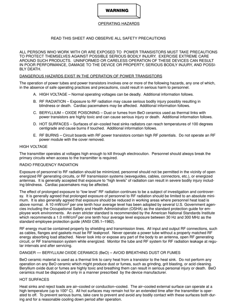
ALL PERSONS WHO WORK WITH OR ARE EXPOSED TO POWER TUBES, POWER
TRANSISTORS, OR EQUIPMENT THAT UTILIZES SUCH DEVICES MUST TAKE PRECAUTIONS
TO PROTECT THEMSELVES AGAINST POSSIBLE SERIOUS BODILY INJURY. EXERCISE
EXTREME CARE AROUND SUCH PRODUCTS. UNINFORMED OR CARELESS OPERATION OF
THESE DEVICES CAN RESULT INPOOR PERFORMANCE, DAMAGE TO THEDEVICE OR
PROPERTY, SERIOUS BODILY INJURY, AND POSSIBLY DEATH!!
DANGEROUS HAZARDS EXIST INTHEOPERATION OFPOWER TUBES AND
POWER TRANSISTORS
The operation of power tubes and power transistors involves one or more of the following hazards, any
one of which, in the absence of safe operating practices and precautions, could result in serious harm to
personnel.
A. HIGH VOLTAGE - Normal operating voltages can be deadly. Additional information
follows.
B. RF RADIATION - Exposure to RF radiation may cause serious bodily injury possibly
resulting in Blindness or death. Cardiac pacemakers may be affected. Additional information
follows.
C. HOT SURFACES - Surfaces of air-cooled radiators and other parts of tubes can reach
temperatures of several hundred degrees centigrade and cause serious burns if touched.
Additional information follows.
D. RF BURNS - Circuit boards with RF power transistors contain high RF potentials. Do not
operate an RF power module with the cover removed.

vi
©2020 Broadcast Electronics
HIGH VOLTAGE
Many power circuits operate at voltages high enough to kill through electrocution. Personnel should
always break the primary AC Power when accessing the inside of the transmitter.
RADIO FREQUENCY RADIATION
Exposure of personnel to RF radiation should be minimized, personnel should not be permitted in the
vicinity of open energized RF generating circuits, or RF transmission systems (waveguides, cables,
connectors, etc.), or energized antennas. It is generally accepted that exposure to “high levels” of
radiation can result in severe bodily injury including blindness. Cardiac pacemakers may be affected.
The effect of prolonged exposure to “low level” RF radiation continues to be a subject of investigation and
controversy. It is generally agreed that prolonged exposure of personnel to RF radiation should be limited
to an absolute minimum. It is also generally agreed that exposure should be reduced in working areas
where personnel heat load is above normal. A 10 mW/cm2per one tenth hour average level has been
adopted by several U.S. Government agencies including the Occupational Safety and Health
Administration (OSHA) as the standard protection guide for employee work environments. An even
stricter standard is recommended by the American National Standards Institute which recommends a 1.0
mW/cm2 per one tenth hour average level exposure between 30 Hz and 300 MHz as the standard
employee protection guide (ANSI C95.1-1982).
RF energy must be contained properly by shielding and transmission lines. All input and output RF
connections, such as cables, flanges and gaskets must be RF leak proof. Never operate a power tube
without a properly matched RF energy absorbing load attached. Never look into or expose any part of the
body to an antenna or open RF generating tube or circuit or RF transmission system while energized.
Monitor the tube and RF system for RF radiation leakage at regular intervals and after servicing.
HOT SURFACES
The power components in the transmitter are cooled by forced-air and natural convection. When
handling any components of the transmitter after it has been in operation, caution must always be taken
to ensure that the component is cool enough to handle without injury.
RF Exposure Safety Distance Warning
RF Exposure Limits for Canada, according to IC regulation: setting to the maximum of the output power of
the apparatus, to guarantee the limits of exposure declared within this document, it is necessary that the
antenna gain used with this device should be 0dBi or less and all persons should maintain a minimum
separation distance of 1119.13 cm for general uncontrolled exposure and general controlled exposure.
Limites d’exposition RF: en réglant au maximum de la puissance de sortie de l’appareil, afin de garantir les
limites d’exposition déclarées dans ce document, il est nécessaire que le gain d’antenne utilisé avec cet
appareil doit être de 0 dBi ou moins et toutes les personnes doivent conserver une distance de
séparation minimale de 1119.13cm pour les expositions générales non contrôlées et les expositions
générales contrôlées.

vii
©2020 Broadcast Electronics
Table of Contents
Default Operation ....................................................................................................................12
Broadcast Electronics-Interface active stub.............................................................................12
GPIO Remote Station Interface................................................................................................13
AC Connection .........................................................................................................................14
Turn on AC ...............................................................................................................................15
Set Time and Date....................................................................................................................15
Frequency ................................................................................................................................16
100% peak modulation ............................................................................................................17
Power set point........................................................................................................................17
Primary Audio Source ..............................................................................................................18
Turn RF Transmission On .........................................................................................................23
Additional Program Services ....................................................................................................24
Ethernet/IP Network................................................................................................................26
Password..................................................................................................................................29
Stereo Generation and Stereo Pilot Injection..........................................................................30
Pre-Emphasis ...........................................................................................................................31
Tuning Digital Mode RF Amplifier Linearity .............................................................................32
Secondary Audio and Silence Timeout ....................................................................................33
GPIO .........................................................................................................................................36
BE INTERFACE ..........................................................................................................................38
ETHERNET ................................................................................................................................38
COM IN.....................................................................................................................................38
COM OUT .................................................................................................................................38
AES ...........................................................................................................................................38
LEFT and RIGHT ........................................................................................................................39
COMP .......................................................................................................................................39
SCA1 and SCA2 .........................................................................................................................39
19kHz OUT ...............................................................................................................................39
PA RF IN....................................................................................................................................39
10MHz IN .................................................................................................................................39
1 PPS IN....................................................................................................................................39
EXC RF OUT ..............................................................................................................................40
RDS...........................................................................................................................................40
RF OUT .....................................................................................................................................40
RF SAMPLE ...............................................................................................................................40
Ground .....................................................................................................................................40
AC Input & Power Switch .........................................................................................................40
AUDIO ......................................................................................................................................41
EXC DRV ...................................................................................................................................42
CNTL .........................................................................................................................................42
PA.............................................................................................................................................42
PS .............................................................................................................................................42
VSWR .......................................................................................................................................42

viii
©2020 Broadcast Electronics
FAILSAFE...................................................................................................................................42
TRANSMITTER CONTROL CENTER ............................................................................................43
Login Profiles - Basic Web Page ...............................................................................................57
RDS and FSK Setup ...................................................................................................................60
Audio Delay Setup....................................................................................................................61
Login Profiles – GUI Web Page.................................................................................................63
Navigation................................................................................................................................64
Power Amplifier .......................................................................................................................66
Combiner .................................................................................................................................67
Exciter ......................................................................................................................................69
Input/Output............................................................................................................................70
Audio........................................................................................................................................71
Logs ..........................................................................................................................................71
Other Features - VSWR vs Reflected Power ............................................................................72
Authentication .........................................................................................................................74
Objects .....................................................................................................................................74
Emergency Control Mode ........................................................................................................75
Standby System Control and Exciter........................................................................................75
Event Log..................................................................................................................................76
Standby ....................................................................................................................................76
Failsafe .....................................................................................................................................76
Mute ........................................................................................................................................77
Internal Exciter Diagnostics......................................................................................................77
Power Amplifier Diagnostics ....................................................................................................77
Clean Air Filters and Check Fans ..............................................................................................79
Low Voltage Power Supply ......................................................................................................79
Combiner Fan...........................................................................................................................79
Main/Add-on Fan.....................................................................................................................80
Front Panel Board ....................................................................................................................80
Power Amplifier .......................................................................................................................80
Add-on PA Controller ...............................................................................................................81
System Controller and Exciter..................................................................................................81

ix
©2020 Broadcast Electronics
Figures
Figure 1 – STXe Front Panel User Interface ..........................................................................................11
Figure 2 – STXe Rear GPIO & Interface.................................................................................................11
Figure 3 – BE Activation Stub ...............................................................................................................13
Figure 4 – GPIO Fail Safe Jumper..........................................................................................................13
Figure 5 – D-Sub Shell Whole and Nuts................................................................................................14
Figure 6 – AC Input ...............................................................................................................................14
Figure 7 – Feature / Connector Location REAR ....................................................................................35
Figure 8 – Control and Feature Locations - FRONT ..............................................................................41
Figure 9 – Transmitter Control Center .................................................................................................43
Figure 10 – Transmitter Control Center Menus Sheet 1 ......................................................................47
Figure 11 – Transmitter Control Center Menus Sheet 2 ......................................................................49
Figure 12 – ............................................................................................................................................52
Figure 13 – ............................................................................................................................................54
Figure 14 – Web Interface Main Page ..................................................................................................57
Figure 15 – Web Interface Authentication ...........................................................................................58
Figure 16 – Expanded View on Main Page ...........................................................................................58
Figure 17 – Web Interface PA Status Page ...........................................................................................59
Figure 18 – Web Interface Events Page................................................................................................59
Figure 20 – RDS Setup Page..................................................................................................................60
Figure 21 – Audio Delay Web Interface................................................................................................61
Figure 22 – Link from Basic Web Page to GUI Main Page ....................................................................62
Figure 23 - GUI Pointer Icons................................................................................................................63
Figure 24 – Login Selection...................................................................................................................63
Figure 25 – Login Process .....................................................................................................................63
Figure 26 – Profile Logged Out .............................................................................................................64
Figure 27 – Navigation Bar ...................................................................................................................64
Figure 28 – Main Screen .......................................................................................................................65
Tables
Table 2 – GPIO Pins...............................................................................................................................36
Table 3 – BEI Pins..................................................................................................................................38
Table 4 – Main Page and Common Features........................................................................................65
Table 5 – Power Amplifier Display Features.........................................................................................67
Table 6 – Combiner Display Features ...................................................................................................68
Table 7 – Exciter Page Features............................................................................................................69
Table 8 – Audio Page Features .............................................................................................................71
Table 9 – Exciter Diagnostics Details ....................................................................................................77
Table 10 – PA Diagnostics Details.........................................................................................................77

11
©2020 Broadcast Electronics
Overview
The circled areas shown in the front and rear views below will be referenced in the following Section
“Installation and Initial Set Up”. If you are not currently familiar with the STX Series, please refer to the
detailed information provided in Sections 4 & 5 of this manual for addition installation and product
information.
Figure 1 – STX 3 Front Panel User Interface
Figure 2 – STXe Series Rear GPIO & Interface

12
©2020 Broadcast Electronics
Installation & Initial Set Up
Default Operation
In the absence of specific customer settings or when a reset to factory defaults command is
issued on the front panel user interface, the following default settings are used:
1. Transmitter RF On/Off – Off
2. Frequency – 98.1 MHz
3. Operating Mode – FM Only
4. FM-only Power Set point – 3000W
5. Digital-only Power Set point – 1020W
6. FM+Digital Power Set point – 2310W
7. Sideband power level – -20 dBc
8. Digital PAV – 44.0V
9. Emergency Output Power – 0 W (disabled)
10. 100% Modulation – 75 kHz
11. Pre-emphasis – None
12. Pilot Injection – On, 10%
13. Mono/Stereo Mode - Stereo
14. Audio Input – Composite
15. AES – -2dBFS input level
16. AES Stereo injection – 100%
17. Analog L – -2.5 dB input gain
18. Analog R – -2.5 dB input gain
19. Analog L/R Stereo injection – 100%
20. Composite – +8.0 dB input gain
21. SCA1
oOff
o-12.0 dB input gain
22. SCA2
oOff
o-12.0 dB input gain
23. RDS – Off, -12.0 dB input gain
oOff
o-12.0 dB input gain
24. Real Time Clock – shipped with Quincy, IL time, factory reset does not affect this
Note: The internal real time clock is likely to have stopped keeping time and reset to
2000-01-01 00:00:00 during shipping or any other time when the system is unpowered
for days.
Broadcast Electronics-Interface active stub
The activation stub is required for operation. If the stub was removed for shipment, connect it
to the BE Interface located just below the GPIO connector as shown and secure the two
jackscrews with a small flat screwdriver.

13
©2020 Broadcast Electronics
Figure 3 – BE Activation Stub
If the STX 3 was purchased with other system options such as the VPe signal generator that
utilize this connection, save this stub for servicing or bench testing.
GPIO Remote Station Interface
For General Purpose Input/Output wiring connections, use the supplied 37PIN female D-
Subminiature connector 418-0283 and it’s D-Sub Shell 417-0284 for this solder pot connector.
Refer to Table 2 located in section 4.1.1-GPIO, for the pin out information for connection to a
sites remote control system.
All installations require unmute/failsafe to be activated at a minimum. If this is the only site
requirements, follow these steps for setup.
1. Connect unmute/failsafe pin 2 (left connection in figure) to ground pin 19 (right connection
in figure) through a failsafe relay. If no transmitter failsafe circuitry exists, or for bench
testing, substitute a wire jumper as shown in Figure 2.
Figure 4 – GPIO Fail Safe Jumper
2. Insert the connector on one of the shell halves.
3. Place the other shell half on top and set the nuts in place as indicated in the figure.

14
©2020 Broadcast Electronics
Figure 5 – D-Sub Shell Whole and Nuts
4. Plug the assembly on the GPIO connection and secure the screws.
AC Connection
ENSURE ACMAIN ISDISCONNECTED AND LOCKED OUT BEFORE INTERACTING
WITH ANY ACCONNECTIONS
1. Insert AC wiring into the rear connector as shown in Figure 6
Figure 6 – AC Input

15
©2020 Broadcast Electronics
Turn on AC
1. Unlock AC main breaker on the service line and turn the STX switch to the on position.
Set Time and Date
The internal real time clock holds the current time and date for use in the event log. This is a
rudimentary device that supports 24-hour format and does not adjust for daylight saving. If
installing during summer in a daylight saving region, following standard non-daylight time is
recommended instead (the internal real time clock does not automatically compensate for any
daylight saving).
1. From the main screen on the transmitter control center on the front panel of the main
assembly, press up or down to navigate to the Date and Time menu. Press enter to continue.
< 2000-01-01 >
TRAN SM ITTER CON TROL CENTER
00:00:00
2. Press up or down to select the time editing screen.
SET CLOCK
TRAN SM ITTER CON TROL CENTER
TIM E
3. Set the local (24 hour non-daylight saving) time. Press left or right to move the cursor and
press up or down to increment or decrement the number.
TIM E-> 00:00:00
TRAN SM ITTER CON TROL CENTER
^
4. Press enter when finished editing for the setting to take effect in the system, save, and start
keeping time.
5. Enter the date and time menu again. Press up or down to navigate to the date editing
screen.

16
©2020 Broadcast Electronics
SET CLOCK
TRAN SM ITTER CON TROL CENTER
DATE
6. Set the current date. Press left or right to move the cursor and press up or down to
increment or decrement the number.
DATE-> 2000-01-01
TRAN SM ITTER CON TROL CENTER
^
7. Press enter when finished editing for the setting to take effect in the system, save, and keep
time.
Frequency
STX 3 is built around frequency agile exciter and PA hardware. The frequency can be changed
directly from the front panel – no hardware modifications or tuning procedure is required when
the carrier frequency is changed.
If the STX RF output is on (“TX ON”) when the frequency is changed, the system will momentarily
turn the RF output off, change the frequency, and immediately turn RF back on again with the
new frequency
1. From the main screen on the transmitter control center on the front panel of the main
assembly, press up or down to navigate to the FREQUENCY menu. Press enter to continue.
< FREQU EN CY >
TRAN SM ITTER CON TROL CENTER
98.10M Hz
2. Press left or right to move the cursor between frequency digits. Press up or down on each
digit to increment or decrement the number.
FREQ-> 98.10M Hz
TRAN SM ITTER CON TROL CENTER
^
3. Press enter when finished editing for the frequency change to take effect.

17
©2020 Broadcast Electronics
100% peak modulation
The STX & STXe defaults to 100% modulation being +/- 75 kHz. This section only applies if the STX
is being used in an installation where 100% modulation is not +/- 75 kHz.
1. From the main screen on the transmitter control center on the front panel of the main
assembly, press up or down to navigate to the AUDIO LEVEL menu. Press enter to continue.
< AU D I O LEV EL >
TRAN SM ITTER CON TROL CENTER
2. Press up or down to select DEV, the FM deviation control setting. Press enter to continue.
AU DI O LEVEL
TRAN SM ITTER CON TROL CENTER
DEV-> 075kHz
3. Press left or right to move the cursor between frequency digits. Press up or down on each
digit to increment or decrement the number. This change takes effect immediately in the
system without saving the setting to allow for active tuning.
DEV-> 075kHz
TRAN SM ITTER CON TROL CENTER
0.0% ^
4. Press enter when finished editing to save the deviation control setting.
Power set point
1. From the main screen on the transmitter control center on the front panel of the main
assembly, press up or down to navigate to the PWR SET menu. Press enter to continue.
<PW R SET=1000W>
TRAN SM ITTER CON TROL CENTER
1000W RFL= 6
2. Press up or down to select the power set point for the FM operation mode, which should
display as active. Note that digital, FM+digital, and hybrid HD sideband settings require an
optional VPe system. Press enter to continue.

18
©2020 Broadcast Electronics
POW ER
TRAN SM ITTER CON TROL CENTER
FM ACTI V E
3. Press left or right to move the cursor between digits. Press up or down on each digit to
increment or decrement the number. Current output forward power measurements are
displayed in the lower left of the screen.
FM -> 1015W
TRAN SM ITTER CON TROL CENTER
1000W ^
4. Press enter when finished editing for the new power set point to take effect.
Primary Audio Source
The STXe provides built-in injection of one primary audio source: AES, Composite, or Analog L/R.
Secondary audio sources SCA1, SCA2, and RDS can be enabled and used in any on/off combination with
these primary audio sources.
AES
The STXe supports standard AES audio as well as 192 kHz Composite over AES. The 192 kHz
Composite over AES operates with various brand name systems including Wheatstone, Omnia
and Orban audio processors.
To operate Composite over AES, follow the steps below, but select “AES COMP” rather than
“AES” as the input
1. Connect an XLR cable from the desired AES audio source.
2. From the main screen on the transmitter control center on the front panel of the main
assembly, press up or down to navigate to the AUDIO INPUT menu. Press enter to
continue.
< AUDIO INPUT >
TRAN SM ITTER CON TROL CENTER
COM POSITE
3. Press up or down to select AES as the primary audio source. Press enter to continue.
AUD IN-> AES
TRAN SM ITTER CON TROL CENTER
^

19
©2020 Broadcast Electronics
4. The screen will display the injection percentage allocated to AES. This setting allows the
customer to budget the modulation when supplementary services are present. Leave
this at 100% if there are no supplementary services in use. If supplementary services are
present, set the total modulation percentage associated with AES. This can be adjusted
from 70% to 100%. Use the left and right arrows to move the cursor. Press up or down
buttons for each digit to increment or decrement the number.
100.0% AES
TRAN SM ITTER CON TROL CENTER
^
5. Press enter when finished editing for the setting to take effect in the system and save.
6. AES audio levels are expressed in terms relative to Full Scale of the digital signal path
selected.
7. From the main screen on the transmitter control center on the front panel of the main
assembly, press up or down to navigate to the AUDIO LEVEL menu. Press enter to
continue.
< AU D I O LEV EL >
TRAN SM ITTER CONTROL CEN TER
8. Press up or down to select “AES”. Press enter to continue.
AU DI O LEVEL
TRAN SM ITTER CONTROL CEN TER
AES-> -02.0d BFS
9. The display will show the current peak modulation attributable to the AES input. The
level can be adjusted by changing the associated dBFS setting. This has a range of -28.0
dBFS to +0.0 dBFS in 0.1 dB steps. This represents the AES level that will generate the
percentage modulation shown on the screen
10. Press left or right to move the cursor. Press up or down on each digit to increment or
decrement the number and take effect in the system. This has immediate effect. Do this
until the displayed left channel peak hold is the desired value – typically 100%.
AES-> -02.0d BFS
TRAN SM ITTER CONTROL CEN TER
10% ^
11. Press enter when finished editing to exit the sub-menu.
Table of contents
Other Broadcast Electronics Transmitter manuals

Broadcast Electronics
Broadcast Electronics FX-50 User manual

Broadcast Electronics
Broadcast Electronics FM-10T User manual

Broadcast Electronics
Broadcast Electronics PNP 1000 User manual

Broadcast Electronics
Broadcast Electronics AM-500A User manual

Broadcast Electronics
Broadcast Electronics AM-500A 500 WATT User manual

Broadcast Electronics
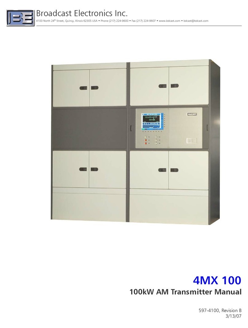
Broadcast Electronics 4MX 100 User manual

Broadcast Electronics
Broadcast Electronics AM-6A User manual

Broadcast Electronics
Broadcast Electronics AM-2.5E User manual

Broadcast Electronics
Broadcast Electronics FM-5T User manual