Akura ATW-GA2929 User manual

Scart Style Wireless
Audio/Video Sender
ATW-GA2929
Instruction Manual
Customer Help Link:01422 26 33 13
Website:www.ekey.co.uk


The lightning flashwith arrowhead symbol,within an equilateraltriangle,
is intended toalert the userto the presenceof un-insulated "angerous
Voltage" within theproducts enclosure thatmay be ofsufficient magnitude
to constitute arisk of electricshock to thepersons.
The exclamation pointwithin an equilateraltriangle is intendto alert the
user to thepresence of importantoperating and maintenance(servicing)
instructions in theliterature accompanying theappliance.
Correct disposal ofthis Product
(WasteElectrical & ElectronicEquipment (WEEE)
The crossed out"Wheelie bin" isintended to showthat this appliancemust
not be placedwith ordinary householdwaste at theend of itsuseful life.To
prevent possible harmto the environmentor human healthfrom
uncontrolled waste disposal,please keep separatefrom other household
waste and recycleit responsibly topromote the sustainablereuse of
material resources.
Household users shouldcontact either theretailer where youpurchased the
product, or theirlocal government office for detailsof where andhow you
can take thisitem for environmentallysafe re-cycling.
Business users shouldcontact their supplierand check theterms and
conditions of thepurchase contract.This product mustnot be mixedwith
other commercial wastesfor disposal
Safety Instructions.
Care and Maintainance
Keep all itsparts and accessoriesout of thereach of youngchildren.
Keep dry. Precipitation, humidity, and liquids,contain minerals thatwill corrode
electronic circuits.
Do not handlethe mains adaptorswith wet hands.
Do not operatein areas ofhigh temperature.This may damageelectronic components,
the case andpossibly cause frequencydrift.
Do not drop,knock, or shakeit. Rough handlingcan break internalcircuit boards.
If you wishto clean theseitems, do notuse chemical orpetrol based cleaningfluids.
Disconnect the Mainsadaptors and cleanwith a dampcloth.
Operate this productusing only theMains adaptors supplied.These mustonly be used
on a 220-240VAC 50 Hz supply. Do NOTuse alternative supplies.
If the adaptorsfail to work,do not attemptto open thecase, there areno user
serviceable parts inside.Opening the caseswill invalidate yourwarranty 1

Product Layout
Connections
Fig. 1
Receiver/Transmitter
Fig. 2
2
3
1
4
5
678
67
8
Product Layout
Transmitter/Receiver(Fig. 2)
1. Power ONLED
2. Power ON/ OFF switch
3. Scart plug
4. IR Sensor
5. IR Mouse
6. IR Sensor/ Mouse socket
7. PowerAdapter Socket
8. Channel SelectionSwitch (Select thechannel by slidingthe slide switchto the channel
number you want.Note: Must select the same channel both on transmitter and
receiver)
2

Setting up
1
Transmitter
Setting up the Transmitter
A/V Connection
1.1
Fig. 3
Connect the Transmitter to your AV source, eg Freeview box,VCR or
DVD player
VIDEO
OUT RF OUT
1.2Power Supply
Fig. 4
2
Transmitter
1
3
3

Setting up the Receiver
2
2.1 Connect the receiver module to the Tv scart socket
1.3Fine Tuning
A/V Component
Transmitter
Front
Fig. 5
OUT
A/V Connection -for TV with A/V Input Jacks
IN
TV
Fig. 6
Receiver
4

2.2 Power Supply
Fig. 7
2
1
3
Receiver
2.3Remote control of the transmitter from your receiver
Front
Fig. 8
TV
Receiver
IN
What You Get
Transmitter withIR Mouse
Receiver with IR Sensor
Two Power Adapters
This User's Manual
Note: The transmitter and receiver look very alike. You can find
"Transmitter" and"Receiver" on the top of the units. See Fig. 1.
5

Setting up
Before you make the connections:
Set the channelswitches on theback of thetransmitter and receiverto the same
channel.
Depending on the type of TVyou own and the component A/V system (VCR,
DVD player,etc.), connection methods will be different.Werecommend you
refer to the connected A/Vcomponent's user's manual for details, then make
connections according to the following steps.
1
1.1
Setting up the Transmitter
Connect the Transmitter to the A/V Equipment
A/V Connection
Simply plug the video transmitter into the SCART outputof a VCR.DVD
player. See Fig3.
Power Supply
1. Plug oneend of theprovided power adapterinto a walloutlet and theother
end into the rear of the transmitter. See Fig. 4.
2. Turn on the transmitter. TheLED on the front of the unit should light up.
I/R Relay connection
Plug the transmitter in theA/V equipment,and position the IR mouse
so that it faces the IR sensor window ofthe AV source apparatus.
See Fig. 5.
2
2.1
Setting up the Reciver
Connect the Receiver to a TV
Plug the transmitter in the TV. See Fig.6.
2.2 Power Supply
1. Plug oneend of theprovided power adapterinto a walloutlet and theother
end into the rear of the receiver. See Fig. 7.
2. Turn on the transmitter. TheLED on the front of the unit should light up.
6

Trouble Shooting Guide
If you are experiencing trouble, please refer to the table next before calling the
Customer Help desk.
Testing the system before Final installation.
It is wiseto set upthe system inthe same roombefore installing thereceiver in
another location.
This ensures thatthe system isworking before youinstall in anotherroom.
The TVsignal is carried on a Super UHF carrier (2.4 Ghz) Thissignal may not
penetrate solid brickwalls.
2.3 Remote Control ( Changes the channel of your signal source)
1. Plug the receiver in the TV, and adjust the receiver by rotating orientations
until you get the best reception.
2. Position the IR mouse so that your remote control signal can strike the
front of the IR mouse. See Fig.8.
3. To use your remote control, point it at the front of the IR mouse and
operate it as you normally would.
7

Symptom Possible Cause Remedy
Leds not lit on
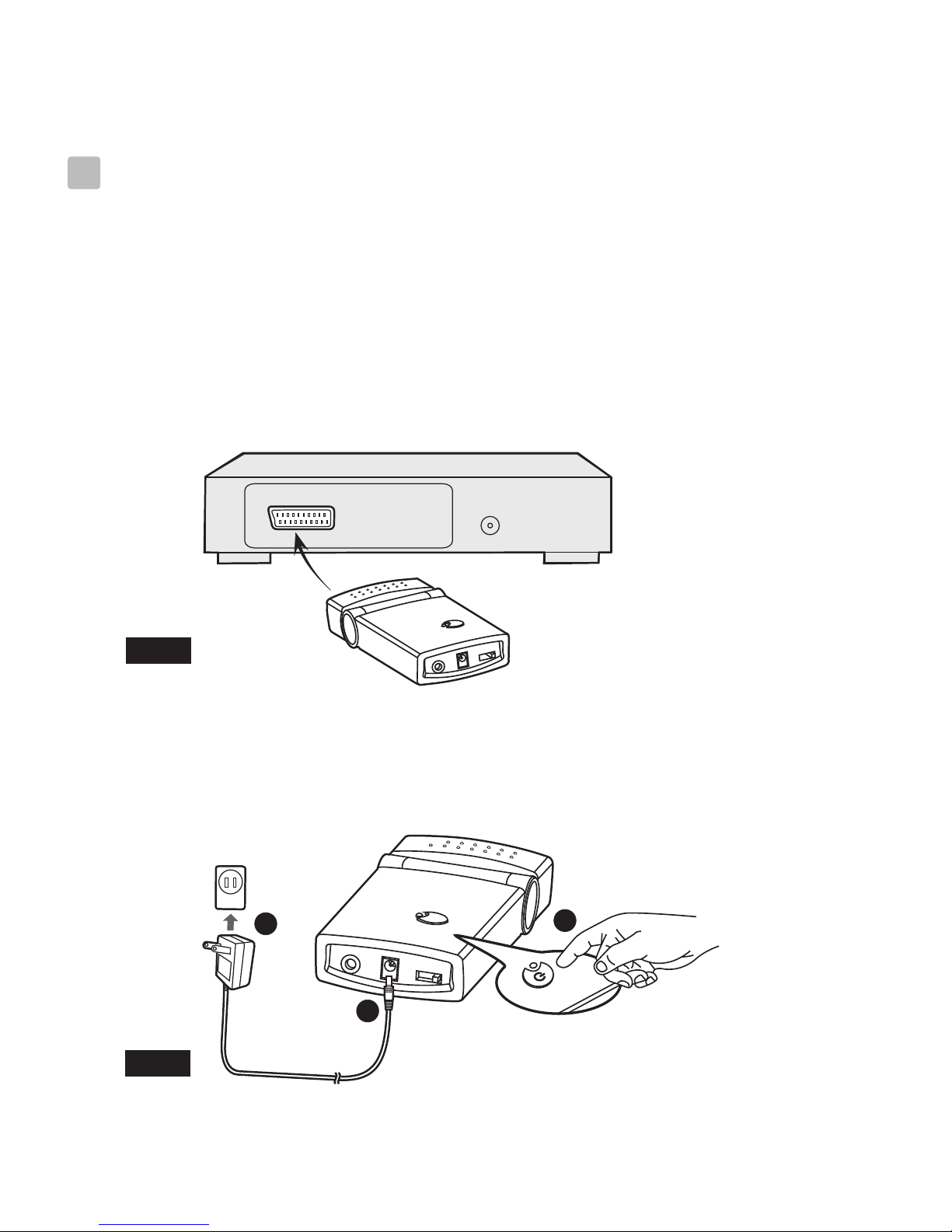
Sender or receiver Power adaptors not connected
Ensure both power adaptors are
connected and the sender and receiver are
turned on
Receiver out of range of the
signal.
"90 feet max"in clear conditions
( no obstructions)
Receiver not switched to AV
Input
Receiver aerial not aligned to
sender aerial.
Rotate the receiver/aerial for the best
signal.
Signal path too long. Reduce the signal path.
Horizontal signal paths are more difficult,
due to more solid materials being used.
Change the switch selection on BOTH
sender and receiver. This may stop the
problem.
Remote sender (Mouse) not being
activated.
Ensure the remote control actually works
on the sender box before installation.
Sender remote control window
not being activated with the I/R
sender
Ensure the sender can see the remote I/R
sender.
Batteries in remote control
exhausted Change batteries in remote control
Leds lit but no
picture or sound on
the receiver.
Poor signal
reception
Too much signal loss due to
building construction Vertical signal paths have less lo ss due to
lighter materials being used
No Remote control
functions.
Interference bars on
screen
Another signal source interfering.
Computer WiFi links operating
near the receiver will cause
interference, or Later Baby Alarm
monitors
Move the WiFi link away from the
receiver module.
Sender and receiver not matched Ensure sender and receiver switches are
set to same number.
See above, test in the same room before
installation
Select AV or SCART input on the
receiving Tv. In most cases the TV will
not switch automatically
8

If you are still having difficultyplease call the Technical help line. Ring 01422
263313 (Normal rates apply).
Opening hours Mon-Fri 8 am 8pm. Sat 9 am 4pm. Sun 11am 4pm “Bank holidays
as Sun”
Or try our website :- www.ekey.co.uk (24Hr)
Specifications subject tochange without notice
Transmitter/Receiver
A/V Transmit Frequency 2.4 GHz
Remote Control Freuency 433.92 MHz
AV Signal Range 30 meters (90 feet) clear line of sight
Remote Control Signal Range 20 meters (60 feet) clear line of sight
Antenna Built-in omni-directional antenna
Channel 4 selectable channels
A/V mod/demod. method FM
Audio Stereo audio input and output
Video Composite video input and output
Dimensions 13.7 (W) x 5.5 (H) x 2 (D) cm
(5.4 x 2.2 x 0.8 inches) each for transmitter/receiver
Weight 90g / 97g transmitter/receiver
Power DC 9V, 300mA
Operating temperature 0 ~ 40 (32 ~ 104 )
0678
Specifications
9

Aug,2007 408-000444-00
Table of contents