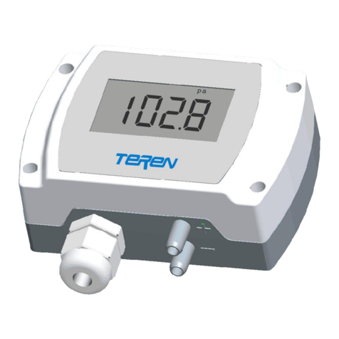
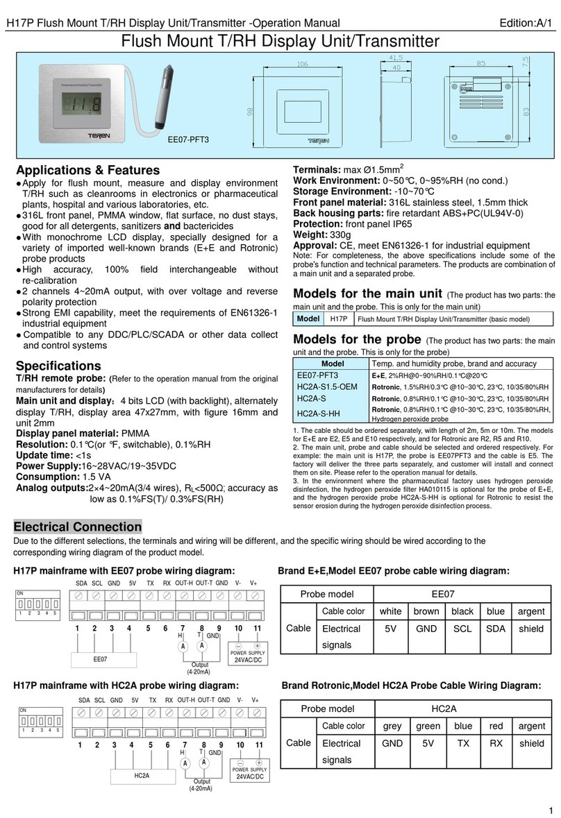
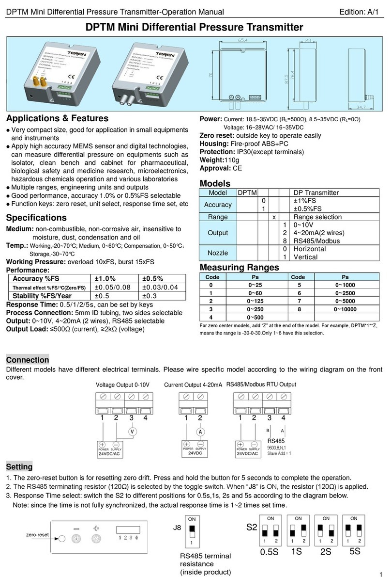
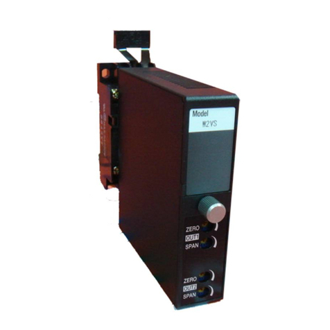
TEREN DPTR User manual

DPTR Rail Mount Differential Pressure Transmitter-Operation Manual Edition:A/3
1
DPTR Rail Mount Differential Pressure Transmitter
Applications & Features
Mount on standard 35mm DIN rail, small enough for
compact installation in equipments and instruments
Apply high accuracy MEMS sensor and digital technologies,
can measure differential pressure on equipment such as
isolators and clean benches for pharmaceutical production,
biological and medicine research, microelectronics,
hazardous chemicals operations, and general laboratories
Multiple ranges, engineering units and outputs
Good performance, accuracy 1.0% or 0.5%FS selectable
Function keys: zero reset, unit select, response time set,
etc
Specifications
Medium: non-combustible, non-corrosive air, insensitive to
moisture, dust, condensation and oil
Temp.: Working,-20~70°C; Medium, 0~60°C; Compensation, 0~50°C
Storage: -30~70°C
Working Pressure: overload 10xFS, burst 15xFS
Performance:
Accuracy %FS
±1.0%
±0.5%
Thermal
effect %FS/°C(Zero/FS)
±0.05/0.08
±0.03/0.04
Stability %FS/Year
±0.5
±0.3
Response Time: 0.5/1/2/5s, can be set by keys
Process Connection: 5mm ID tubing
Output: 0~10V, 4~20mA (2 wires), RS485 selectable
Output Load: ≤500Ω (current), ≥2kΩ (voltage)
Power: Current: 18.5~35VDC (RL=500Ω)8.5~35VDC (RL=0Ω)
Voltage: 16~28VAC/ 16~35VDC
Zero reset: outside key to operate easily
Materials: Fire-proof ABS+PC
Protection: IP30
Weight: 110g
Approval: CE
Models
Model
DPTR
Rail Mount DP Transmitter
Accuracy
0
±1%FS
1
±0.5%FS
Range
x
Range selection(See table)
Output
1
0~10V
2
4~20mA(2 wires)
8
RS485/Modbus
Measuring ranges
Note: For zero center models, add “Z” at the end of the model. For example,
DPTR*1*Z, means the range is -30-0-30.Only 1~6 have this selection.
Connection
Different models have different electrical terminals. Please wire specific model according to the wiring diagram on the front
cover.
Setting
1. The zero-reset button is for resetting zero drift. Press and hold the button for 5 seconds to complete the operation.
2. The RS485 terminating resistor (120Ω) is selected by the toggle switch. When “J8” is ON, the resistor (120Ω) is applied.
3. Response Time select: switch the S2 to different positions for 0.5s,1s, 2s and 5s according to the diagram below.
Note: since the time is not fully synchronized, the actual response time is 1~2 times set time.
Code
Pa
Code
Pa
0
0~25
5
0~1000
1
0~60
6
0~2500
2
0~125
7
0~5000
3
0~250
8
0~10000
4
0~500
RS485
9600,8,N,1
Slave Add.= 1
3 4
A
1 2
POWER SUPPLY
B
24VDC/AC
V
3 4
POWER SUPPLY
24VDC
A
3 4
POWER SUPPLY
1 2
Current Output 4-20mA
Voltage Output 0-10V RS485/Modbus RTU Output
24VDC/AC
ON
12
ON
12
ON
12
ON
12
0.5S 1S 2S 5S
S2
RS485 terminal
resistance
(inside product)
ON
1
J8
zero-reset

DPTR Rail Mount Differential Pressure Transmitter-Operation Manual Edition:A/3
2
Installation:
Figure 1 Figure 2 Figure 3 Figure 4
● Install into the DIN rail: it is recommended that the pressure ports to be installed vertically downwards, as shown in above
figures. As Figure 1 and 2, insert the transmitter’s upper hook into DIN-rail, then buckle the lower white plastic hook into DIN-
rail, as Figure 3. The plastic hook can be pulled down to help.
● Pressure connection: connect the tube to the two pressure ports correctly, making sure to air-tighten to prevent leakage.
● Electrical connection: As figure 4, unplug the terminals of the transmitter and wire correctly, then plug back.
Zero reset & Calibration
● Due to different environment and sensor characteristics, after long term of using, the sensor’s accuracy maybe drift. The
transmitter should be zero reset after initial installed to meet the specified accuracy. It is better to be “zero reset” after the initial
7 days continuous working. Usually it need to be zero reset periodically in every 6-12 months’ working.
●Zero reset: keep the high (+) and low (-) pressure ports unconnected in stable air, or directly connect the two, press the button
“ZERO” for 5s. It means to remove the zero drift of the transmitter in order to improve the accuracy. It is recommended that
this operation to be done periodically.
●Initial zero reset: when initial power on, it should be zero reset after fully warm-up and stable, to meet the specified accuracy.
●Long term zero drift & reset: It may have long term zero drift after continuous working; customers can reset it periodically.
●Re-calibration & zero reset: when re-calibration needed, zero reset should be done first. A qualified standard manometer is
needed for re-calibration operation.
Attention
It should be power OFF during installing and wiring. When using 24VAC, it is strongly recommended to power the unit with
independent transformer. If sharing a 24VAC transformer with other equipments such as controllers, transmitters or actuators,
please make sure the terminals 24V and GND are connected correctly. Otherwise, it may reduce serious damages.
Warranty
● It has limited warranty for eighteen (18) months after the production date.
● It does not extend to any unit that has been subjected to misuse or accident.
● It is, in any event, strictly limited to the replacement or repair of the product itself.
Shenzhen TEREN Control Technology Co. Ltd.
Add: 3F, 2nd Industrial Zone, Nankeng, Longgang
District, Shenzhen,Guangdong,P.R.CHINA
Tel: 0755-23935155 Fax: 0755-23935156
web: www.teren.com.cn
TEREN website Alibaba shop
Table of contents
Other TEREN Transmitter manuals
