4
SS 16.1 Installation and Operation Manual
DESCRIPTION
PRODUCT DESCRIPTION
The 16x1 passively switches or routes any one of 16 stereo inputs to one stereo out-
put or vise-versa through gold contact relays. The passive nature of the switching
allows for any input level and impedance to be used. Inputs may be balanced or
unbalanced, while output levels, impedance, distortion, noise and balancing will
match that of the selected input. In addition to their normal use with audio signals,
the 16x1 can also be used to switch digital signals and telephone lines. Control is via
front panel switches, contact closures, open collector status and/or multi-drop RS-
232 port. Removable screw terminals are provided for all audio connections.
The 16 x 1 has several unique features. The Power-Up feature allows the user to
select which of any source is active at power up, including the last source selected.
Audio mute allows the user to turn off the audio output when activated. The Enable
switch provides a safety lock to the front panel source selection switches. An Audio
Activity Monitor LED with remote status. A Step Input provides a means of step-
ping through each source, including MOH Station Selection. A Serial Port allows
communication and operation from a computer’s serial port. A 2 x 1 bypass output
switcher is provided to allow switching between the 16 x 1 and an external source.
Source number one is configured by default to route audio to the output in the case
of loss of power to the unit. Non-selected sources are terminated with 10K Ω, load
resistors.
APPLICATIONS
Some of the applications of the 16 x 1 include: Studio selection and routing; Audio
processing selection; Exciter input selection; Remote broadcast input selection; STL
source selection; Automation source selection; Multiple station Music On-Hold
and/or PA switching; EAS audio switching; ISDN or Phone hybrid feed selection;
IFB selection; Satellite audio channel switching and console monitor inputs and out-
puts selection.
FRONT PANEL DESCRIPTION
Source Switches:
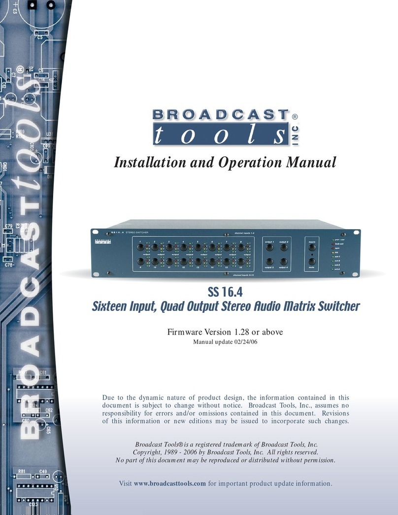
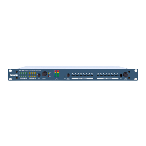
Each switch represents an input to be routed to the switcher’s output. High quality
tactile switches will give the user years of dependable service. Each switch has an
associated LED indicator, which will illuminate when that particular source is rout-
ed to the output. When a source is selected, the previous source will be deselected,
(interlocked). The ENABLE switch, when enabled, must be pressed and held in
order for any of the source switches to function. This function may be bypassed.
The front panel is also equipped with a MUTE switch. This switch, when pressed
in combination with the ENABLE switch, turns off the output.
WEBSITE:
Visit our web site for
product updates and
additional information.
