Broadcom ACPL-355JC-62mmSiC-RM100
3
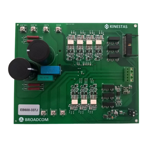
ACPL-355JC Reference Manual 62-mm SiC Module EB1200M62-355JC Evaluation Board
Table of Contents
Chapter 1: Introduction ...................................................................................................................... 5
1.1 Design Features ........................................................................................................................................................6
1.2 Target Applications...................................................................................................................................................6
1.3 Warnings....................................................................................................................................................................7
Chapter 2: System Description ......................................................................................................... 8
2.1 Key Specifications ....................................................................................................................................................8
2.2 Functional Block Diagram........................................................................................................................................8
2.3 Pin Assignment .......................................................................................................................................................11
2.3.1 Power Interface...............................................................................................................................................11
2.3.2 Signal Interface ...............................................................................................................................................11
2.4 Mechanical Data ......................................................................................................................................................12
Chapter 3: Circuit Description ......................................................................................................... 13
3.1 Power Management ................................................................................................................................................13
3.2 Gate Driver Circuit ..................................................................................................................................................17
3.2.1 Gate Driver Circuit: Low-Voltage Side ............................................................................................................18
3.2.2 Gate Driver Circuit: High-Voltage Side ...........................................................................................................20
3.2.3 Protection Features.........................................................................................................................................21
3.2.3.1 OC ........................................................................................................................................................21
3.2.3.2 UVLO ....................................................................................................................................................23
3.3 Measurements .........................................................................................................................................................23
3.3.1 Isolated DC Bus Voltage Measurement (Detachable) ....................................................................................23
3.3.2 Example Test Setup for Switching Current Measurement ..............................................................................25
3.4 Connectors ..............................................................................................................................................................26
3.4.1 Power Connectors for the High-Voltage Side .................................................................................................26
3.4.2 VCC +15V Connector ......................................................................................................................................26
3.4.3 User Interface Connector................................................................................................................................27
3.4.4 Current Measurement Interface Connector ....................................................................................................28
3.4.5 ACPL-736J Sigma-Delta Current Sensing Module .........................................................................................29
3.5 Installation of the EB1200M62-355JC....................................................................................................................31
3.6 Evaluation of the EB1200M62-355JC ....................................................................................................................32
Chapter 4: Typical Switching and Over-Current Protection Characteristics .............................. 33
4.1 Typical Switching Waveforms with WAB300M12BM3 .........................................................................................33
4.2 Typical Switching Losses with WAB300M12BM3 ................................................................................................34
4.3 Typical Over-Current Protection Performance with WAB300M12BM3 ..............................................................36
4.4 Typical Switching Waveforms with FF6MR12KM1...............................................................................................37
4.5 Typical Switching Losses with FF6MR12KM1......................................................................................................40
4.6 Typical Over-Current Protection Performance with FF6MR12KM1....................................................................42

