Broco PRIME-CUT PC/TAC Instruction Manual

TACTICAL CUTTING TORCH KITS
PC/TAC
&
PC/MINI-TAC
OPERATING INSTRUCTIONS
MANUAL
Broco, Inc.
8690 Red Oak St.
Rancho Cucamonga, CA 91730-4819
Tel: 909 483 3222 Fax: 909 483 3233
Toll Free: 800 845 7259
E-mail Broco@Worldnet.att.net
www.brocoinc.com
Aug.’99 ed.

TABLE OF CONTENTS
Chapter 1 GENERAL INFORMATION AND SAFETY
PRECAUTIONS
Section I. INTRODUCTION
1-1. THERMAL BREACHING
1-2. PRIME-CUT TACTICAL TORCH KITS
1-3. WARNINGS
1-4. SAFETY PRECAUTIONS
Section II. EQUIPMENT DESCRIPTION
1-5. PC/TAC TACTICAL CUTTING TORCH SYSTEM
1-6. PC/MINI-TAC COMPACT CUTTING TORCH SYSTEM
Chapter 2 PREPARATION
Section I. SETUP PROCEDURES
2-1. PREPARING THE WORK AREA
2-2. PRE-ASSEMBLY INSPECTION
Section II. PC/TAC ASSEMBLY PROCEDURES
2-3. OXYGEN SYSTEM
2-4. IGNITION SYSTEM
2-4-1. Lightweight Battery
2-4-2. Battery Adapter Clamps
Section III. PC/MINI-TAC ASSEMBLY PROCEDURES
2-5. OXYGEN SYSTEM
2-5-1. Handheld Mode.
2-5-2. Conventional Mode.
2-6. IGNITION SYSTEM
Section IV. ACCESSORIES
2-7. LEATHER SHIELD
2-8. FANNY PACK
2-9. ROD EXTENDER
2-10.RAPIDFIRE CUTTING ROD IGNITORS

Chapter 3 OPERATING INSTRUCTIONS
Section I. INTRODUCTION
3-1. TORCH OPERATION
Section lI. OPERATING PROCEDURES
3-2. ROD INSERTION
3-3. IGNITING THE ROD (PC/TAC)
3-3-1. Ignition using the striker plate
3-3-2. Ignition using the RapidFire cutting rod igniter- Land
environment
3-3-3. Ignition using the RapidFire cutting rod igniter- Underwater
3-4. IGNITING THE ROD (PC/MINI-TAC)
3-4-1. Ignition using the dual pole striker plate
3-4-2. Ignition using the RapidFire cutting rod igniter- Handheld
configuration
3-4-3. Ignition using the RapidFire cutting rod igniter- Conventional
configuration
3-4-4. Ignition using the RapidFire cutting rod igniter- Underwater
3-5. OPERATING TECHNIQUES
3-5-1. Piercing
3-5-2.Cutting
3-5-3. Gouging
3-6 RESTART PROCEDURES
3-7. SHUTDOWN PROCEDURES (PC/TAC)
3-8. SHUTDOWN PROCEDURES (PC/MINI-TAC)
3-9. BATTERY CHARGING INSTRUCTIONS
3-9-1. Charging the Lightweight Battery.
3-9-2. Charging the 12-Volt/24-Volt Vehicle Battery
3-10. TRANSFILLING OXYGEN CYLINDERS
Chapter 4 SCHEDULED MAINTENANCE
Section I. INTRODUCTION
4-1. PREVENTIVE MAINTENANCE
Section II. SCHEDULED MAINTENANCE
4-2. PREVENTIVE MAINTENANCE PROCEDURES

Chapter 5 TROUBLESHOOTING
Section I. OXYGEN SYSTEM MALFUNCTIONS
5-1. OXYGEN LEAKS
5-2. UNEVEN OXYGEN FLOW
Section II. CUTTING ROD MALFUNCTIONS
5-3. COLLET PROBLEMS
Section III. VALVE STEM MALFUNCTIONS
5-4. BENT CONTROL VALVE/WORN PARTS
Chapter 6 CORRECTIVE MAINTENANCE
Section I. INTRODUCTION
6-1. GENERAL
Section II. ADJUSTMENTS, ALIGNMENTS, AND REPAIRS
6-2. FLASH ARRESTOR AND SCREEN
6-3. OXYGEN CONTROL VALVE
6-4. OXYGEN CONTROL VALVE ASSEMBLY LEAK TESTING PROCEDURE
6-5. STRIKER PLATE ASSEMBLY

CHAPTER 1
GENERAL INFORMATION AND SAFETY PRECAUTIONS
Section I. INTRODUCTION
Exothermic torches were originally conceived and configured for equipment maintenance applications
involving the rapid cutting of thick metal, or unusual metal alloys. It was this capability which eventually led
to the use of exothermic torches for the removal of metal barriers by military, law enforcement and rescue
personnel.
1-1. THERMAL BREACHING. Thermal breaching involves the use of devices, tools, and
materials that produce extremely high temperatures to melt, burn through, or vaporize objects and
mechanisms to gain entry to secured areas or locations. The use of thermal tools is an expedient alternative
when other methods are inappropriate for technical or tactical reasons. This breaching method has certain
characteristics which must be considered during breach planning. This manual will describe general
warnings, safety precautions and operating techniques to enable the user to make the best decisions
concerning the deployment of thermal breaching equipment and its subsequent use.
1-2. PRIME-CUT TACTICAL TORCH KITS. Broco is the leading manufacturer of self
contained lightweight exothermic systems for emergency rescue and salvage operations. These kits have
the capability of quickly burning, melting, or vaporizing nearly any metallic, non-metallic, or composite
material.
PRIME-CUT TACTICAL torch kits currently consist of the PC/TAC and PC/Mini-Tac. There are two versions
of the PC/TAC. PC/TACMOD1 (export model PC/TACMOD2) utilizes a conventional industrial type oxygen
regulator which may be submerged to a 20 feet of sea water (fsw) depth.
The PC/TAC-A version contains a depth compensating oxygen regulator which allows cutting operations to
a depth of 60 fsw. PC/Mini-Tac (model PC/MTMOD1), the smallest exothermic cutting torch available, can
be configured for use in a handheld mode or belt carried as a conventional exothermic torch.
PC/TAC CUTTING TORCH KIT PC/MTMOD1 MINI-TAC TORCH KIT
1-3. WARNINGS. To avoid serious injury or death, all personnel shall heed these warnings.
a. Never point the torch at anybody.
WARNING

b. Never use the equipment unless you are familiar with acceptable industrial welding and cutting
procedures and practices.
c. Always use this equipment following generally accepted industrial safety procedures and practices.
d. Always apply and adhere to ANSI/ASC Z49.1-88 Safety in Welding and Cutting standards, or
similar locally prevailing standards when using this equipment.
e. Never remove, cover, or alter the warning labels attached to this equipment.
f. All users and their supervisory personnel must read and be thoroughly familiar with these operating
instructions prior to using this equipment.
g. Never modify this equipment in any manner or use it in any way not specified in this manual.
1-4. SAFETY PRECAUTIONS.
Failure to heed these safety precautions may result in death, severe bodily injury, or severe property
damage. Protect yourself and others. Fumes and gases developed may be dangerous to your health.
Ultra-violet rays and splatter can injure eyes and exposed skin. Electric shock can kill. Oxygen
reacts explosively when mixed with oil or grease.
a. Always clear the work area of flammable materials.
b. Always clear the work area of bystanders.
c. The operator and all bystanders must always wear adequate protective (flame and/or spark
resistant) clothing, footwear, and gloves when using this system.
d. Never operate this equipment without proper face and eye protection. Always use a number 5 or 6
shade filter.
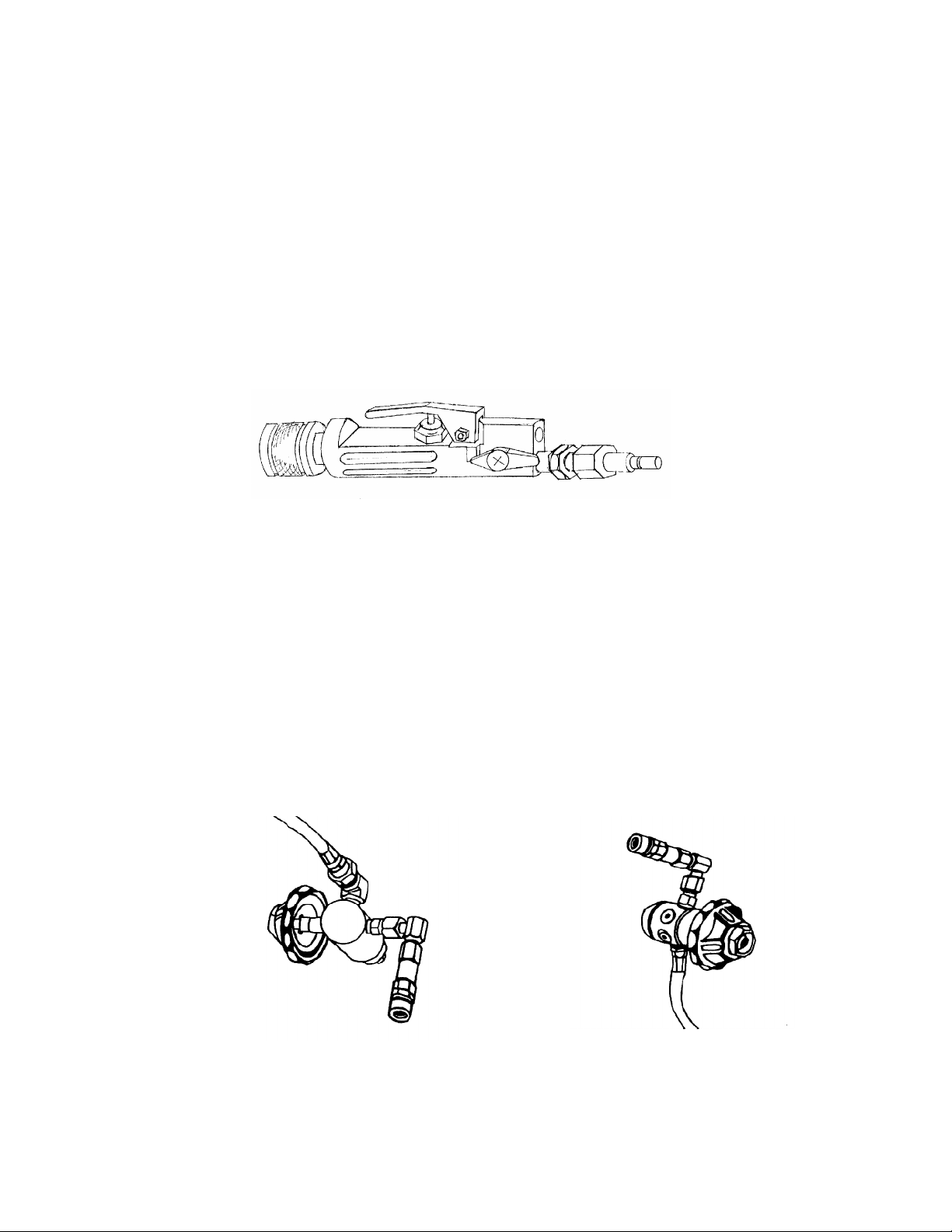
e. Always use the Leather Shield to protect yourself from sparks and splatter.
f. Always remove all personal metal items (i.e., rings, watches, etc.) when working with the torch as
they can trap sparks and slag causing a severe burn and damage to the item.
g. Always keep your head away from the fume plume.
h. Always use adequate ventilation and exhaust at the arc point to keep fumes and gases from your
breathing zone as well as the general area. Special breathing apparatus must be used when
welding or cutting galvanized, cadmium plated (or other heavy metal plated), or painted parts to
avoid inhalation of toxic fumes and gases.
i. Always keep the ignited tip of the cutting rod away from the oxygen cylinder, battery, and oxygen
hoses.
j. Always use extreme caution when operating the torch in windy or other adverse conditions.
k. Never allow falling sparks or molten metal to contact any part of the torch kit. Damage may result
which could render the equipment unsafe to operate.
l. Always use caution when cutting overhead to avoid falling sparks, molten material, and falling
objects.
WARNING

m. Always keep oil and grease away from the torch, oxygen cylinders, valves, regulators, hoses, and
fittings. Never use compressed air, oil, solvents, or other material to clean any part of the oxygen
system. Oxygen reacts explosively when mixed with oil or grease.
n. Never clean any internal part of the oxygen system. Never use compressed air, oil, solvents, or any
other material to clean the oxygen system. The oxygen system could become contaminated and
cause internal burning in the torch or hose. All service on oxygen delivery parts must be performed
by a qualified and knowledgeable technician.
o. Never use a high pressure gas cylinder that does not comply with current inspection and testing
requirements. Always ensure the cylinder is marked with a sticker showing a valid inspection
certification.
p. Never drop a high pressure gas cylinder. Never leave a high pressure gas cylinder in direct sunlight
for prolonged periods. Never expose a high pressure gas cylinder to fire or extreme heat. High
pressure gas cylinders can be dangerous. Use with caution.
q. Always ensure the correct over pressure safety relief device is installed in the high pressure
cylinder valve. Never use a safety relief device whose burst pressure is higher than that
recommended by the cylinder manufacturer.
r. Never leave the torch unattended while the oxygen cylinder valve is open and/or there is pressure
in the hose.
s. Always use a 12-volt DC ignition system. Never use this equipment in conjunction with a welding
machine or with any power source other than a 12-VDC. Although a 12-volt power source is
desirable, a 24-VDC ignition system may also be used.
t. Never touch live electrical parts. Always wear welder's gloves when inserting or removing the rod
into/from the torch and/or extender. Never let the rod touch any unprotected part of the body.
u. Always know the composition of the target material.
v. Always know what is behind the target material.
w. Always ensure that all parts of the torch system are in good working order prior to use to avoid
potential malfunction.
See: American National Standard Z49.1-88 Safety in Welding and Cutting published by the American
Welding Society, 550 N.W. LeJeune Road; Miami, FL 33126.
OSHA Safety and Health Standards 29 CFR 1910 available from the U.S. Department of Labor;
Washington, D.C. 20210.

CHAPTER 1- GENERAL INFORMATION AND SAFETY PRECAUTIONS (cont.)
Section II. EQUIPMENT DESCRIPTION
1-5. PC/TAC TACTICAL CUTTING TORCH SYSTEM. A combination of light weight and
great cutting capability make this back-packed torch system ideal for confined space and remote operations.
Hand-tight fittings and quick connects facilitate assembly and disassembly without the use of tools.
Everything required for field deployment or stationary cutting training is included.
a. Torch Assembly. The torch assembly consists of several parts. The torch body is a combination of
handle, oxygen plug valve, and rod holder. The oxygen control lever allows the operator to throttle
the oxygen flow through the cutting rod. It also includes quick connect fittings, a collet, a collet
washer, and a collet nut. The integral plug valve allows the oxygen cylinder to be opened without
the oxygen flow entering the torch handle and facilitates the use of the RapidFire cutting rod
igniters. The torch comes with one 1/4” and one 3/8” collet.
b. Cutting Rod. The kit is designed to use either 1/4” or 3/8” cutting rods. (3/16” and 1/2” diameter
cutting rods are also available from Broco but are not appropriate for this kit.) Standard rod length
is 18 inches. The 3/8” rod is also available in a 36” length.
c. Leather Shield. The flexible Leather Shield acts as a hand guard and a splatter shield. It attaches
to the torch directly behind the collet nut and is a six inch by six inch square.
d. Oxygen Supply System. The Oxygen (02) Supply System consists of the following component
parts:
1) Oxygen Regulator. There are two versions of regulator sold with the PC/TAC . Both have a
hand-tighten cylinder connection (CGA 540) and a quick connect coupler outlet fitting. The first
version, an industrial, pre-set regulator is for most applications. The second, based on a
modified SCUBA first stage, will maintain output pressure when submerged in water. Cylinder
volume constraints limit the practical working depth to 60 feet. Both versions of regulator are
factory set to provide for a working pressure of 60 to 65 pounds per square inch (psi), which is
the optimum for breaching operations.
INDUSTRIAL REGULATOR SUBMERSIBLE REGULATOR

2) Pressure Gauge. This submersible high pressure gauge is connected to the regulator by an
18 inch length of high pressure hose. It measures the pressure of the compressed oxygen in
the cylinder from zero to 5000 psi and is designed for use with oxygen only.
PC/TAC-G PRESSURE GAUGE
Never use a standard SCUBA pressure gauge as they contain oil.
Do not use compressed air to test the pressure gauge, hose or any other component of the oxygen
supply system as oil contamination may result.
3) Oxygen Hose. The PC/TAC contains a five foot hose and ten foot hose. Both are fitted with
brass quick-connect ends. The five foot hose enables the operator to freely use the torch
system in the backpack configuration. The additional hose may be combined if the system is to
be used from a stationary oxygen source at a distance from the operator.
4) Oxygen Cylinder. The hoop wrapped composite oxygen cylinder is a seamless aluminum
compressed gas cylinder with a 45 cubic foot (cu ft) capacity at 2200 psi. The aluminum shell
is wrapped in a fiber-glass laminate. The cylinder is manufactured in compliance with U.S.
Department of Transportation (DOT) specifications. It has a standard oxygen valve (CGA 540)
for ease of filling and attachment to a regulator.
OXYGEN HOSES, 5' LONG & 10' LONG OXYGEN CYLINDER
WARNING

e. Battery Ignition Components. The battery ignition components are used to ignite the cutting rod
by means of an electric arc.
1) Lightweight Battery. The Lightweight Battery (PC/BISLW) contains a rechargeable 12-volt,
sealed, lead acid (gel-type) battery. The battery provides DC power (through AWG #6 welding
cables) to both the torch and the striker plate assembly. A dead short spark is all that is
necessary for igniting the cutting rod.
PC/BISLW LIGHTWEIGHT BATTERY
2) Striker Plate Assembly. The Striker Plate Assembly, shown with leather sheath, consists of a
replaceable insulated copper grounding plate with battery cable. The 15’ long cable is fitted
with a set of electrical quick-connects allowing it to be shortened to 5’ long for use in a back-
packed mode.
3) Torch Power Cable. The Torch Power cable has electrical quick-connects fitted at both ends
for attachment to the torch assembly and the lightweight battery. The 15’ long cable is fitted
with a set of electrical quick-connects allowing it to be shortened to 5’ long for use in a back-
packed mode.
TORCH POWER CABLE STRIKER PLATE AND
LEATHER STRIKER HOLDER
f. Harness Assembly. The back harness assembly is a high strength, lightweight plastic (SCUBA-
type) frame with padded adjustable shoulder straps. Shoulder straps and chest strap have quick
release buckles. The frame also has nylon cylinder retaining straps. It allows the oxygen cylinder to
be carried in an up-right position on the operator's back.

g. Extender. The extender included in the PC/TAC extends the reach of the rod 14 inches and is
used to enable the operator to employ the torch in otherwise inaccessible places and or make best
use of available cover. A 36” long extender is available from Broco as an optional accessory.
h. Quiver. The quiver is a nylon pouch designed to hold the cutting rods. It is adjustable to
accommodate either 18 inch or 36 inch rods. It has two Velcro fastened belt loops to adjust carrying
height.
i. Safety Equipment. The safety equipment included with each kit consists of welder's gloves and
two pairs of safety glasses with number 5 lenses.
WELDER'S GLOVES & SAFETY GLASSES PC/LWB LIGHTWEIGHT BACKPACK
Never operate this equipment without proper face and eye protection. Always use a number 5 or 6
shade filter lens.
h. Component Case. A plastic Pelicancase, foam lined with internal nylon straps to secure the
hardware and absorb shock. There is a manual pressure relief valve on the front under the handle.
Available Separately:
i. Rod Igniter. The RapidFirecutting rod ignition cartridges are an alternative means of lighting the
torch, eliminating the weight and bulk of the battery, striker plate and related cables.
PC/RFC CUTTING ROD
IGNITION CARTRIDGE
WARNING

1-6. PC/MINI-TAC COMPACT CUTTING TORCH SYSTEM. The smallest exothermic
torch system is well suited to limited cutting operations where portability, speed and cutting capability are
paramount. The PC/MINI-TAC can be used in either a handheld configuration or belt mounted in a traditional
exothermic torch configuration. Hand-tight fittings and quick-connects facilitate assembly and disassembly
without the use of tools.
a. Torch Assembly. The torch assembly consists of several parts. The torch body is a combination of
handle and rod holder. The reversible oxygen control lever (retained by a quick release pin) allows
the operator to throttle the oxygen flow through the cutting rod. A quick-connect fitting at the back of
the torch body is for rapid attachment to either the oxygen regulator or the auxiliary hose assembly.
The torch also includes a collet, a collet washer, and a collet nut. The torch comes with one 1/4”,
one 3/16” and one 3/8” collet.
PC/MT-T1A MINI-TAC TORCH ASSEMBLY
WITH REVERSIBLE LEVER
b. Cutting Rod. The kit is designed to use either 3/16”, 1/4” or 3/8” cutting rods. (1/2” diameter
cutting rods are also available from Broco but are not appropriate for this kit.) Standard rod length
is 18 inches. The 3/8” rod is also available in a 36” length.
c. Oxygen Supply System. The Oxygen (02) Supply System consists of the following component
parts:
1) Oxygen Regulator. The PC/MINI-TAC has a piston type oxygen regulator. It has a hand-
tighten cylinder connection (CGA 540) and a quick-connect coupler outlet fitting. Output
pressure is preset to accommodate 1/4” and 3/16” cutting rods. A heavier spring (included)
must be installed for use with the 3/8” cutting rods. A 3,000 psi pressure gauge is included.
Do not use compressed air to test the pressure gauge, hose or any other component of the oxygen
supply system as oil contamination may result.
2) Oxygen Hose. The PC/MINI-TAC contains a four foot hose fitted with brass quick-connect
ends. A plug valve is installed on the end of the hose assembly that connects to the torch.
3) Oxygen Cylinders. Two fully wrapped composite oxygen cylinders are included with the
PC/MINI-TAC. Each is a seamless aluminum compressed gas cylinder with 15 cubic foot (cu
ft) capacity at 3000 psi. The aluminum shell is wrapped in a fiber-glass laminate. Each cylinder
is manufactured in compliance with U.S. Department of Transportation (DOT) specifications.
WARNING

They have a standard oxygen valve (CGA 540) for ease of filling and attachment to a regulator.
MINI-TAC REGULATOR, HOSE AND CYLINDER
d. Battery Ignition Components. The battery ignition components are used to ignite the cutting rod
by means of an electric arc.
1) Lightweight Battery. The Lightweight Battery (PC/BISLW) contains a rechargeable 12-volt,
sealed, lead acid (gel-type) battery. The battery provides DC power (through AWG #6 welding
cables) to the dual pole striker plate assembly. A dead short spark is all that is necessary for
igniting the cutting rod.
2) Dual Pole Striker Plate Assembly. The Dual Pole Striker Plate Assembly consists of a
handle, two copper grounding plates (poles) and battery cables with electrical quick-connects.
The striker plate functions by the grounding of a cutting rod tip between the two poles, creating
a preheat spark, igniting the cutting rod.
PC/BISLW LIGHTWEIGHT BATTERY PC/SPD-5 DUAL POLE STRIKER PLATE
e. Leather Shield. The flexible Leather Shield acts as a hand guard and a splatter shield. It attaches
to the torch directly behind the collet nut and is a six inch by six inch square.

f. Fanny Pack. The Fanny Pack is a nylon pouch designed to hold an oxygen cylinder with regulator
attached, packet of cutting rods (18” long), torch and hose. Mounting straps and Alice Clips allow
the fanny pack to be carried horizontally or vertically, attached to belt, tactical vest, or load bearing
harness.
g. Safety Equipment. The safety equipment included with each kit consists of welder's gloves, and
one pair of safety glasses with number 5 lenses.
WELDER'S GLOVES & TINTED SAFETY GLASSES
Never operate this equipment without proper face and eye protection. Always use a number 5 or 6
shade filter lens.
h. Component Case. A plastic Pelicancase, foam lined to secure the hardware and absorb shock.
There is a manual pressure relief valve on the front under the handle.
Available Separately:
i. Rod Igniter. The RapidFirecutting rod ignition cartridges are an alternative means of lighting the
torch, eliminating the weight and bulk of the battery, striker plate and related cables.
PC/RFC CUTTING ROD
IGNITION CARTRIDGE
WARNING

CHAPTER 2
PREPARATION
Section I. SETUP PROCEDURES
2-1. PREPARING THE WORK AREA.
Never operate the torch in explosive or flammable environments.
Never cut into unknown material.
Never operate the torch with other personnel or bystanders in front of the torch or in the immediate
work area.
Some plastics, paints, and plated parts give off toxic fumes. Organic materials may be combustible.
Exotic metals may ignite. Glass and thin porcelain may shatter. Rock and minerals may spall.
a. Clear the work area of bystanders/non-essential personnel.
b. Place the oxygen supply and battery in a location away from the immediate work area.
c. Know the composition of the target material. Some metals burn violently. Concrete will spall.
d. Know what is beyond the target material. Never cut near power cables, pipes, or flammable
objects.
e. When the target material is a container or pipe, know the material previously contained therein.
Always thoroughly purge pipelines and containers with an inert gas (such as nitrogen or argon)
prior to cutting.
f. Ensure that falling material (molten metal, sparks, or severed pieces of target material) will not
cause injury to operator or bystanders or cause damage to property.
2-2. PRE-ASSEMBLY INSPECTION.
Never use any equipment which is unsafe or appears to be unsafe. Always replace damaged or worn
components to reduce the risk of injury. Never operate the torch without the flash arrestor and flash
arrestor screen in place.
a. Always inspect the oxygen hose(s), power cables, oxygen quick-connects and electrical
connectors for damage or wear prior to and immediately following each use of the cutting torch.
b. Always inspect the torch assembly, the flash arrestor, and flash arrestor screen for damage or wear
prior to and immediately following each use.
c. Check the battery for leaks. Never use a leaking battery as gases may be toxic and/or combustible.
Seepage may be caustic, harming skin and eyes.
WARNING
WARNING

CHAPTER 2-PREPARATION (cont.)
Section II. PC/TAC ASSEMBLY PROCEDURES
2-3. OXYGEN SYSTEM. (PC/TAC)
To reduce the risk of injury in the event of regulator failure, never stand directly in front of or directly
behind the oxygen regulator while opening the oxygen cylinder valve.
Always keep oil and grease away from the torch, oxygen cylinders, valves, regulators, hoses, and
fittings. Never use compressed air, oil, solvents, or other material to clean any part of the oxygen
system. Oxygen reacts explosively when mixed with oil or grease.
Always make sure the oxygen cylinder is a safe distance from the immediate work area. Never let
sparks or molten material come into contact with the oxygen cylinder.
PC/TAC utilizes a fiber wound composite oxygen cylinder. Never use a cylinder with damaged
windings. Always have a licensed test facility inspect questionable cylinders.
Do not use a torch if there is an oxygen leak.
a. General. The oxygen cylinders included with the Prime-Cut Tactical cutting torch kits are
manufactured in compliance with all applicable US Department of Transportation requirements for
high pressure compressed gas cylinders. The cylinder valve outlet fitting is to the Compressed
Gas Association (CGA) specification 540, the common US industrial oxygen outlet.
High pressure gas cylinders are required to comply with current inspection and testing
requirements. Cylinders must undergo internal visual inspection annually and pass hydrostatic
testing every three years. Always ensure the cylinder to be used is marked with a sticker showing a
valid inspection certification.
b. Export kits. The US standard outlet fitting (CGA 540) is used in many parts of the world. Where it is
not accepted, the British standard for oxygen fittings is usually the local standard (e.g. most of
Asia). Adapters to convert from US to British standard are available from Broco.
1) BR-540 adapter allows the US standard regulators supplied in the tactical torch kits to be used
with British standard oxygen cylinders. This facilitates the use of larger, locally obtained
oxygen cylinders when practicing cutting technique (as opposed to Method Of Entry training).
a) Thread the BR-540 adapter onto the British standard oxygen valve outlet fitting. Tighten
with a wrench.
b) Attach the regulator to the other side of the BR-540 adapter.
2) BR-541 adapter enables the filling of the oxygen cylinders included in the tactical torch kits
by gas suppliers with British standard fill hose end connections. BR-541 adapter can also
be used to fit a British standard oxygen regulator to a US standard oxygen cylinder.
a) Thread the BR-541 onto the US CGA 540 standard oxygen cylinder valve outlet
connection. Tighten with a wrench.
b) Attach the fill hose (or British standard regulator) to the other side of the BR-541 adapter.
3) BR-540 adapter can also be used with a US standard transfill hose assembly to transfer
oxygen between a US standard cylinder and a British standard cylinder.
WARNING

a) Thread the BR-540 onto the British standard oxygen cylinder valve outlet connection.
Tighten with a wrench.
b) Thread one end of the transfill hose assembly onto the other end of the BR-540.
c) Attach the other end of the transfill hose assembly to the US standard oxygen cylinder
valve outlet connection.
d) Follow transfill instructions detailed elsewhere in this manual.
c. Inspect and wipe clean with a clean dry cloth all fittings, hoses, and cables. Ensure there is no
grease, oil, or other contaminant on these items.
d. Ensuring that the oxygen is turned off, place the oxygen cylinder into the back harness assembly:
1) The oxygen cylinder will be in an up-right position.
2) The oxygen outlet shall be positioned toward the user's left shoulder (when wearing the rig).
3) The oxygen cylinder will be located on the back harness assembly so that the cylinder strap is
approximately center on the oxygen cylinder.
4) Tighten the cylinder strap using the tensioner. The cylinder strap must be routed through the
tensioner as shown to remain securely attached to the back harness assembly.
5) Tighten the keeper strap.
ROUTING THE MAIN CYLINDER STRAP

PC/TAC SETUP- OXYGEN SYSTEM
Do not use a wrench to tighten the regulator inlet nipple as damage to the nipple may occur.
e. Connect the oxygen regulator to the oxygen cylinder ensuring that the regulator quick connect
fitting for the oxygen hose is pointed straight down and is parallel to the oxygen cylinder. Note that
the regulator inlet is fitted with a hand-tight nut and Teflon tipped inlet nipple. A complete seal can
be achieved by hand tightening.
f. Attach the pressure gauge hose to the left side shoulder strap of the back harness assembly using
the snap tabs.
g. Connect the five foot oxygen hose to the oxygen regulator by pushing the plug end oxygen quick
connect on the hose into the oxygen quick connect coupler on the regulator. Route the oxygen
hose down along the oxygen cylinder and between the keeper strap and the oxygen cylinder.
h. Attach the torch assembly to the oxygen hose by pushing the plug end oxygen quick connect on
the torch into the oxygen quick connect coupler on the hose. Turn the plug valve to the open
position.
Regulators may fail when pressurized. Never stand directly in front of the regulator while opening
the oxygen cylinder valve. Always stand to the side of a regulator when opening the oxygen cylinder
valve.
Always open the oxygen cylinder valve slowly. Do not allow rapid pressurization of the regulator.
Regulator failure may occur, injuring the operator or bystanders.
i. Standing on the opposite side of the oxygen cylinder from the oxygen regulator, slowly open the
oxygen cylinder valve to start the flow of oxygen. Open the valve all the way, then back off 1/4 of a
turn. Check the pressure gauge on the oxygen regulator to ensure that the oxygen cylinder is full.
j. Check all connections for oxygen leaks by listening for escaping gas. Depress the oxygen control
lever on the torch assembly to verify proper functioning (i.e. not sticking, no obstructions, etc.).
Close the plug valve.
WARNING
CAUTION

2-4. IGNITION SYSTEM. (PC/TAC)
Always use a 12-volt DC ignition system.
Lead-acid batteries generate explosive gases during normal battery operation. Never smoke or allow
spark or flame in the near vicinity of the battery. Always make sure the battery is safely positioned
away from the immediate work area and adequately ventilated. Never let sparks or molten material
come into contact with the battery.
Always wear eye protection and protective clothing. If battery acid makes contact with skin/clothing,
promptly wash with soap and water. If acid makes contact with eyes, flood immediately with running
cold water for at least ten minutes and seek immediate medical attention.
Remove all personal metal items (i.e., rings, watches, etc.) when working with lead-acid batteries as
they can produce a short-circuit current high enough to weld a ring or other like item to metal
causing a severe burn.
Never use the battery while the battery charger is plugged into an AC outlet. Always unplug the
battery charger before attaching the ignition power cables to the battery .
Never let the striker plate accidentally contact the torch, rods, or work area. Electrical shock and
sparks may result.
Do not submerge the battery in water.
The battery can discharge if the striker plate continuously contacts the work area. Exercise caution
to prevent complete discharge of the battery.
The battery should never be left in a total discharged state for an extended period of time. Damage
could be permanent with poor performance as a result. When not in use, recharge at least every
three months.
2-4-1. Lightweight Battery. The Lightweight Battery (PC/BISLW) contains a rechargeable 12-volt,
sealed, lead acid (gel-type) battery. It can be stored in any position. The battery provides DC power
(through AWG #6 welding cables) to the torch and striker plate. A dead short spark is all that is
necessary for igniting the cutting rod.
a. Attach the Lightweight Battery to the Back Harness Assembly waist strap using the metal clips on the
lightweight battery’s nylon cover.
b. Unsnap and lift the front tab of the battery cover, exposing the two electrical quick connect receptacles.
c. Separate the torch power cable into two segments. Connect the 5 foot power cable to the torch by firmly
seating the black plug in the hole in the back of the torch assembly then twisting 1/4 turn to lock in
place.
d. Connect the other end of the 5 foot power cable to the battery. Firmly seat the black plug into the black
receptacle then twist 1/4 turn to lock in place.
e. Separate the striker plate cable into two segments. Connect the striker plate cable to the battery by
firmly seating the red plug into the red receptacle then twisting 1/4 turn to lock it in place.
WARNING
CAUTION

PC/TAC SETUP- IGNITION SYSTEM
There may be times when the backpack need not be used (e.g. training). At these times it may also
be advantageous to use oxygen from a larger cylinder (more cutting duration). In these instances
leave the torch power cable and striker plate cable at 15 feet. Also join the 10 foot long oxygen hose
to the 5 foot hose for a total of 15 feet.
2-4-2. Battery Adapter Clamps. The battery adapter clamps are employed when using any 12-
or 24-volt (DC) power source other than the Lightweight Battery.
PC/BAK BATTERY CLAMPS ADAPT TORCH AND STRIKER
POWER CABLES TO 12 AND 24 VOLT BATTERIES.
NOTE
This manual suits for next models
1
Table of contents