BRODBECK IRONWORKS 2X72 GRINDER User manual

0
2X72 GRINDER ASSEMBLY
INSTRUCTIONS
BRODBECK IRONWORKS LLC
REVISION Q

1
Contents
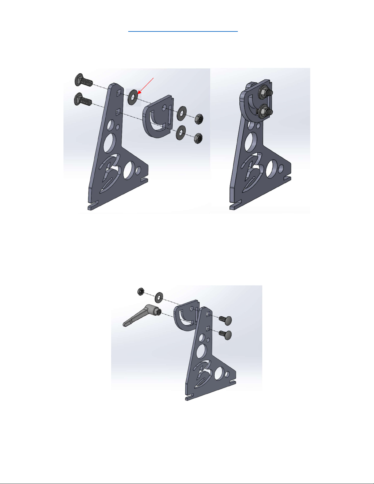
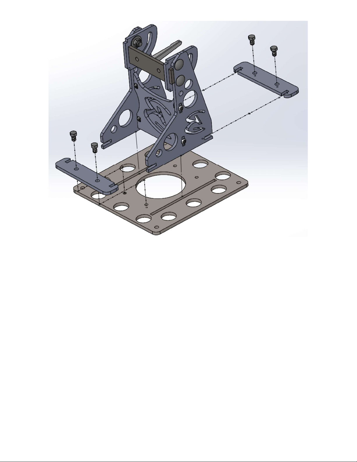
Main Chassis Assembly .............................................................................................................. 2
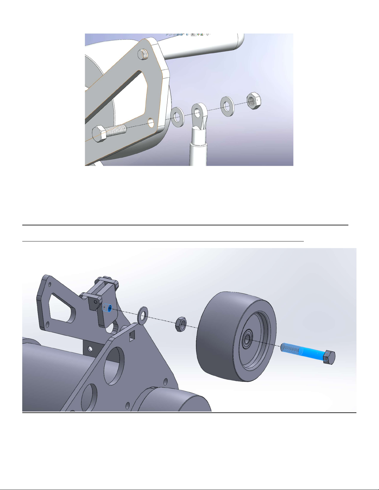
Tracking and Tension Assembly ................................................................................................. 7
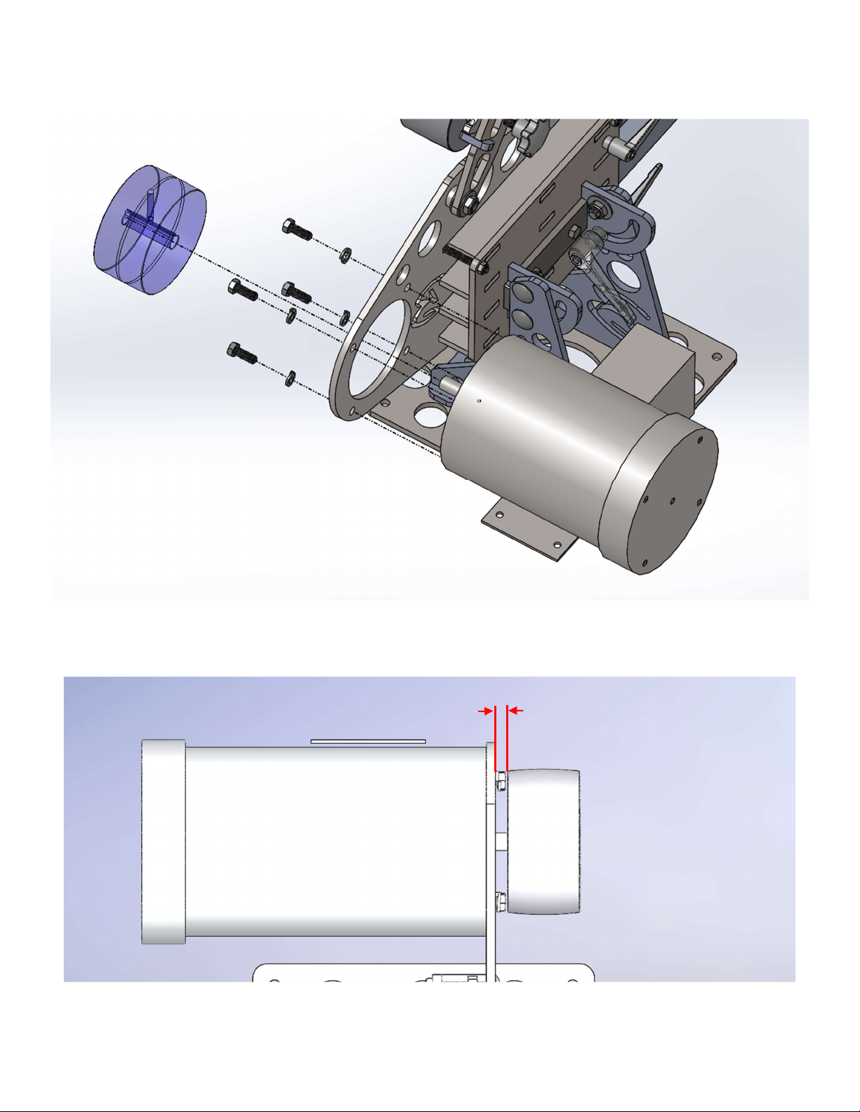
Motor Install .............................................................................................................................. 9
Accessories .............................................................................................................................. 11
Work Rest Assembly ............................................................................................................ 11
Contact Wheel Assembly ..................................................................................................... 12
MAREKO DEEP PLATEN ASSEMBLY ....................................................................................... 13
10” Platen Assembly ............................................................................................................ 15
Small Wheel Attachment Assembly ..................................................................................... 17
Slack Wheel Attachment Assembly ...................................................................................... 18
QUICK CHANGE ATTACHMENT ASSEMBLY ........................................................................... 19
Integral Bolster attachment assembly .................................................................................. 20
Bearing Sets...................................................................................................................... 20
Integral Attachment ......................................................................................................... 21
Wiring Instructions .................................................................................................................. 22
Variable Speed Motor Wiring ............................................................................................... 22
VFD Setup ............................................................................................................................ 24
WARNING:
THE OPERATION OF THIS MACHINE MAY RESULT IN INJURY, DISMEMBERMENT, OR DEATH.
Lockout and secure power source before performing any work on the machine.
Make sure to use adequate personal protection equipment such as eye protection,
respirator, etc. while operating this equipment.
Contact Brodbeck Ironworks LLC for any questions or concerns before operating this
equipment
Ben Secrist 843-457-2755, [email protected]
Vince Molina 301-221-9321, [email protected]

2
Ryan Brodbeck 513-485-8069, [email protected]
Main Chassis Assembly
Place 1 Teflon washer between Hinge Base where the Hinge will rotate (red arrow). Assemble
the first Hinge to the Hinge Base with ½-13 x 1.25” long Carriage bolts, washers, and lock
nuts.
Tighten enough to eliminate any wobble in the hinge. Over-tightening will result in difficulty
transitioning between horizontal and vertical positions.
Place Teflon washer between Hinge Base where the Hinge will rotate. Assemble the second
Hinge to the Hinge Base on the opposite side as the first using ½-13 x 1.25” long Carriage

3
bolts, washers, and lock nut. Use the ½” internal threaded handle on the lower carriage bolt.
This serves as a lock when in the horizontal or vertical position.
Insert the Hinge Lock Plate into the slots in the Hinges. Insert X-Brace into the Hinge Base.
Slide 5/16-18 nylock nuts into the X-Brace. Secure with 5/16-18 x 3/4” long Button Head
Screw by inserting it through the Hinge Base into the nylock nut. Do not completely tighten
the 5/16-18 x 3/4” long Button Head Screw at this time.

4
Interlock the slots in the Base Lock Plates with the slots in the Hinge Base Plates.
Slide the Hinge Bases into slots in the Grinder Base Plate.
Lock in place with two 3/8-16 x 5/8” lg hex head bolts (Apply thread locker to bolts before
installing) per Base Lock Plate.

5
Install the 3/8-16 Threaded Handles into the Hinge-Side Side Plate. Do not tighten down all
the way. Only tighten until the tip of the threads meet the inside face.

6
Lower the Hinge-Side Side Plate onto the Hinges. Make sure the tabs on the Hinges insert into
the slots on the Hinge-Side Side Plate. Use two 3/8-16 x 5/8” lg hex head bolts (Apply thread
locker to bolts before installing).
The 5/16-18 x 3/4” long Button Head Screws in the X-Brace can now be completely tightened.
Install the tabs of (in order from front to back) the Tool Arm Top Plate and Tool Arm Plates
(3), into the slots of the Hinge-Side Side Plate. Place the Belt-Side Side Plate onto the Tool
Arm and Motor Mount Plates.
Insert (4) 5/16-18 X 2-1/2” Carriage Bolts and secure with the 5/16 Nylock Nuts. If you
overtighten the sides plates may bow outward.

7
Tracking and Tension Assembly
Install the Tension Arm using the ½-13 X 1.75” Carriage Bolt, Spacer, Flat Washer(s), and
Nylock Nut. Tighten enough to eliminate side to side wobble. Overtightening can cause
tracking issues. Additional washers are provided to fine tune the tracking.
Install the Gas Spring using 5/16-18 X 1.00” Hex Bolt, a Flat Washer on both sides of each eye,
and Nylock Nut.
Do not overtighten the gas spring bolts. It will bind and cause tracking issues

8
Insert 3/8-16 Threaded Handle into the Tension Arm (apply Loctite).
Install the Tracking Wheel into the Tracking Arm using ½-13 X 3” Hex Bolt, Nylock Nut, and
flat washer.
BE CAREFUL NOT TO OVERTIGHTEN BEARINGS. THE WHEEL SHOULD SPIN FREELY BUT THERE
SHALL NOT BE EXTRA SPACE BETWEEN THE BEARINGS AND NUT OR BOLT HEAD.
Install 3/8-16 Threaded Knob into the Tension Arm. This will be used to adjust tracking in
operation.

9
Motor Install
Install Motor into Belt Side Plate using 3/8-16 x 1 Hex Bolts and Split Lock Washers.
Install Drive wheel and secure with set screw. Align with other wheels to ensure proper
tracking. The drive wheel should be approximately 7/16” off of the side plate
7/16”

10
Notes:
- Make sure all wheel centerlines are aligned with each other to ensure proper tracking.
There may be some variance due to tolerance stack ups.
- To make sure the belt has enough tension, put the belt on all four wheels, pull and hold
down the tension arm all the way, pull the platen arm out until the belt is tight, lock the
platen arm in place, and release the tension arm.
- When adjusting tracking, start off rotating by hand or running the motor at a slow
speed.
- Always adjust the speed on your VFD to 0 when starting after an attachment change
PLACE ALL WARNING LABELS ONTO THE MACHINE IN A VISIBLE
LOCATION.

11
Accessories
Work Rest Assembly
Install Work Rest Spacers and Work Rest Bracket using ½-13 x 2-1/2” Hex Bolts and split lock
washers on the Longest Arm.
Assemble the Large Work Rest & 3/8-16 Threaded Handle with one or two Flat Washers and
slide into slot onto Work Rest Bracket.

12
Contact Wheel Assembly
Place 1 Teflon washer between Arm and Contact Wheel Bracket where the Contact Wheel
Bracket will rotate (red arrow). Install the Contact Wheel Bracket with ½-13 x 2-1/2 Lg
Carriage Bolt, Flat Washers, and Nylock Nuts on the Short Arm.
Insert ½-13 x 2-1/2 Lg Carriage Bolt into the slot and secure with Flat Washers and ½-13”
Internal Thread Adjustable Handle.
Install wheel using ½-13 x 3” Hex Bolt and (2) Nylock Nuts.
BE CAREFUL NOT TO OVERTIGHTEN BEARINGS. THE WHEEL SHOULD SPIN FREELY BUT THERE
SHALL NOT BE EXTRA SPACE BETWEEN THE BEARINGS AND NUT OR BOLT HEAD.

13
MAREKO DEEP PLATEN ASSEMBLY
Place one Teflon washer between Arm and D-Plate where the D-Plate will rotate (red arrow).
Install the Platen D-Plate with ½-13 X 2-1/2 Carriage Bolt, Flat Washer, and Nylock Nut on the
Short Arm.
Insert the ½”-13 X 2-1/2” Carriage Bolt into the slot and secure with ½-13 Internal Threaded
Adjustable Handle.
Install the 2” Idler Wheel into the top (thinner section) of
the Platen D-Plate using ½”-13 X 3” Hex Bolt, Spacer, and
Nylock Nut.
Install the 4” Contact Wheel into the bottom (wider
section) of the Platen D-Plate using ½”-13 X 3” Hex Bolt,
Spacer, and Nylock Nut.
BE CAREFUL NOT TO OVERTIGHTEN BEARINGS. THE WHEEL
SHOULD SPIN FREELY BUT THERE SHALL NOT BE EXTRA
SPACE BETWEEN THE BEARINGS AND NUT OR BOLT HEAD.

14
Install the Platen onto the Platen D-Plate using ¼”-20 Threaded knobs and ¼”-20 X 1”
Carriage Bolts.
Install the Wear Plate to the Flat Platen using short 1/4” Hex Bolts. Align with belt on machine
and tighten in place. Overtightening may strip the threads in the wear plat

15
10” Platen Assembly
Place one Teflon washer between Arm and D-Plate where the D-Plate will rotate (red arrow).
Install the Platen D-Plate with ½-13 X 2-1/2 Carriage Bolt, Flat Washer, and Nylock Nut on the
Short Arm.
Make sure the holes in the D-Plate are on the bottom. (green arrow)
Insert the ½”-13 X 2-1/2” Carriage Bolt into the slot and secure with ½-13 Internal Threaded
Adjustable Handle.
Install the Idler Wheels into the Platen D-Plate using ½”-13 X 3” Hex Bolt, Spacer, and Nylock
Nut.
BE CAREFUL NOT TO OVERTIGHTEN BEARINGS. THE WHEEL SHOULD SPIN FREELY BUT THERE
SHALL NOT BE EXTRA SPACE BETWEEN THE BEARINGS AND NUT OR BOLT HEAD.
Install the Platen onto the Platen D-Plate using ¼”-20 Threaded Handles and ¼”-20 X 1”
Carriage Bolts.

16
Install the Wear Plate to the Flat Platen using short 1/4” Hex Bolts. Align with belt on machine
and tighten in place. Overtightening may strip the threads in the wear plate.

17
Small Wheel Attachment Assembly
Install the Quick Change Offset brackets to the base using ¼” screws.
Install the brace and side plate using the long 5/16” bolts, washers, and nuts. Be sure to install
the fender washers on the front 5/16 bolt to keep wheels from moving side to side. Be sure to
snug and not overtighten these bolts. This can potentially cause tracking issues.
Note: The parts may need a little filing to fit. They are designed to fit tightly.
Install the Idler Wheel into the Small Wheel Bracket using ½-13 X 2-3/4” Hex Bolt, Nylock
Nuts and Flat washers.
BE CAREFUL NOT TO OVERTIGHTEN BEARINGS. THE WHEEL SHOULD SPIN FREELY BUT THERE
SHALL NOT BE EXTRA SPACE BETWEEN THE BEARINGS AND NUT OR BOLT HEAD.

18
Slack Wheel Attachment Assembly
Remove Flat Platen by loosening the ¼-20 Threaded Handles. Slide the Slack Grinding Bracket
onto the ¼-20 x 1” Carriage Bolts and tighten ¼-20 Threaded Handles.
Install the Idler Wheel into the Slack Grinding Bracket using ½-13 X 2-3/4” Hex Bolt, and Nylock
Nuts.
BE CAREFUL NOT TO OVERTIGHTEN BEARINGS. THE WHEEL SHOULD SPIN FREELY BUT THERE
SHALL NOT BE EXTRA SPACE BETWEEN THE BEARINGS AND NUT OR BOLT HEAD.

19
QUICK CHANGE ATTACHMENT ASSEMBLY
Insert ½-13 x 2.5” Carriage Bolts through the base plate into the arm.
Insert ½” Teflon washer between the plate and the arm on the front carriage bolt.
Install the ½-13 lock nut onto the front bolt with a washer.
Install the large black handle with a washer to the back bolt.
Insert the ¼-20 x 1” carriage bolts through the base plate at the desired height.
Install small black handles onto the ¼-20 carriage bolt.
NOTE: If ¼” washers are included, they are from an old revision and are no longer needed on
the current design.
Other manuals for 2X72 GRINDER
1
This manual suits for next models
1
Table of contents
Other BRODBECK IRONWORKS Grinder manuals