Brolight BIM-7001 User manual

OPTICAL POWER METER
光功率计
User Manual

OPTICAL POWER METER
USER MANUAL
Hangzhou Brolight Technology Co., Ltd.
版权所有:杭州博源光电科技有限公司
Ver. 版本:
E
Date 日期:
2018,9,25

Contents
1. Introduction ..............................................................................................................................................................- 2 -
2 Unpacking & checklist..............................................................................................................................................- 3 -
3. Features and Specifications......................................................................................................................................- 4 -
3.1 Features ..........................................................................................................................................................- 4 -
3.2 Specifications .................................................................................................................................................- 4 -
4. Operation guide........................................................................................................................................................- 5 -
4.1 PowerAdapter................................................................................................................................................- 5 -
4.1.1 Power Adapter .............................................................................................................................................- 5 -
4.1.2 Rechargeable battery ...........................................................................................................................- 5 -
4.1.3 Charging ..............................................................................................................................................- 5 -
4.2 Front Panel......................................................................................................................................................- 6 -
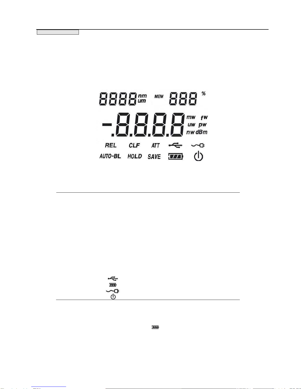
4.2.1 Digital display .....................................................................................................................................- 6 -
4.2.2 Front Panel keys ..................................................................................................................................- 7 -
4.2.3 The default Settings...........................................................................................................................- 10 -
4.2.4 Display mark .....................................................................................................................................- 10 -
4.2.5 Connector description........................................................................................................................- 11 -
5 System operation.....................................................................................................................................................- 12 -
5.1 Connection and Setup...........................................................................................................................- 12 -
5.2 Starting up......................................................................................................................................................- 12 -
5.3 Setting the Wavelength...................................................................................................................................- 12 -
5.4 Setting the Attenuator Mode............................................................................................................................- 13 -
5. 5 Setting the power limit ................................................................................................................................- 13 -
5.6 Measurement ................................................................................................................................................- 13 -
5.6.1Absolute power measurement (mW/dBm)..................................................................................- 13 -
5.6.2 Relative measurment(dB).............................................................................................................- 14 -
5.7 Saving and delete..........................................................................................................................................- 14 -
5.8 Introductions for reseting..............................................................................................................................- 14 -
5.9 Shutdown......................................................................................................................................................- 15 -
6. Maintenance and storage........................................................................................................................................- 16 -

DOCID#: CD-M-BIM-7001D
USER M A N U A L
- 2 -
1. Introduction
This manual suitable to below optical power meter model:
BIM-7001 optical power meter
Thank you for purchasing
hank you for purchasing the high performance optical power meter, featuring a large High-speed
HD display. The range of wavelength and power in the measurement is determined by the
detector.
Default definition
Unless point out specified "Power Meter"
mentioned in this manual refers to the specified model as listed above.
Purpose
The purpose of the manual is to help users to be familiar with and operate the optical power
meter correctly. To obtain full performance from our products, we recommend that you read this
manual carefully.
Chapter 1
1111
T

DOCID#: CD-M-BIM-7001D
USER M A N U A L
- 3 -
2 Unpacking&checklist
Please note the Arrow direction of the box. Always face the Arrow point upwards before o
pening the box.
Please check if there is any missing item according to the checklist.
In case of you find any damage or shortage , Pls contact us immediately.
You have to tell us the model# and SN# (you can find these information on the bottom of
the optical power meter) when you try to get quick service.
Please do not delay the report of damage or shortage. Thus we could be able to find out the
cause of the problems in time.
Chapter 2

DOCID#: CD-M-BIM-7001D
USER M A N U A L
- 4 -
3. FeaturesandSpecifications
3.1 Features
Intelligent background light four liquid crystal display (LCD)
Display in W ,dBm or dB
Auto range,
Auto shutdown
Multiwavelengthsmeasurement
Data stored and read, Out-range alert
PowerManagement Function
Alarm over range
PC software real-time display power value
3.2 Specifications
Chapter 3
Name
BIM-7001
Compatible Detectors
BIM-71 series detertors,BIM-72 series detertors
Spectral Range
0.19um-25um
Power Display Range
1pW-20kW
Displaying Frequency
20 Hz
Internal Date Storage
800 sets
Communication Interface
USB2.0
Display Type
80mm×54mm LCD
Battery Type
Ni-MH rechargeable batteries(3000mAh/pc), optional
Power Adapter
input:100-240VAC output:6VDC,1A
Automatic Shutdown
10 mins
Intelligent Backlight
Support
Weight
0.3Kg
Dimensions
210 mm×120 mm×36 mm
Chapter 3

DOCID#: CD-M-BIM-7001D
USER M A N U A L
- 5 -
4. Operation guide
4.1 PowerAdapter
4.1.1 Power Adapter
In order to make sure this device work well, it is highly recommended that only use the power adapter, which
we shipped together with power meter.
4.1.2 Rechargeable battery
Youcan use two 1.2 V AA N-H rechargeable batteries. To avoid leakage and poor autonomy, onlyuse good
quality batteries in this power meter.
If you have to use non-rechargeable batteries, please use two ordinary 1.5 V batteries. But pls don’t trytouse
the Power Adapter when you use non-rechargeable batteries. Or it will cause explosion and personal injury, and
willhave irreversible damage to instrument,which is not warranty service.
4.1.3 Charging
Thebatteriesneed to be charged if the battery indicator in low level or if it does not power-up when the Power
key is pressed
Connect the power adaptor to the opticalpower meter and the Indicator light will turn red and blink. If the
indicatorlight does not turn red, please check carefully whether the adaptor is well connected with the optical
power meter.Whenthe indicator light turns green, it means the battery is fully charged.
Chapter 4

DOCID#: CD-M-BIM-7001D
USER M A N U A L
- 6 -
4.2 FrontPanel
4.2.1 Digital display
Pic 4-1 shows the layout of the Lcd Screen Display. Form 4-1 is the detail description about these
information.
pic 4-1 Layout of the LCD Screen Display
Information
Description
nm um
Unit of wavelength
MEM
The groups of saved data
%
The measured data as a
percentage of the current range
w mw uw nw fw pw
Unit of absolute power
dBm
It shows whether it is measure
DB or DBM
REL
Relative measurement
AUTO-BL
SmartLight
CLF
Background signal subtraction
(zeroing)
HOLD
Stop Sign
ATT
Attenuator is open
SAVE
Store data
USB
Battery level
Connect the detector
Auto Power -Off
Form 4-1 Display information of BIM-7001
These listed icons you may meet when you use BIM-7001. Each icon represent a real function. After
installing the rechargeable batteries, there will be show on the screen. It shows the battery level
indication.

DOCID#: CD-M-BIM-7001D
USER M A N U A L
- 7 -
4.2.2 Front Panel keys
Figure 4-2 The front panel buttons
1) Power supply
Short press (shorter than 2s. Unless point out specifically, short press means press shorter than 2s) the
power button starting up. Long press (longer than 2s. Unless point out specifically, long press means
(press longer than 2s) shutdown.
2) mw/dBm /MODE
(1)Absolute power measurement
①After starting up, The initial mode is “Absolute power measurement”, you can change the display
unit in mW or dBm by short press this button.
②In Absolute power measurement mode, you can long press this button to enter the Reading
memory data mode. The stored Wavelength is displayed on the upper left corner of the LCD and the
stored power value is displayed in the middle of the LCD. Press button 9 and 10, it display the last or
next data. It will return to Absolute power measurement mode without any operation in 10s.
③In Loading memory data mode, long pressing this button will enter setting lower limits mode. Press
button 9 and 10 to set the lower limits value which displays in the middle of the LCD. When the
measure value lower than it, alarming will occur. It will return to Absolute power measurement mode
without any operation in 10s.
6
5
3
4
1
2
7
9
10
8

DOCID#: CD-M-BIM-7001D
USER M A N U A L
- 8 -
④In setting lower limits mode, long pressing this button will enter setting upper limits mode. Press
button 9and 10 to set the upper limits value which displays in the middle of the LCD. When the
measure value more than it, alarming will occur, It will return to Absolute power measurement mode
without any operation in 10s.
⑤In setting upper limits mode, long pressing this button will enter setting wavelength mode;The
customer can press button 7 and 8 to set the wavelength,and short press button 3 to save the
wavelength.Long pressing button 3 can delete the wavelength. The number of saved wavelengths
will be displayed in the center of the screen. Or without any operation in 10s will enter Absolute
power measurement mode.
⑥In setting wavelength mode, long pressing this button or without any operation in 10s will enter
absolute power measurement mode.
(2)Relative measurement mode
In relative measurement mode, short pressing will be No response. And long press enables you to
switch between relative measurement mode and Reading memory data mode.
3) SAVE/DELETE
(1)In measuring (both Absolute measuring and relative measuring) mode, short pressing will store
the current wavelength and power value into the memorizer. The memorizer can store data up to 800
groups. In setting wavelength mode, short pressing will store the current wavelength .It is invalid to
short press this key in any other mode.
(2)In the measuring (both Absolute measuring and relative measuring)mode, by long Pressing and
holding this button until a "beep" is heard, it can stored the current measurement wavelength, the
upper and lower power limits and attenuator status. Once the measuring mode is stored, the optical
power meter will keep this mode even if you restart it. But if you do not store the measuring mode,
the optical power meter will get back to its factory settings after restarting it.
(3)In Reading memory data mode, long press it will delete the stored information. When the screen
shows “EP”, it means all data has been deleted. In setting wavelength mode, long pressing will delete
the current wavelength. It is invalid to long press this key in any other mode.
(4)In setting wavelength mode, short pressing will store the current wavelength, long pressing will
delete the current wavelength.
4 ) HOLD/ATT
(1)In measuring mode, short pressing will stop refresh, and show the current data. Short pressing
again will restart the data refreshing.

DOCID#: CD-M-BIM-7001D
USER M A N U A L
- 9 -
(2)When using with Attenuator, long pressing this key will show “ATT” on the screen. It means
Attenuator has been opened. When the detector is not connected with the Attenuator, long press will
cause “nA”on the screen, and it means “no Attenuator”.
5) ZERO/REF
(1)In Absolute measuring mode, short press the key will return it to zero, and there will be “CLF”
shown on the screen, and the last measurement is stored as PZ ,and subtracted from all subsequent
measurements P. This causes subsequent measurement calculations shown on the display and
available on the remote interface to use the value ( P− Pz) instead of P. Offset subtraction allows one to
remove the effects of ambient DC signals, by zeroing the display before making a measurement. A
second ZERO key press turns off the ZERO annunciator and stops offset subtraction.
(2)Long press this key, it will enter relative measuring mode after seconds. For details please refer to
section 5.6.2. Long press again this key will exit relative measuring mode.
6) AUTO_BL/AUTO_OFF
(1)Short pressing this key can turn on/of SmartLight. The SmartLight is closed by default. Short press
this key can turn on the SmartLight and it will enter power saving mode without any operation in 30
seconds. Short press again can turn off the SmartLight.
(2)Long press this key can open/close the AUTO POWER OFF function . AUTO POWER OFF function is
closed by default. Short press this key can open AUTO POWER OFF function, and long press again can
close the auto power off function. Under the auto power off function mode, If there is not any
operation in 10mins, the optical power meter will turn off automaticly.
7) Button Down
In measuring mode,Short pressing the key can switch the saved wavelengths. In setting wavelength
mode, short pressing the key can reduce the wavelength, long pressing this key can reduce the
wavelength quickly.
8 ) Button up
In measuring mode,Short pressing the key can switch the saved wavelengths. In setting wavelength
mode, short pressing the key can increase the wavelength,long pressing this key can increase the
wavelength quickly.
9) Button left
In setting up/low limits of the power value mode, short press the key can reduce the power value.
Long pressing it can reduce the power value quickly. In Reading memory data mode, short pressing this
key can read the previous data the memorizer stored.

DOCID#: CD-M-BIM-7001D
USER M A N U A L
- 10 -
10) Button right
(1)In setting up/low limits of the power mode, short press this key can increase the power value,
and long press it can quickly increase the power value. In Reading memory data mode, short press this
key can read the next data that the memorizer has stored. In setting wavelength mode, short press this
key can read the next wavelength that the memorizer has stored.
(2)In measuring mode, long pressing this key (Until a "beep" is heard), that means it enters Factory
data reset node. The wavelength, the up/low limit value are all back to the factory default Settings
4.2.3 The default Settings
The initial settings are as follows, please refer to form 4-2
Function Default
ZERO/REF
ZERO
AUTO_BL
closed
AUTO_OFF
closed
HOLD
closed
ATT
closed
SAVE
closed
DELETE
closed
mw/dBm
W
λ
It is determined by the type
of the detector
MODE
Absolutely measuring mode
MODE(Reading the date
device)
The latest data which was
saved by memorizer
MODE(Power Limit)
It is determined by the type
of the detector
MODE(Power Max)
It is determined by the type
of the detector
Form4-2 BIM-700X Start the default Setting
4.2.4 Display mark
Signs
Instruction
----
It is detecting whether it has
connected the detector
nC
No Connector
nA
The detector without attenuation,
without attenuation is Invalid
EP
No data in memorizer
FULL
The memorizer has been full
OL
Exceed the range.
Erro
Error operating

DOCID#: CD-M-BIM-7001D
USER M A N U A L
- 11 -
Form 4-3 Signals
4.2.5 Connector description
12 3
4
Figure 4-3 Connector
(1) External Power Supply Connector: +6VDC.
(2) DB15: Connector to the detector.
(3) USB: Communication with PC.
(4) Insert the rechargeable battery.

DOCID#: CD-M-BIM-7001D
USER M A N U A L
- 12 -
5 System operation
5.1 Connection and Setup
Connect the detector to the DB15 connector on the flank panel of the optical power meter. The
optional external power supply of the power meter is including rechargeable battery and power
adapter.
Attention: please turn off the power supply when you Connect/Disconnect the detector.
5.2 Starting up
(1)It shows ----after starting up. It will last 1 second and it means the optical power meter is in
self-inspection. When the detector is successfully to connect with the optical power meter, there will
be SN showing on the left of the screen. And then it will enter the measuring mode. If the screen
shows “nC”, that means the detector is fair connection with the optical power meter.
(2)After the optical power meter enter into measurement mode by default, the wavelength will be
shown on the upper left corner. Default wavelength value is determined by the type of detector. For
example, the default wavelength value of Silicon photodetector and Silicon-UV enhanced
photodetector is 650nm, the InGaAs 1350nm and the thermopile 10 um. The middle shows the
measured power value, and the default unit is W; Automatic shutdown and intelligent backlight turn
off by default.
5.3 Setting the Wavelength
For accurate measurement, It is necessary to set the Calibration wavelength to the Incident
wavelength. The Calibration wavelength is indicated in “nm” on the screen. Once starting up, the latest
stored date is used as the Calibration wavelength. (If it is on the first time, the wavelength value is the
default set). If the light source is broadband, use either a value near the center wavelength of the light
or the wavelength with greatest intensity. Pressing the λ▼/λ▲keys will switch the saved
wavelengths .If the customer wants to add a new wavelength,long pressing “Mw/dBm /MODE”key to
enter the setting wavelength model,short pressing λ▼/λ▲to set wavelength and short
pressing”SAVE/DELETE”key to save the wavelength. The number of saved wavelengths will be
displayed in the center of the screen. Long pressing “Mw/dBm /MODE”key again to return the
absolute power measurement mode,and short pressingλ▼/λ▲can switch the saved wavelengths
Chapter 5
Attention
The response of the detector depends on the wavelength of the incident light. Please refer to the manual and
test data to determine suitable wavelength.

DOCID#: CD-M-BIM-7001D
USER M A N U A L
- 13 -
5.4 Setting the Attenuator Mode
If the light intensity more than the detector’s Saturation value, you have to order the attenuator to get
the right data.
In the attenuator mode:
a) ATT signal indication
b) The response of detector - attenuator will be used in the process of verification
Please long press the “ATT” to close the attenuator models when the attenuator is removed.
5. 5 Setting the power limit
If you need to define power measurement range, It can be set to measure the power of the upper and
lower limits. In absolute measurement mode, you can enter setting lower limit mode by long pressing
twice. Long pressing twice again, you can enter setting upper limit mode. Waiting
10seconds or long pressing again, you can enter absolute measurement mode. If the measured
power exceeds the upper and lower limits, it will buzzer. The function is very convenient and effective
to the stability testing of the light source. Without attenuator, the lower power limit is 0.001nW and
upper power limit is 10mW by default. When the attenuator is open(10X、100X or 1000X), the upper
power limit will expand to 10×10mW、10×100mW or 10×1000mW as well.
5.6 Measurement
5.6.1 Absolute power measurement (mW/dBm)
The absolute power measuring has two representation, dBm or W, and short press can change
the measurement units to dBM or W.
dBm reading=10*lg[Net Applied Power/1mW]
Measurment steps:
a)Short press , choose watt or dbm measuring mode, set the wavelength of the light source.
b)Shield the light source which you need to measure
c)Short press and remove the initial background signal. Display should read approximately zero,
but will fluctuate depending upon the variations in the amount of light reaching the detector and the
detector dark current fluctuations.
d) Select the appropriate attenuator according to the photometric intensity, (Suggestion: there is no
need to add the attenuation slices when the light source is lower than 1mw.
e)shine the detector with the signal light source and readout.
Attention
Try to reduce the influence of stray light while measuring. For example, turn off the light in the house
and remove other equipment. Avoid the light focusing on the surface of the detector, or it will damage
the detector. For the saturation and optical damage threshold of the detector, please refer to relative
detector manual.
Attention
Please note that different attenuator will have different light transmission characteristics, the SN of the
attenuator should be matched with the detector while using.

DOCID#: CD-M-BIM-7001D
USER M A N U A L
- 14 -
5.6.2 Relative measurment(dB)
The dB measurement mode displays the absolute value of 10 times the logarithm (base 10) of the
input power, referenced to a power level which is selected by pressing the REF key. The following
equation illustrates this relationship:
dB reading=10*lg[Net Applied Power/Net Referenced Power]
=10*lg{[(P-PZ)]/[(PSTOREF-PZ)]}
P detector input power
PSTOREF Absolute power value of reference light
PZBackground light power value in zero clearing
Measurment steps:
a)Automatically adjust the signal range and choose the wavelength
b)Shield the light source which you need to measure
c)Short press and Remove the initial background signal. The data should be close to zero. But in
fact the data will be fluctuated because of the flux and the dark current of the detector.
d)Let the reference light shine in the detector .
e)Long press REF until the screen shows REL, keep down the reference signal power value PSTOREF
and enter the relative measuring mode.
f)Use the light which need to be measured shining in the detector.
g)Read out.
5.7 Saving and delete
You can long pressing “save” to store the wavelength, the upper and low limite of the power value and
the status of the attenuator. The last stored measurement condition still can be used after restarting.
There is no need for you to resetting. When you long press the “save”, the new data would be stored,
and it will replace the last stored data. If you do not store the measurment data, it will keep the
factory settings mode after restarting. Long pressing (until a “beep” is heard) can delete all stored
data and go back to the factory settings mode.
5.8 Introductions for reseting
When replacing the different types of detector, if the header fails to identify, you can long press the
button (until a “beep”is heard) to restore the factory settings.
Attention
The reference light source and the light source which you want to measure should measure in the same
condition. The background PZshould try to be consistent, to make sure the reference power and the
measured power bigger than PZ, otherwise the dB measurement is no practical meaning, and an Erro
message is indicated on the screen.

DOCID#: CD-M-BIM-7001D
USER M A N U A L
- 15 -
5.9 Shutdown
Long pressing the , when the auto- shutdown function is open, if there is not any operation in
10mins, it will Auto Power -Off . After startup, press the Power Button last more than 1 second again,
the power meter will be shutdown.
Attention
Please read the manual and know well about the specification of the detector, the wavelength and the
power value of the light source before testing. If they are more than detector responsivity and damage
threshold, please choose the right attenuator and do not focus the light source directly on the detector. If
there is something wrong with the power supply system, the host display may be abnormal, please shut
down as soon as possible.And do not start up before the power supply system works well.

DOCID#: CD-M-BIM-7001D
USER M A N U A L
- 16 -
6. Maintenance and storage
In order to ensure the equipment performance and life span, Please use it in temperature 15℃
‐30℃and relative humidity 5%‐85% RH.
Plug adapter connector carefully to avoid scratches port.
Remove the rechargeable battery if you will not use it for a long time.
Pls do not try to use the Power Adapter when you use non-rechargeable batteries, Or it will cause
explosion.
Chapter 6
Table of contents
Other Brolight Measuring Instrument manuals