4.2.
DIFFERENTIAL
AMPLIFIER AND
POWER
AMPLIFIER
The
differential
amplifier
is
of
the constant-current source
type,
which
provides high common mode rejection. On one
input
is
applied the signal
from
the
input
section,
while
the
other
receives feedback
from
the power
section.
The main power
amplifier
components are
two
pairs
of
complementary
transistors (MJE
2955
and MJE 3055)
working
in
class
AB. The standing
current
is
small, ensuring very
low
cross-over
distortion.
The power
transistors
are
placed on a heat sink situated at the back
of
the instrument
(see
Fig.2.2).
Care
should
be
taken
to
allow air circulation around the sink.
A
fifth
transistor
is
placed on
the
sink
for
stabilizing purpose. When
temperature
rises,
this
transistor
will
limit
the standing current in the power
transistors which otherwise
would
increase
too
much. On the sink
is
also
placed a
thermistor
used
to
trigger
the
gating
circuit
(see
section 4.4).
At
low
frequencies, temperature on the sink and in the transistors
will
follow
the current variations, possibly introducing distortion.
Two
transistors
are
provided
to
compensate
for
this effect. The
output
of
the
2706
is
directly
coupled in order
to
avoid the need
for
a
bulky
transformer.
The gain
of
the power amplifier together
with
the
differential
amplifier
is
20 dB, giving
an
overall voltage gain
of
40 dB.
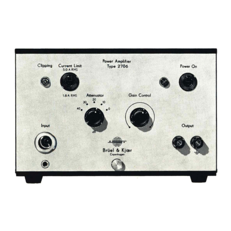
4.3. CURRENT LIMITERS AND CLIPPING DETECTOR
The current
limiting
circuitry
will
limit
the
output
current
to
the selected
value
of
either 1.8 A RMS
or
5.0 A RMS. Current
limiting
is
indicated
by
the CLIPPING lamp. The clipping detector
is
triggered
by
excessive
instantaneous voltage across either
of
the DC biased diodes connected
to
each
branch
of
the differential amplifier. The amber CLIPPING lamp
will
then
be
lit.
The
amplifier
will
continue
to
operate,
but
the
input
signal must
be
reduced
or
further
attenuated
to
resume operation
with
a good
waveform,
as
clipped stgnals introduce considerable distortion.
4.4. TEMPERATURE PROTECTION
Abnormal
load conditions, high ambient temperatures
or
short-circuited
output
could
result in
output
transistor temperatures in
excess
of
design
limits and subsequent transistor failure.
To
prevent
such
damage,
an
NTC
thermistor
is
placed on the heat sink together
with
the power transitors.
Its
9