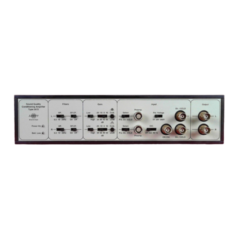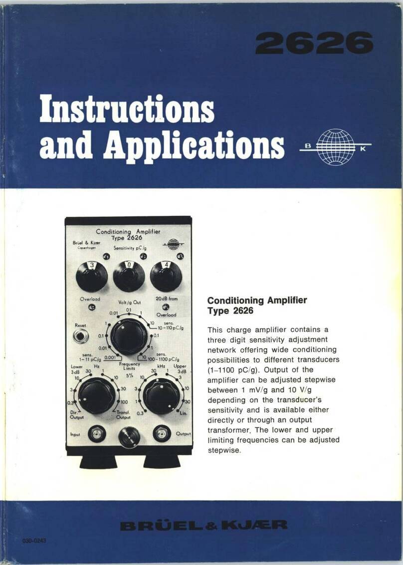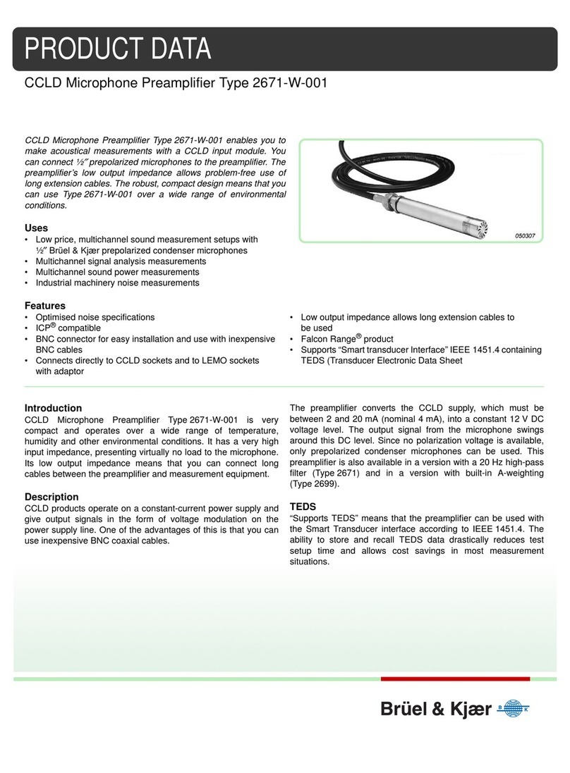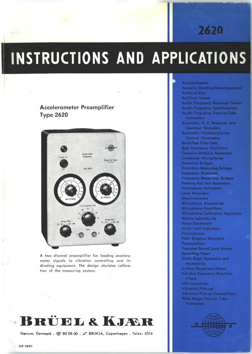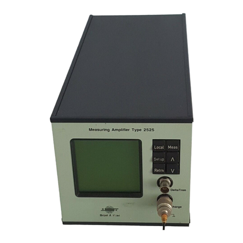
The NEXUS Range of Conditioning Amplifiers
Service Manual Brüel & Kjær
iv
Contents
Optional Filters .......................................................................................................... 26
Inherent Noise* ......................................................................................................... 27
Checking Test Signals ................................................................................................ 27
Overload .................................................................................................................... 29
3.6 Checking DeltaTron Channels ZX 2693 ......................................................................... 31
Checking Calibrated Output..................................................................................... 31
Checking Low-pass Filters* ....................................................................................... 32
Checking High-pass Filters ........................................................................................ 33
Optional Filters .......................................................................................................... 34
Inherent Noise* ......................................................................................................... 35
Checking DeltaTron Supply Current......................................................................... 35
Checking Test Signals ................................................................................................ 36
Overload .................................................................................................................... 36
3.7 Checking Optional Single and Double Integration Filters ZE 0788 ............................. 38
3.8 Checking Optional A-, B-, C- and D-Weighting Filters ZE 0794 ................................... 39
4. Theory of Operation..................................................................................................... 41
4.1 Introduction.................................................................................................................... 42
4.2 Functional Description ................................................................................................... 42
Input Channel Modules............................................................................................. 42
4.3 Block Diagrams............................................................................................................... 42
5. Electrical Diagrams......................................................................................................... 45
5.1 FRP Policy ........................................................................................................................ 46
6. Mechanical Assembly................................................................................................... 47
6.1 Dismantling the Display Unit ....................................................................................... 48
6.2 Dismantling the Motherboard (ZE 0785) ...................................................................... 49
6.3 Dismantling a Channel................................................................................................... 50
6.4 Dismantling the Main Processor Board......................................................................... 51
6.5 Dismantling the Rear Circuit Board (ZE 0786)............................................................... 51
7. Servicing the NEXUS using ATAC ...................................................................... 53
7.1 Introduction.................................................................................................................... 54
7.2 Main Menu ..................................................................................................................... 54
7.3 Service 269X Menu......................................................................................................... 55
Connecting the NEXUS.............................................................................................. 56
Correction Factors...................................................................................................... 57
Adjust Polarization Voltage...................................................................................... 58
Adjust Frequency Response ...................................................................................... 59
7.4 Set Configuration........................................................................................................... 60
