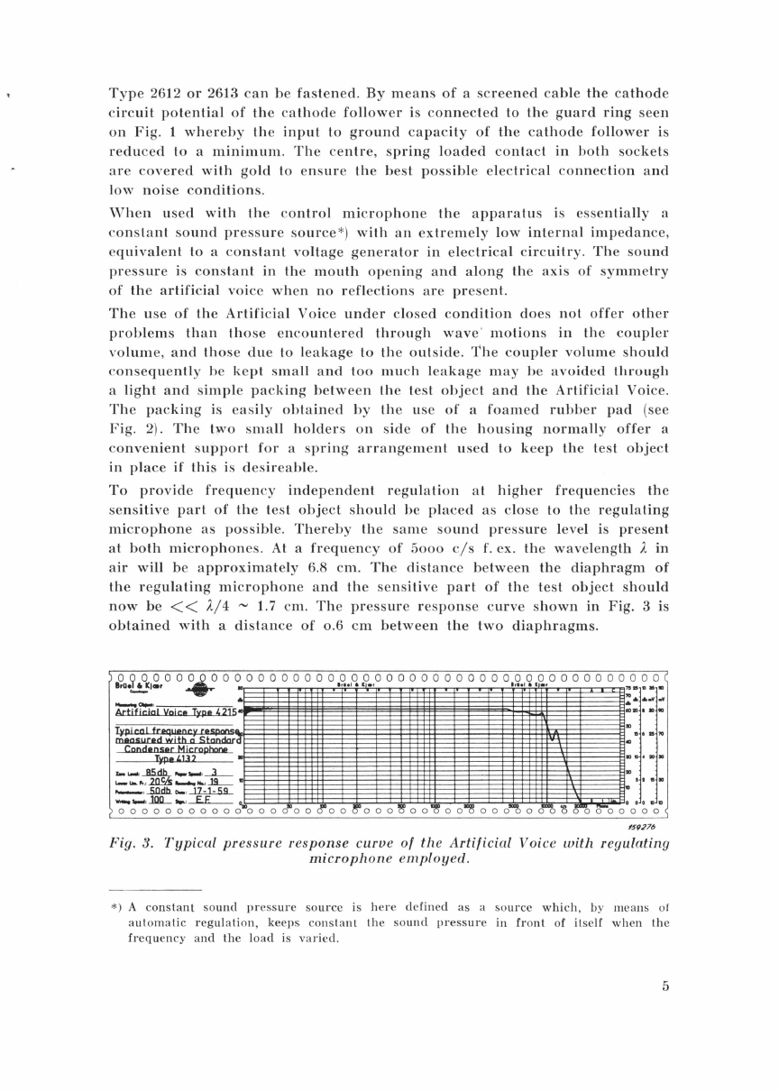
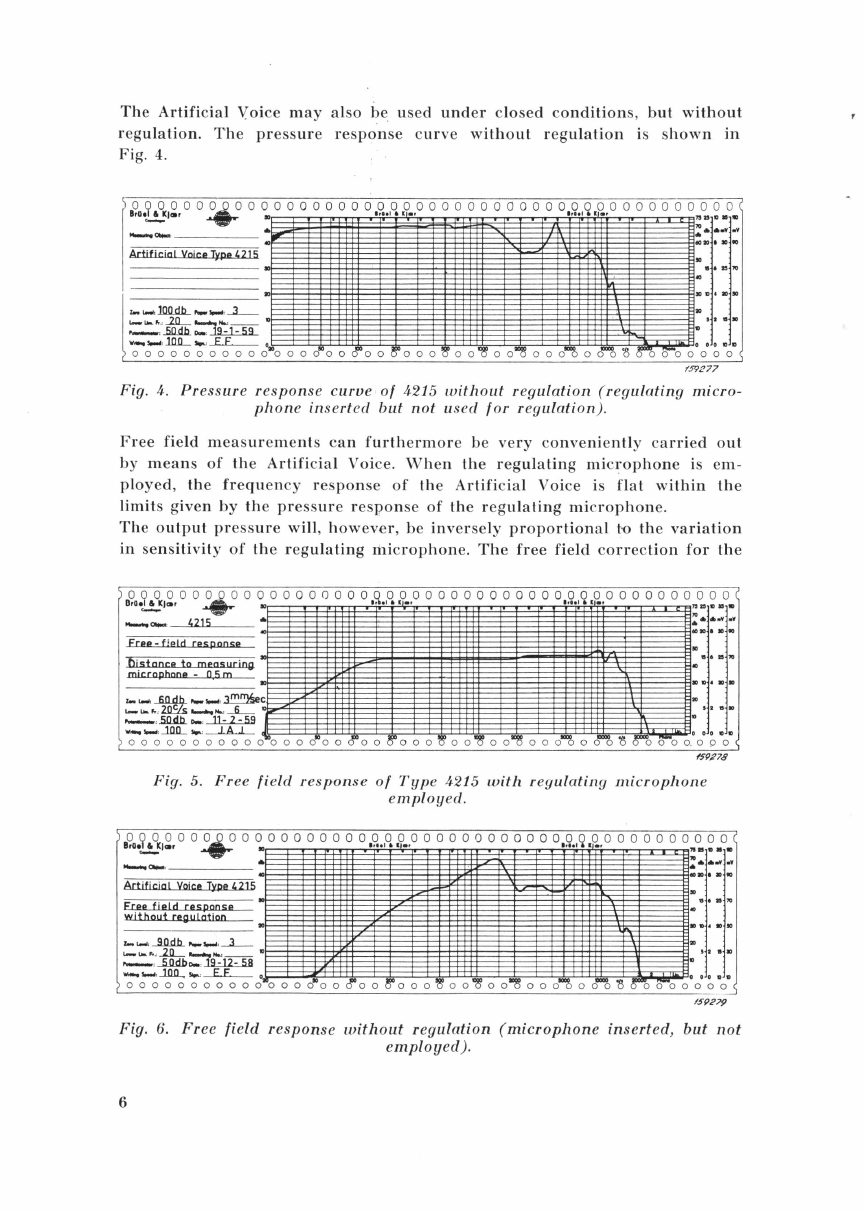
BRUEL & KJAER 4215 User guide

Artificial Voice Type 4215
This
instrument
is
an
acoustically
well-defined
sound
source,
which
may
be
used
for
free-field
measurements
as
wel
l as
for
measurements
under
c
onstant
sound
pressure
conditions.
BHUEL&KJ&R
Nif!rum,
Denmark
•
Phone
80
05 00
Telegrams:
BRUKJA,
Copenhagen
BB
421!5


ARTIFICIAL
VOICE
TYPE
4215.
August
1959

Description
General
Description
Operation
Contents
General
.
.........
..
..
........
.
.........
.
..
.
.....
.
......
...
..
. . .
Recording
th
e
Frequen
cy
Response
of
Mic
rophones
.
..
. .
.. ..
.
...
.
Determin
ati
on
of
Mi
c
rophone
Se
nsitivity
...........
...
.......
..
.
Specification
3
3
4
10
10
11
13
15

Description.
General.
The
Artificial
Voice
Type
4215 is
designed
for
use
in
laboratories
and
pro-
duction
lines
where
a
well
defined
sound
source
is
required,
and
covers
the
frequency
and
pressure
range
that
is
normally
covered
by
the
human
voice.
The
apparatus
is
of
cy
lindrical
shape,
and
it
differs
from
the
artificial
voices
normally
used
for
telefon
measurement
by
its
provision
for
automatic
regulation
of
th
e
sound
level.
It
consists
of
a
small
loudspeaker
mounted
in
a
metal
housing
,
provided
with
a
co
upler
and
with
sockets
for
the
mounting
of
a
regulating
microphon
e
with
Cathode
Follower.
Damping
material
Coupler
\
Gold
covered
contact
Socket
for
regulating
microphone
Guard
ring
Loudspeaker
connect
Gold
covered
contact
l.:j1l~~~-~~f-
Guard ring
contact
for
follower
Fig.
1.
Sectional
view
of
the
Artificial
Voice.
3

Description.
The
sound
producing
element
of
the
Artificial
Voice
is a
small,
dynamic
type
loudspeaker,
the
diameter
of
which
is 90
mm.
It
is
mounted
in
an
aluminum
housing
with
rigid
walls
and
of
cylindrical
shape,
as
shown
in
Fig.
1.
In
front
of
the
loudspeaker
is
placed
a
special
coupler
(mouth
open-
ing)
which
is
made
removeable,
in
order
to
make
it
possible
for
the
user
to
insert
couplers
for
particular
purposes.
The
coupler
is
fastened
by
means
of
a
union
ring,
which
can
also
be
used
lo
fasten
a
lightning
ring,
thus
ensuring
an
airtight
connection
to
the
microphone
under
t
est.
The
special
coupler
supplied
with
the
Artificial
Voice
h
as
an
opening
dia-
meter
of
38
mm.
It
may
be
used
for
measurements
under
constant
sound
pressure
conditions
(provided
th
at
th
e
microphone
can
be
mounted
directly
at
the
opening)
as
well
as
for
free
field
measurements.
Microphone under
test
Regulating
microphone
type
4132
Fig. 2.
Artificial
Voice
with
regulating
microphone
and
test
object
mounted
for
pressure
calibration.
In
the
opening
is
placed
a
socket
for
mounting
of
a
regulating
microphone,
i.e.
the
standard
Condenser
Microphone
Cartridge
Type
4132. As
seen
from
Fig.
2,
lhe
front
of
the
microphone
cartridge
is
exactly
in
level
with
the
opening
of
the
coupler,
whereby
is
obtained
a
sound
pressure
regulation
in
the
very
front
of
the
Artificial
Voice.
By
employing
the
B & K
standard
microphone
the
sound
pressure
can
be
kept
constant
to
within
2
db
in
the
frequency
range
100
cfs
to
7
kc
/s.
The
socket
w'
hich
is
placed
in
th
e
mouth
opening
is
connected
to
another
socket
placed
on
the
side
of
the
housing.
To
thi
s
socket
a
Ca
thod
e
Follower
4

Type
2612
or
2613
can
be
fastened.
By
means
of
a
screened
cable
the
cathode
circuit
potential
of
the
cathode
follower
is
connected
to
the
guard
ring
seen
on
Fig.
1
whereby
the
input
to
ground
capacity
of
the
cathode
follower
is
reduced
to
a
minimum.
The
centre,
spring
loaded
contact
in
both
sockets
are
covered
with
gold
to
ensure
the
best
possible
electrical
connection
and
low
noise
conditions.
When
used
wit.h
the
control
microphone
the
apparatus
is
essentially
a
co
nstant
sound
pressure
source*)
with
an
extremely
low
internal
impedance,
equivalent
to a
constant
voltage
generator
in
electrical
circuitry.
The
sound
pressure
is
constant
in
the
mouth
opening
and
along
the
axis
of
symmetry
of
the
artificial
voice
when
no
reflections
are
present.
The
use
of
the
Artificial
Voice
under
closed
condition
does
not
offer
other
problems
than
those
encountered
through
wave
'
motions
in
the
coupler
volume,
and
those
due
to l
eakage
to
the
outside.
The
coupler
volume
should
consequently
be
kept
small
and
too
much
leakage
may
be
avoided
through
a
light
and
simple
packing
between
the
L
est
object
and
the
Artificial
Voice
.
The
packing
is
easily
obtained
by
the
use
of
a
foamed
ruhber
pad
(see
Fig.
2}
.
The
two
small
holders
on
s
id
e
of
the
housing
normally
offer
a
convenient
support
for
a
spring
arrangement
used
to
keep
the
test
object
in
place
if
this
is
desireable.
To
provide
frequency
independent
regulation
at
higher
frequencies
the
sensitive
part
of
the
test
object
should
be
placed
as
close
to
the
regulating
microphone
as
possible.
Thereby
the
same
sound
pressure
level
is
present
at
both
microphones.
At a
frequency
of
5ooo
c/s
f.
ex.
the
wavelength
2
in
air
will
be
approximately
6.8
em.
The
distance
between
the
diaphragm
of
the
regulating
microphone
and
the
sensi
tive
part
of
the
test
object
should
now
be
<<
2
/4
"'
l.7
em.
The
pressure
response
curve
shown
in
Fig. 3 is
obtained
with
a
distance
of
o.6
em
between
the
two
diaphragms.
a9u.9,
o
~e
1
£,
0
o
~
o o o o o o o o o o,
9.R.O
•.
Oo o o o o o o o o o
o
,g.,
~,q,,o
o o o o o
o
,~~.
o
.,
.........
CIIiil-=
•
=·
.....
Artificial
Vnic• Type 4
215
Condenser
Mjcrophonp
Type
4132
:::~
=~--k=
D
- •
..50dh.
- ·
...l1.:..1.:..5
--;"~~~
·~~
"'
oooo
"'
oo
oo
~
ooo
oo
oo
~o
oo
""o
o"&'8~o
~
oo
0
o
0
~DoD
f!f9276
Fig. 3.
Typical
pressure
response
curve
of
the
Artificial
Voice
with
regulating
microphone
emp
l
oyed.
*)
A
constant
sound
pressure
source
is
here
defined
as
a
source
which
, by
means
of
a
utomatic
regulation,
keeps
constant
th
e
sound
pressure
in
front
of
itself
when
the
frequency
and
the
lo
ad
is
varied.
5

The
Artificial
Voice
may
also
be
used
under
closed
conditions,
but
without
regulation.
The
pressure
response
curve
without
regulation
is
shown
in
Fig.
4.
0~000000000000000000000000000000000000000000000
BrUe~)c.r
......
:
lrt•l
•
I.,
lrhl
•
I.,
::::
:
-"""'
·
..
.........lllO..d.b._,_.,_.,
_J__
"-
IJIL
,
~
__2Q__
......
H..l
--
0
- .
.5ll..d.b.
.....
~
w-
.,_.
,
.1Cll_
.,.
,
___E_E_
o
o o o o o o o o o o o
"'
o o o o
"'
o o
rr'o
o
'tf'
o o o
'8'
o o 'g' o
o
~
o o o
IDOOO
0 0 0
10
D
0 0 0
'8
0 0 0 0 0 0 0 0
Fig. 4.
Pressure
response
curve
of
4215
without
regulation
(regulating
micro-
phone
inserted
but
not
us
ed
for
regulation)
.
Free
field
measurements
can
furthermore
be
very
conveniently
car
ried
out
by
means
of
the
Artificial
Voice.
When
the
regulating
microphone
is
em-
ployed
,
the
frequency
response
of
the
Artificial
Voice is
flat
within
the
limits
given
by
the
pressure
response
of
the
regulating
microphone.
The
output
pressure
will
,
however,
be
inversely
proportional
t'O
the
variation
in
sensitivity
of
the
regulating
microphone.
The
free
field
correction
for
the
0~00000000000000000~000000000000000000000000000
OrUe~)CIIr
......
.:~~~~~t~''l"l'
~~~~·l•
~~~~~~~~~~I•~••~'
'l'i•l•~~~~~:as.,
15
.,
~a.
-
4215
•
::
:::
frep-fip!d
response
bistancp
tp
measuring
mjcrnpbnop
-a5 m
,_
....,,
__60_db_
,_.,_.
,
~c
.._
....
,"~
_
....
,
__6__
0
- •
.5.ll.d.b..
..
.
-..lk..2..::.59
w_._.
,
...l.!l..D_.,.
,..........L..A. o
> o o o o o o o o o o o o o o
c!'
o o
rf'
o o o o o o o
'go
o o
~
o o o-& o oo
'8
JS
-o o o o' o'
~
0o
fSfJR78
Fig.
5.
Free
field
response
of
Type
4215
with
regulating
microphone
employed.
00000000000000000000000000000000000000000000000
llrOe~)CIIr
...
~~~~~~~~
1
":•'1'1'
1
••~~~~~~~~~~
1
'1'"1'
~~~~-~·~~~~~:IS
D • •
....__,a.,-.
.......
Artificial
Voice
Type
4215
Fig.
6.
Free
field
response
without
regulation
(microphone
inserted,
but
not
employed).
6

Ylicrophone
Cartridge
Type
4132
with
pwtection
grid
for
·180°
incidence
is
less
than
1
db
up
to
9
kc
/s,
thus
giving
a
free
field
response
of
the
Artificial
Voice
as
shown
in
Fig.
5. (
Further
information
about
the
free
field
correction
of
the
microphone
is
found
in
the
instruction
manual
Type
4131-32
and
in
the
B. & K.
Technical
Reviews
No. 1
and
2 1959.
In
Fig.
6
the
free
field
response
is
shown
for
the
Artificial
Voice
used
without
regulation.
\Vhen
measuring
c
lose
talking
microphones
such
as
those
used
in
telephone
21U
a.
Fig.
7.
Measuring
arrangements
used
to
obtain
the
curves
shown
in
Fig. 5
and
6
respectively.
7

systems
and
megaphones,
the
distance
between
the
mouth
opening
and
the
microphone
is
so
small
that
interaction
between
the
nearfields
around
the
test
object
and
the
Artificial
Voice
will
influence
the
frequency
response.
The
influence
on
the
sound
pressure
in
the
mouth
opening
caused
by
a
cylindrical
obstacle
with
a
diam
eter
of
40
mm
and
placed
in
a
distance
of
4
em
from
the
opening
does
not
excee
d ± 2
db
at
frequencies
be
low
5ooo
cjs.
(This
counts
with
regulation
as
well
as
without
regulation
).
a9a.W
1
£,
oo
-43
o
o~~o~o~o~o~oio~o~o~,9.~.,0~.~.0.
1
.o~o~o~o~o~o~o~ololololo!,?l
..
,l~!'ol
..
lolol
o
l
o
iolo~o
:0..
~
.o.
--
4115 • •
........
Sound
fje!
d L
em
tOto
• • •
from
mouth
openjng
~S928f
Fig.
8.
Curve
showing
the
influence
of
a 24
mm
microphone
with
flat
front
placed
in
a
distance
of
4
em
from
the
mouth
opening.
C
urve
II
shows
the
frequency
response
as
taken
with
th
e 24
mm
microphone
and
curve
I
shows
the
frequency
response
as
obtained
with
a
microphone
which
has
negligible
effect
on
the
sound
field.
In
Fig.
8 is
shown
the
influence
of
a 24
mm
microphone
with
flat
front
placed
in
a
distance
of
4
em
from
the
mouth
opening.
Fig.
9 s
hows
the
variation
in
fr
e
quen
cy
respon
se
with
di
s
tan
ce
as
m
eas
ured
with
the
above
mentioned
24
mm
mi
c
rophon
e (B. &
K.
Type
4131 ).
The
curve
shown
in
Fig.
10
indicates
the
decrease
in
so
und
pr
ess
ure
level
oooooooooooooooooooooooooooooooooooooooooooc
BrUe~Jatr
....
lrlel
6
ll•r
lr
..
l
a.
ll•r
db
-"'-"'
------.
Frequency
response
120
of
4215
measured
with
4131 -
24mm
em
Condenser
microphone
vmgn"J\
regulation
-----------'
00
_________
90
z..
....,,
__so__
--
·- - -
'-
.....
'"
2..Q__
._
...
,- --
- ._2.5__
"'""~
w;'~
~
';;'~~~o
o o o
"'
o o
~
o
o
'8'
o o o
'8'
o
o
~
o
o
~
o o
o
~
o o
""'&
'8
~
/)""
o c
fS9282
Fig.
9.
The
variation
of
the
frequency
response
with
distance
when
measur
-
ing
the
nearfield
with
the
above
mentioned
24
mm
microphone.
8

-.........
......_
~
........
~
~
"""
~~
~
..............
~~--
...............
.................
..........
2 3 4 6 8
10
20
30
40
60
80
100
200
300
400
600
1000
Distance from mouth opening
in
em
------11~
1~9273
Fig. 10.
The
variation
in
sound
pressure
as a
function
of
distance.
Measured
with
a
microphone
which
has
negligible
effect
on
the
sound
field.
130 db
f;p~%?a3
..
·~v~~r
~'::
=
~.:
-
.,
,..,.5.0J1.b_._l.!l:12:58
at
114
db
"'
·
~---_E.E__
•
.~.
--;;::.
i:">
o o o o o o o
~
o o o o o
'&
o o
"'&
o o
•o
o o
c!"
o o
~o
o
~
o
o o
~
o o
~
o o""" o"'
I:J
··
-o
"''\
o o o
n o o o o o o o o o o o o o o o o o o " o n o o o o o o o o o o o o o o o n
n,o
o o o o o o o o
'1..
•
.!_!!1••+·.
'il
.~
""""-
.....
1
..
--.!tlfi_.
..
..
Third
harman
« •
"'
distortion
gt
114
db
god
gt
at
130
db
f.ll-froQ2Ulici
r
at
114
db
. -
Typical curves
~'::a..~.:
-
..
,..,.5JLd.tL
....
1.9:12:58
""
·
~---.E.E_
0 • '
••
"
p o o o o o o o
~
o o o o o
'&
o o
"'&
o o
""
o o o o o o
8"'
o o
~
o
.:,
o
~
o o
~
o o
"'3"
o
15-
·-o
01
tl
o o o
fSPZU
Fig.
11.
Distortion
generated
in
the
Artificial
Voice
at
sound
pressures
of
1
mbar
and
o.1
mbar.
a)
Fundamental
+
2nd
harmonic
distortion.
b)
Fundamental
+
3rd
harmonic
distortion.
for
increa
s
ing
distance
to
the
mouth
opening.
The
measurement
is
carried
out
at
looo
cjs
and
with
negligible
effect
on
the
sound
field.
Fig.
11
shows
the
distortion
generated
in
the
Artificial
Voice
at
high
sound
pressures
compared
to
the
fundamental
signal.
9

Operation.
General.
As
mentioned
under
"
Description"
the
Artificial
Voice
may
be
used
for
measurements
under
pressure
conditions
as
well
as
for
free
field
measure-
ments.
Typical
applications
for
the
Artificial
Voice
used
under
pressur
e
conditions
are
the
testing
of
microphones
for
oxygen
masks
,
testing
of
silencers,
exhaust
pipes
,
air
inlets
etc.
Applications
for
free
field
measurem
e
nts
are
testing
of
normally
handheld
microphones
and
semiprofessional
microphones
for
tape
recorders,
inter-
communication
sys
t
ems,
public
address
systems,
dictating
machines,
free-
field
labor
atory
t
esting
of
hearing
aids
and
microphones
for
the
100-7ooo
cjs
frequency
range.
The
Artificial
Voice
Type
4215
is
intended
for
use
in
conjunction
with
lhe
Automatic
Frequency
Response
Recorder
Type
3302,
which
consists
of
a
B.F.O
.
Type
1014
and
a
Level
Recorder
Type
2304.
An
arrangement
is
Fig. 12.
Measuring
arrangement
for
recording
the
frequency
response
of
sma
ll
microphones.
10

shown
in
Fig.
11
where
the
Microphone
Amplifier
Type
2604*) is
used
as
a
"Compressor
Amplifier",
which,
when
properly
adjusted,
enables
the
sound
pressure
level
at
the
opening
of
the
Artificial
Voice
to
be
read
off
directly
from
the
indicating
meter.
For
amplification
of
the
test
signal
another
Micro-
phone
Amplifier
Type
2604 is
used,
featuring
the
advantage
of
a
rapid
and
easy
sensitivity
calculation
of
the
microphone
under
test
(see
page
13).
Recording the
Frequency
Response
of
Microphones.
The
measuring
set-up
shown
in
Fig.
12 is
arranged
for
measurements
under
constant
sound
pressure
conditions,
but
may
just
as
well
be
used
for
free
field
measurements.
The
microphone
under
test
can
then
be
mounted
a
short
or
longer
distance
away
from
the
Artificial
Voice,
depending
on
the
applica-
tion.
The
sound
pressure
at
the
diaphragm
of
the
test
object
will
decrease
with
the
distance
according
to
the
curve
shown
in
Fig.
10
and
the
amplification
of
the
amplifiers
must
consequently
be
increased.
The
operation
procedure
given
below
can
be
used
in
both
cases.
Before
the
measurement
is
carried
out,
the
instrument
should
be
adjusted
as
follows:
Type
1014
(The
B.F.O.
of
Type
3302):
Adjust
the
frequency
scale
zero
point
as
described
in
the
instruction
manual
for
Type
1014.
Then
set
the
control
knobs
as
follows:
"Compressor
speed":
"100".
"Output
Voltage":
"0".
"Compressor"
Input
Terminal:
Connected
to
the
output
of
Type
2604 (I).
"Compressor
Voltage":
Approximately
5
on
the
control
knob
marking.
"Load"
Terminals:
Connected
to
the
loudspeaker
terminals
of
Type
4215.
"Impedance"
switch:
6
ohms.
Frequency
Dial:
1ooo
cjs.
The
"Magnetic
Clutch",
"Modulation
Frequency",
"Modulation
Swing"
and
the
"Attenuator"
control
knobs
should
be
set
to
their
"off"
or
"zero"
positions.
The
remaining
control
knobs
should
not
be
touched
after
the
zero
setting
is
carried
out.
Type
2304
(The
Level
Recorder
of
Type
3302):
Insert
the
potentiometer
(50 db)
and
the
recording
paper
QP
3614,
QP
3615
or
QP
3616,
and
set
the
control
knobs
as
follows:
"Lower
Limiting
Frequency":
"20
c/s".
"Potentiometer
db-range":
"50".
"Writing
Speed":
"100
mm/sec".
*)The
Microphone
Amplifiers
Type
2604
may
be
substituted
by
Type
2603
without
any
change
in
the
operation
procedUJ c.
11

"Amplifier":
"On".
"Record/Slider
free":
"Record".
Gear
Box
wheel:
"B".
Input
Potentiometer
Terminal:
Connected
to
the
output
terminal
of
Type
2604
(II).
Zero
Level
Adjustment:
Fully
counterclockwise.
Input
potentiometer
control
knob:
Fully
clockwise
.
Type
2604 (I):
Adjust
the
screw-driver
operated
potentiometer
marked
"
Sensitivity,
Condenser
Microphone"
as
described
in
the
Instruction
Manual
Type
2604
with
respect
to
the
sensitivity
of
the
regulating
microphone.
Then
set
the
control
knobs
as
follows:
"
Input
Switch":
"Condenser
Microphone".
"
Input
Potentiometer
" :
Any
position.
"Co
ndenser
Microphone
"
Input
Terminal:
Connected
to
the
regulating
mi
c
rophone
of
the
Artificial
Voice.
"
Range
Multiplier":
"0
db
(x1)".
"Me
ter
Switch":
"R.M.S.
(Fast)".
"
Power"
Switch:
"On".
"Meter
Range":
"
100
db
(1
V)".
"
Weighting
Network":
"Linear
10-
200ooo
c/s".
Type
2604 (II) :
Adjust
the
sensitivity
of
the
amplifier
as
described
under
"o
peration"
in
the
instruction
manual
for
Type
2604.
Then
set
the
control
knobs
as
follows:
"Input
Switch":
"Direct".
"Input
Potentiometer":
Any
position
.
"Range
Multiplier":
"0
db
(x
1)
".
"Meter
Switch":
"R.M.S.
(Fast)".
"
Power"
Switch:
"On".
"Me
ter
Range
":
"100
db
(1
V)".
"
\Veighting
Network":
"
Linear
".
When
the
instruments
are
adjusted
as
described
above,
the
actual
measure-
ment
can
take
place.
1.
Place
the
microphon
e
to
be
tested
in
front
of
the
acoustical
coupler
of
the
Artificial
Voice.
The
microphone
should
fit
airtight
to
the
coupler,
eve
ntually
mounted
by
means
of
a
pi
ece
of
foam
rubber,
when
pr
ess
ure
conditions
are
desired
.
2.
Connect
the
output
leads
of
the
microphone
under
test
to
the
input
jack
of
the
Microphone
Amplifier
Type
2604
(II).
3.
Turn
the
Output
Voltage
"
knob
of
th
e
B.F.O.
to
maximum.
4.
Rotate
the
"Compressor
Voltage
"
knob
of
Type
1014
until
the
meter
pointer
of
the
Microphone
Amplifier
Type
2604
(I)
deflects
to
the
10
db
mark
on
the
db
scale.
12

A
sound
pressure
level
of
110
db
re
2 X 10⁻⁴
,ubar
is
then
obtained
in
front
of
the
microphone.
(
If
a
sound
pressure
level
of
f.
inst.
90
db
is
required,
the
"Me
ter
Range"
s
witch
of
Type
2604 (I) is
set
to
80
db
SPL.
The
sound
pressure
level
is
then
80
db
+
10
db
(
read
off
from
the
scale)
=
90
db.
When
low
sound
pr
ess
ure
levels
are
desired
,
the
loudspeaker
should
be
co
nnected
to
the
Attenuator
Output
of
th
e
B.F.O.
,
in
order
to
mak
e
th
e
compressor
circuit
work
·
in
th
e
middl
e
of
its
working
range
,
see
also
the
instruction
manual
for
type
1014
}.
Th
e
mov
e
ment
of
th
e
met
er
pointer
of
101-t-
should
preferably
fall
within
-10
db
to +
10
db
on
the
met
er
sca
le
of
th
e o
sc
illator
wh
en
th
e
frequ
e
nc
y
sca
le is
scanned.
5.
Adjust
the
range
switches
on
the
Type
2604 (II)
until
a
suitable
deflec-
tion
of
the
Level
Recorder
stylus
is
obtained
(
f.
ex.
around
40
db
).
6.
Scan
Lhe
frequency
rang
e
of
Type
1014
to
make
sure
that
the
stylus
deflection
of
the
Level
R
eco
rder
is
well
within
the
width
of
the
record-
ing
paper
for
all
frequencies.
Otherwis
e
re-
a
djust
the
amplification
of
Type
2604 (II)
or
adjust
Lh
e "
Input
Potentiometer"
knob
on
the
Level
H.
eco
rder.
7.
Set
lh
e
fr
e
qu
e
ncy
dial
of
th
e
B.F.O.
to 20 c/ s.
8.
Set
the
"Mag
netic C:lutch" to "
On
".
9.
Adjust
th
e
Re
co
rding
Pap
er
until
th
e
writing
arm
indi
ca
t
es
20
cjs,
by
turning
the
finger
wh
eel
placed
to
th
e
right
of
th
e
gear
box.
10.
Pu
sh
Lh
e
gear
lever
mark
ed
3
mm
/sec.
11.
Start
th
e
motor
by
mean
s
of
the
toggl
e
sw
itch
mark
ed
"Mo
lor
".
The
frequency
rang
e is
now
automatically
scanned,
and
the
fr
e
quen
cy
re
spo
n
se
curve
of
th
e
mi
c
rophone
und
er t
es
t is r
eco
rd
ed
on
th
e
fre-
qu
e
ncy
ca
librated
paper.
Determination
of
Microphone
Sensitivity.
Th
e sens
itivit
y
of
th
e
mi
c
rophon
e
und
er l
es
t
can
be
determined
very
con-
veniently
when
the
sound
pressure
lev
el
at
the
opening
of
the
Artifical
Voice
is
adjusted
to
74
db
SPL
which
is e
qual
to
1
,ubar
or
to 134
db
SPL
which
is e
qual
to 1
mbar.
vVith
lh
e
sound
pressure
lev
el
se
t
to
74
db
plu
s
as
many
db
as
th
e
sound
pressure
ha
s de
creased
according
to
Fig.
10,
th
e
range
switches
of
th
e
microphon
e
amplifier
2604 (
II
) is
adjusted
until
a
s
uitabl
e de
flection
is
obtained
on
th
e me
ter
.
Th
e m V r
ea
ding
on
the
mel
er
sca
le
in
conjunction
with
the
"
Meter
Range"
a
nd
"Range
Multiplier"
sw
itch
es
then
directly
indicates
th
e
sensitivity
of
th
e
mi
c
rophon
e
being
t
es
ted
in
m V
per
,ubar.
The
Automatic
Frequency
R
es
pon
::;
e He
co
rd
er
Type
3302
s
hown
in
Fig.
12
can,
if
desired,
be
replac
ed
by
th
e
Audio
Frequency
Response
Tra
ce
r
Typ
e
13

4707,
which
features
a
rapid
visual
check
of
the
microphone
response
curve.
This
might
be
especially
convenient
when
the
measuring
arrangement
is
used
in
production
line
test
systems.
The
operation
procedure
is
similar
to
the
one
described
above,
except
for
the
settings
of
the
Automatic
Frequency
Response
Recorder
Type
3302.
For
the
operation
of
the
A.F.
Response
Tracer
Type
4707,
set
the
control
knobs
as
follows:
14
Adjust
the
frequency
scale
zero
point
as
described
in
the
instruction
manual
Type
4707.
Then
proceed
as
follow
s:
"Co
ndenser
r.p.n1." :
"3",
"6"
or
"12"
r.p
.In.
"Compressor
Speed":
"S
low".
"Co
mpressor
Voltage":
10
on
th
e
control
knob
marking.
"Compressor
Input":
Connected
to
the
output
of
Type
2604
(1).
"A.F.
Output
Voltage":
"
0".
"A.F.
Output"
socket:
Connected
to
the
loudspeaker
terminals
of
Type
4215.
"Attenuator":
"6
ohn1s,
5
volts".
"T
racer
Input"
socket:
Connected
to
the
output
of
Type
2604 (
II
).
"Lower
Limiting
Frequency":
"20
c/s".
"Tracer
Input
Voltage":
Should
be
adjusted
to
give a
suitable
zero
level,
f.
ex.
10
mV.
Turn
the
"AF
Output
Voltage"
knob
fully
clockwise
and
adjust
the
"Co
mpressor
Voltage"
knob
till
a
suitable
output
level
is
obtained.

Specification
Frequency
Response
(with
regulating
microphone):
Linear
to
within
± 2
db
from
100 cj s to
7ooo
cjs
(see
Figs.
3
and
5).
Max.
Sound
Pressure
Level:
115
db
for
free-field
measurements
, 4
em
from
mouth
opening.
Approx.
130
db
for
measurements
under
constant
sound
pressure
conditions.
(
db
re
2 X 10⁻⁴
,ubar).
Obtained
when
connected
to
B.F.O.
Type
1014, 6 Q
output
terminals.
Distortion:
Less
than
1 %
at
looo
cjs
at
sound
pressures
lower
than
115
db
re
o.0002 ,ubar.
Mouth
Opening:
Diameter
of
aperture
is 38
mm
(1.5").
May
be
used
for
1neasurements
under
co
nstant
sound
pressur
e
conditions
as
well
as
for
free
field
measurements
.
Power
handling
capacity:
3
Watt.
Dimensions:
Height
10.5
em
(414
"),
Diameter
10.5
em
(4
1
,4
").
Weight:
2
kg
(4
lbs.
).
15


B K
P
rinted
in
Copenhagen,
Denmark
Au
g
ust
195
9
Table of contents
Other BRUEL & KJAER Laboratory Equipment manuals
Popular Laboratory Equipment manuals by other brands

Biotage
Biotage Turbo Vap II quick start guide

Varian
Varian CP-3800 GC Getting started manual

Fluke
Fluke i40s-PR instruction sheet

Caframo
Caframo Real Torque Digital Stirrers instruction manual

Sartorius Stedim Biotech
Sartorius Stedim Biotech Palletank user manual

Sartorius
Sartorius Vivaspin 500 Instructions for use

IEC
IEC Centra-CL3 Series Operation manual

Insphero
Insphero GravityTRAP product manual

NoiseKen
NoiseKen ESS-2000AX instruction manual

NEW BRUNSWICK SCIENTIFIC
NEW BRUNSWICK SCIENTIFIC MP-1000 Pourmatic Guide to operations

Wasatch Photonics
Wasatch Photonics Cobra OCT Getting started guide

SII
SII Vortex-ME4 user manual