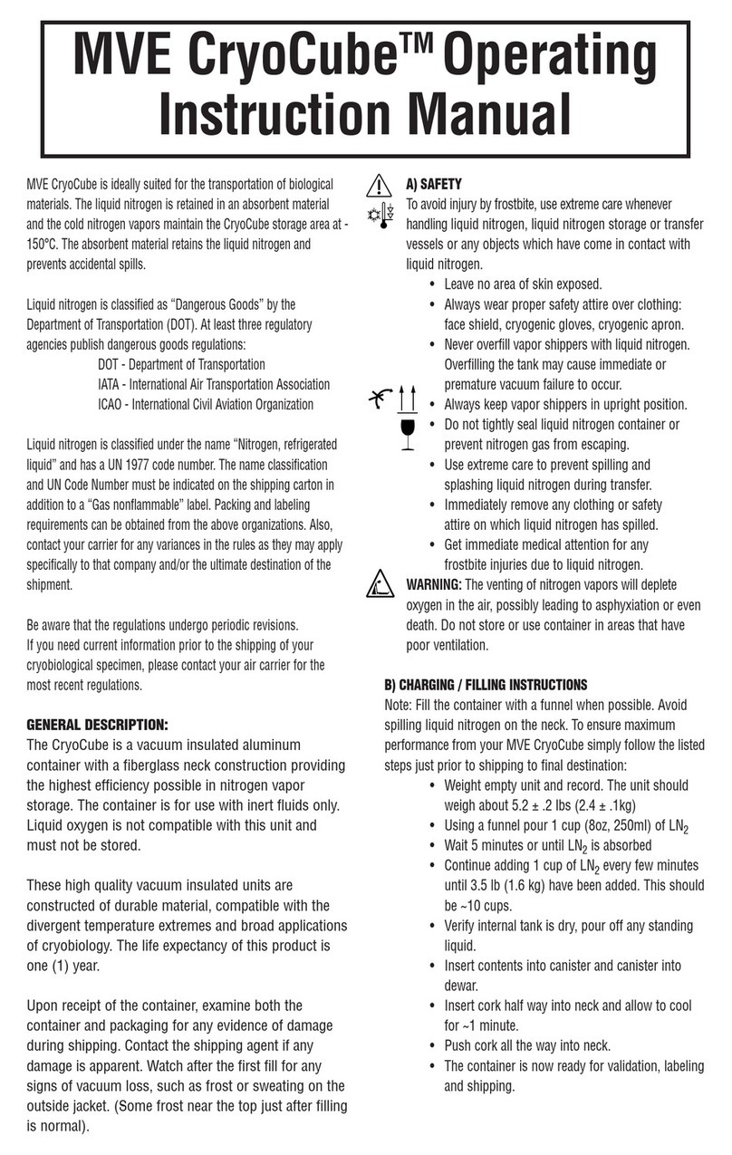
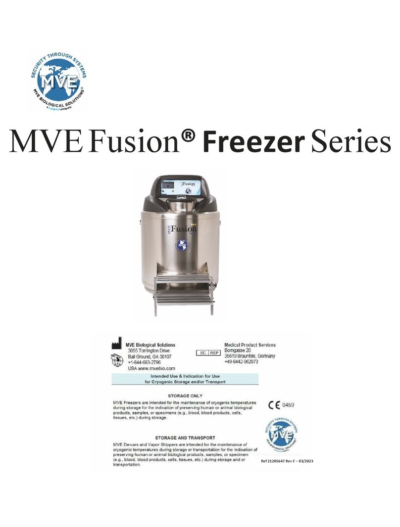
MVE LN2 Tx User manual

PN 15098830 Rev A — 1
MVE LN2 Tx
Liquid Nitrogen Transfer System
OPERATORS MANUAL
BioMedical
Chart, Inc.
BioMedical Group
2200 Airport Industrial Drive Suite#500
Ball Ground, Georgia 30107
is Operators Manual covers use and
maintenance of the MVE LN2 TX. It is
intended for use by experienced personnel
only.

2 — Ln2 Tx Instructions
Chart Inc.
Biomedical Division
2200 Airport Industrial Drive, Suite 500
Ball Ground, GA 30107
Customer/Technical Service Americas:
Toll Free Phone: 1-800-482-2473
Toll Free Fax: 1-888-932-2473 (To place an order)
Fax: 1-770-721-7758
customerser[email protected]
Table of Contents
Contents
Contents...............................................................................................................................................................................2
Table of gures ....................................................................................................................................................................2
General.................................................................................................................................................................................3
System Description.............................................................................................................................................................3
Handling of Liquid Nitrogen ............................................................................................................................................3
Handling Cryogenci Storage Dewars...............................................................................................................................3
Liquid Nitrogen Safety Precautions .................................................................................................................................4
Handling of Liquid Oxygen...............................................................................................................................................5
Warnings..............................................................................................................................................................................5
Setup.....................................................................................................................................................................................6
Warranty ..............................................................................................................................................................................7
Maintenance........................................................................................................................................................................7
Troubleshooting..................................................................................................................................................................7
Technical Assistance...........................................................................................................................................................7
Table of Figures
Figure 1, LN2 TX................................................................................................................................................................3
Figure 2, Typical cryogenic Dewar...................................................................................................................................3
Figure 3, Nitrogen Gas connection ..................................................................................................................................6
Figure 4, Nitrogen Gas supply hose connected to the LN2 TX....................................................................................6
Figure 5, Nitrogen Gas Supply hose connected to Gas Use valve on liquid cylinder................................................6
Figure 6, Suction end of LN2 TX......................................................................................................................................6
Figure 7, Suction end of LN2 TX placed inside supply container................................................................................6
Figure 8, Discharge end of LN2 TX .................................................................................................................................7
Figure 9, Discharge end of LN2 TX placed inside the receiving container ................................................................7
Customer/Technical Service Europe
Phone: +44 (0) 1344 403 100
Fax: +44 (0) 1344 427 224
techservice.euro[email protected]
customerser[email protected]m
Customer/Technical Service Australia/Pac Rim
Phone: +61 297 494333
Fax: +61 297 494666
techservice.a[email protected]
customerser[email protected]m

PN 15098830 Rev A — 3
General
e MVE LN2 TX (Liquid Nitrogen Transfer system) is a system
that allows liquid nitrogen (LN2) to be drawn out of an open
container and transferred to another open container.
It can be employed to remove liquid from a freezer to facilitate
servicing, or to remove excess liquid from a dry shipper aer
charging.
System Description
e MVE LN2 TX uses a high velocity nitrogen gas stream to
create suction (vacuum) at the inlet that draws liquid up into the
transfer device. Once the liquid is drawn into the gas stream, the
liquid is pushed through the transfer tube and hose by the gas
stream.
e high velocity nitrogen gas is discharged through annular
orices around the ID of the suction head that are directed toward
the outlet of the suction head into the transfer tube. e use of
suction from the far end of a hose to draw LN2 from a container
results in the liquid ashing to gas. e liquid may be removed
from a container, but is not conserved. e placement of the
suction head at the inlet end of the system minimizes the low
pressure (vacuum) area in the transfer system, thus minimizing
ash loss. Once the liquid is entrained in the gas stream, it is re-
pressurized to further minimize ash loss.
N2 Gas Connection
LN2 Outlet
Flex Transfer Hose
LN2 Inlet (Vacuum)
Figure 1: LN2 Tx
HANDLING OF LIQUID
NITROGEN
GENERAL
Liquid Nitrogen (LN2) is used in the operation of the MVE LN2
TX. Although not explosive, there are a number of safety consid-
erations to keep in mind in the handling of LN2.
PROPERTIES
Nitrogen is a colorless, odorless, tasteless gas. Gaseous Nitrogen
makes up about 78% of the Earth’s atmosphere. Once collected
and isolated, Nitrogen will liquefy when cooled properly. e
properties of LN2 are as follows:
PROPERTY VALUE
Boiling Point @ 1 ATM, in °C...........................-195.8
ermal Conductivity (Gas), w/m2 °K............0.079
Latent Heat of Vaporization, Btu/Liter ............152.0
Liquid Density, lb/liter @ 1 ATM .....................1.782
Expansion Ratio @ STP .....................................746:1
HANDLING
CRYOGENIC
STORAGE DEWARS
Cryogenic containers (Dewar’s) must be operated in accordance
with the manufacturer’s instructions. Safety instructions will also
be posted on the side of each Dewar. Cryogenic Dewars must be
kept in a well-ventilated place where they are protected from the
weather and away from any sources of heat. A typical cryogenic
Dewar is shown in Figure 2.
Figure 2: Typical Cryogenic Dewar

4 — Ln2 Tx Instructions
LIQUID NITROGEN
SAFETY
PRECAUTIONS
Transferring LN2 and operation of the storage Dewar controls
should be in accordance with the manufacturers/supplier Instruc-
tions. During this transfer, it is important that all safety precau-
tions written on the storage Dewar and recommended by the
manufacturer be followed.
WARNING
• Nitrogenisapotentialasphyxiateandcancauserapidsuo-
cation without warning. Store and use in area with adequate
ventilation. DO NOT vent container in conned spaces.
DO NOT enter conned spaces where gas may be pres-
ent unless area has been well ventilated. If inhaled, remove
to fresh air. If not breathing, give articial respiration. If
breathing is dicult, supplemental Oxygen may be re-
quired. SEEK MEDICAL ATTENTION IMMEDIATELY.
• LiquidNitrogencancauseseverefrostbitetotheeyesor
skin. DO NOT touch frosted pipes or valves. In case of
frostbite, consult a physician at once. If a physician is not
readilyavailable,warmtheaectedareaswithwaterthatis
near body temperature.
• NeverplaceLN2inasealedcontainerwithoutapressure
relief device. e expansion ratio of LN2 to N2 gas is ap-
proximately 1 to 700; i.e. 1 cubic foot of LN2 becomes 700
cubic foot of N2 gas at 0psi when evaporated.
e two most important safety aspects to consider when han-
dling LN2 are adequate ventilation and eye and skin protection.
Although Nitrogen gas is non-toxic, it is dangerous in that the
gas will displace the Oxygen in a normal breathing atmosphere.
Liquid products are of even greater threat since a small amount
of liquid evaporates to create a large amount of gas. erefore, it
is imperative that cryogenic supply and storage Dewars be stored
and operated in open and well-ventilated areas.
PersonstransferringLN2shouldmakeeveryeorttoprotect
the eyes and skin from accidental contact with liquid or cold gas
issuing from the Dewar. Protect the eyes with a full-face shield or
chemical splash goggles. Safety glasses (even with side shields) are
not adequate. Always wear cryogenic gloves or equivalent when
handling anything that is or may have been, in contact with the
liquid, cold gas, cold pipes, or equipment. Long-sleeve shirts and
cu-lesstrousersofsucientlengthtopreventliquidfromenter-
ing the shoes are recommended.
RECOMMENDED FIRST AID
Every site that stores and uses LN2 should have an appropri-
ate Material Safety Data Sheet (MSDS) present. e MSDS may
be obtained from the manufacturer/distributor. e MSDS will
specify the symptoms of overexposure and the rst aid to be used.
A typical summary of these instructions is provided as follows.
• Ifsymptomsofasphyxiasuchasheadache,drowsiness,
dizziness, excitation, excess salivation, vomiting, or uncon-
sciousness are observed, remove to fresh air. If breathing is
dicult, give oxygen. If breathing has stopped, give articial
respiration. CALL A PHYSICIAN IMMEDIATELY.
• Ifexposuretocryogenicliquidsorcoldgasesoccurs,restore
tissue to normal body-temperature (98.6°F) as rapidly as
possible, and then protect the injured tissue from further
damage and infection. Call a physician immediately. Rapid
warmingoftheaectedareasisbestachievedbybathingit
in warm water. e water temperature should not exceed
104°F (40°C). Under no circumstances should the frozen
part be rubbed, either before or aer warming. If the eyes
are involved, ush them thoroughly with warm water for at
least 15 minutes. In case of massive exposure, remove cloth-
ing while showering with warm water. e patient should
not drink alcohol or smoke. Keep warm and rest. CALL A
PHYSICIAN IMMEDIATELY.

PN 15098830 Rev A — 5
HANDLING OF
LIQUID OXYGEN
GENERAL
Liquid Oxygen (O2) is created by liquefaction in the operation of
the MVE LN2 TX. Because the liquid temperature of Nitrogen
is colder than that of Oxygen, Oxygen in the atmosphere will
condense on the exposed cold surfaces of the LN2 TX during a
transfer.
Although not ammable or explosive by itself, it is an oxidizer
that will accelerate combustion of ammable materials and allow
some materials that are not normally ammable to burn.
All of the cold exposure issues discussed above in the section on
handling liquid nitrogen also apply to liquid oxygen. ere are
additional safety considerations to keep in mind in the handling
of O2. ese additional considerations are associated with the
oxidizer properties of liquid oxygen.
• DONOTSMOKENEARTHETRANSFERDEVICE
• KEEPOPENFLAMESAWAYFROMTHETRANSFER
DEVICE
• KEEPFLAMMABLEMATERIALSAWAYFROMTHE
TRANSFER DEVICE
• DONOTUSETHELN2TXTOTRANSFERLIQUID
OXYGEN.
PROPERTIES
Oxygen is a colorless, odorless, tasteless gas. Gaseous Oxygen
makes up about 21% of the Earth’s atmosphere. Once collected
and isolated, Oxygen will liquefy when cooled properly. e prop-
erties of O2 are as follows:
PROPERTY VALUE
Boiling Point @ 1 ATM, in °C...........................-183
ermal Conductivity (Gas), w/m2 °K............0.0142
Latent Heat of Vaporization, Btu/Liter ............230
Liquid Density, lb/liter @ 1 ATM .....................2.517
Expansion Ratio @ STP .....................................860:1
Warning
Oxygen
No smoking
No re
WARNINGS

6 — Ln2 Tx Instructions
Setup
N2 Gas Connection
e LN2 TX requires a nitrogen gas supply to operate. e con-
nection for the nitrogen gas supply hose is shown in Figure 3.
e hose connection is a ½” ODT x 45° SAE are tting. is
is the standard connection for a nitrogen transfer hose. It is the
same connection used to connect a transfer hose to an MVE
Liquid nitrogen freezer.
Figure 3, Nitrogen Gas connection
Connect the nitrogen gas supply hose to the LN2 TX as shown in
Figure 4.
Figure 4, Nitrogen Gas supply hose connected to the LN2 TX
Connect the opposite end of the supply hose to the gas use valve
of a portable liquid nitrogen cylinder as shown in Figure 5. e
nitrogen gas supply pressure should be between 22 and 50psi.
Although a liquid cylinder with gas use capability is the preferred
supply method, a high pressure nitrogen gas supply cylinder can
be used to supply gas to the LN2 TX. A suitable pressure regula-
tor and hose adapter ttings will be required. DO NOT USE
COMPRESSED AIR to supply the LN2 TX. e moisture in the
compressed air will freeze inside the suction head of the LN2 TX,
blocking the orices and causing it to stop working.
Figure 5, Nitrogen Gas Supply hose connected to Gas Use valve
on liquid cylinder
Basic Operating Instructions
e suction end of the LN2 TX is shown in Figure 6
Figure 6, Suction end of LN2 TX
Place the suction end of the LN2 TX in to the container that you
want to remove liquid from as shown in Figure 7, making sure
that the open end does not sit at on the bottom of the container.
If the end sits at on the inside bottom of the container, the inlet
willbesealedoandnotransferwilltakeplace.
Figure 7, Suction end of LN2 TX placed inside supply container

PN 15098830 Rev A — 7
Warranty
e warranty on the LN2 TX is described in the warranty state-
ment included with the device.
Maintenance
No maintenance is required on the LN2 TX. ere are no mov-
ing parts to wear out.
Troubleshooting
If the ow rate is low, make sure that the gas supply valve is fully
opened and that supply pressure is between 22 and 55 psi.
If the gas supply meets the above requirements, the orices in the
suction head at the inlet of the LN2 TX may be partially blocked.
• Tocleantheorices,disassemblethesuctionheadby
removing the three screws and separating the two halves of
the unit.
• Removetheo-ringsandinsertinsidetheunit.
• Cleantheoricesintheoutletendoftheinsertasrequired.
• Reassembletheunitinthereverseorderofdisassembly,
making sure that the orices on the insert face the outlet
end of the suction head.
Technical Assistance
USA
1-800-482-2473
techservice.USA@chart-ind.com
EUROPE
+44 (0) 1344 403 100
techservice.euro[email protected]
AUSTRALIA/PAC RIM
+61 297 494333
techservice.a[email protected]
e discharge end of the LN2 TX is shown in Figure 8
Figure 8, Discharge end of LN2 TX
Place the discharge end of the LN2 TX as shown in Figure 9. e
LN2 TX is equipped with a phase separator to minimize splash.
e discharge end can be placed in the bottom of the receiving
container, but ow will be reduced and splash will increase. e
transfer will be more ecient if the phase separator is suspended
above the liquid level in the receiving container.
Figure 9, Discharge end of LN2 TX placed inside the receiving
container
Once both ends of the LN2 TX are placed in their respective con-
tainers as described above, open the gas use valve on the liquid
cylinder supply.
Liquid transfer will begin as soon as the transfer device is cooled
to liquid temperature. Transfer will continue until the originating
container is empty, or the suction end is removed from the liquid.
When the transfer is complete; close the gas use valve on the
liquid cylinder supply.
e rate of transfer is dependent on the ow rate of the gas sup-
ply. e higher the pressure, the higher the ow rate up to a
point. Supply pressure in excess of 50psi will reduce the transfer
rate due to liquid ashing to gas.

8 — Ln2 Tx Instructions

PN 15098830 Rev A — 9
Table of contents
Other MVE Laboratory Equipment manuals