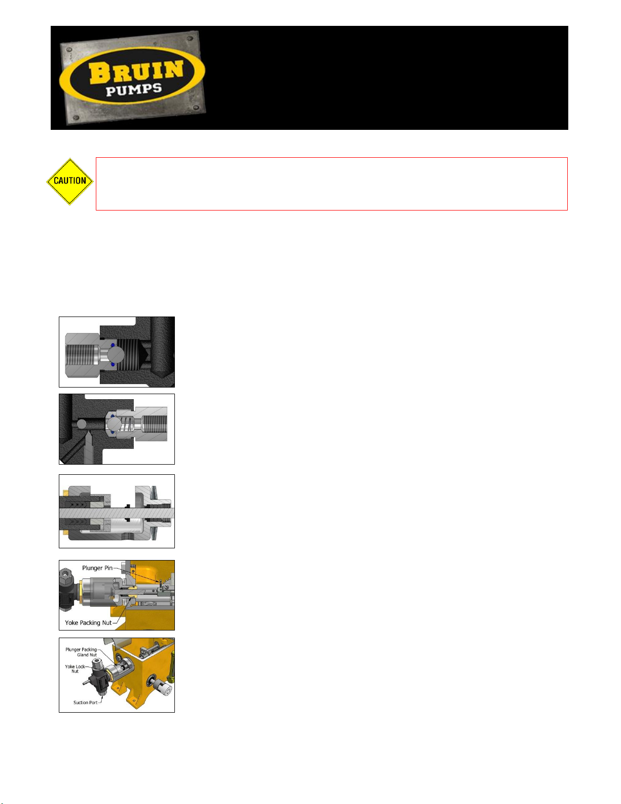
Bruin Pumps BR4300 Installation instructions

MAINTENANCE
Pump Head Maintenance
Pump Head Assembly (3/16” to 1/2” Plunger Size)
Step 1: Ensure all parts are clean and free from damage (see Inspection section). Lubricate all O-rings
with petroleum based lubricant; lubricate packing and plunger with a Teflon or graphite based packing
lubricant.
Step 2: Install O-ring into bottom seat. Place 3/8” ball into bottom seat
(install metal gasket on seat for 3/16” plunger size) and thread seat into
suction end of body utilizing a thread sealant. Tighten bottom seat.
Step 3: Place the 1/4” ball into the discharge end of the body, for plunger
sizes 1/4” to 1/2”. Install O-ring into top seat and insert top seat into body.
Place the 3/8” ball and ball check spring into the top bushing. Thread top
bushing into body, utilizing a thread sealant. Tighten top bushing.
Step 4: Install packing in body, ensuring it is installed in the correct order
and orientation. Note: The “V-Ring” point should be pointing outward. Place
plunger packing gland on the packing. Thread yoke lock nut and yoke onto
the body. Loosely thread plunger packing gland nut onto body. Install plunger
wiper ring and yoke packing set into yoke. Insert plunger into yoke and body
ensuring plunger drip ring is installed on plunger.
Step 5: Thread yoke packing nut into yoke finger tight. Install yoke into
housing with Belleville washers in place. Slide plunger into the adjustment
bolt and insert plunger pin.
Step 6: Orientate body in upright position with suction port down and tighten
yoke lock nut. Snugly tighten the plunger packing gland nut, do not over
tighten.
Step 7: Install gasket and cover with wing screws. Install and tighten priming valve into body.
Maintenance
and Inspection
BR4300
Electric Drive Chemical Injection Pump
Disconnect power source and ensure pressure is removed from pump head prior to
performing any maintenance. Hazardous pressures can result in serious injury or
property damage.
12-19

Pump Head Disassembly (3/16" to 1/2” Plunger Size)
Step 1: Disconnect power source, ensure all pressure is removed from pump head assembly and isolate
fluid discharge and suction lines. Open and remove priming valve. Disconnect fluid discharge
and suction lines.
Step 2: Remove cover and gasket by loosening and removing wing screws.
Step 3: Remove plunger pin from adjustment bolt.
Step 4: Unscrew yoke from housing and remove the pump head assembly from housing.
Step 5: Remove Belleville washers from yoke.
Step 6: Loosen and remove top bushing, ball check spring, balls, and top seat. Remove O-ring from top
seat.
Step 7: Loosen and remove bottom seat and ball. Remove O-ring from bottom seat.
Step 8: Unthread plunger packing gland nut, yoke packing nut and unthread yoke from body. Remove
plunger, plunger packing gland, plunger packing, yoke packing set and plunger drip ring and
wiper ring.
Pump Head Assembly (3/4" and 1” Plunger Size)
Step 1: Ensure all parts are clean and free from damage (see Inspection section). Lubricate all O-rings
with petroleum based lubricant; lubricate packing and plunger with a Teflon or graphite based packing
lubricant.
Step 2: Install O-ring into bottom seat. Place 1/2" ball and gasket onto
bottom seat and cover ball with ball cage. Place gasket (the widest of the four
gaskets) onto ball cage and insert into suction end of body. Thread bottom
bushing into suction end of body utilizing a thread sealant. Tighten bottom
bushing.
Step 3: Install O-ring and retaining ring into top seat. Install top seat into
body with a gasket on both sides of seat. Place 3/8” ball and ball check spring
into top bushing and thread top bushing into body utilizing a thread sealant.
Tighten top bushing.
Step 4: Install packing with lantern ring into body, ensuring packing is
installed in correct order and orientation. Place plunger packing gland on
packing. Loosely thread plunger packing gland nut into body. Insert plunger
into packing and slide plunger drip ring onto plunger.
Step 5: Install plunger wiper ring and yoke packing set into yoke. Insert head
assembly into yoke ensuring plunger fits through yoke. Snugly thread yoke
packing nut into yoke. Attach body and yoke with hex bolts.
Step 6: Install yoke into housing with Belleville washers in place. Slide
plunger into the adjustment bolt and insert plunger pin.

Step 7: Orientate body in upright position with suction port down. Snugly
tighten plunger packing gland nut, do not over tighten.
Step 8: Install gasket and cover with wing screws. Install and tighten priming
valve into body.
Pump Head Disassembly (3/4" and 1” Plunger Size)
Step 1: Disconnect power source, ensure all pressure is removed from pump head assembly and isolate
fluid discharge and suction lines. Open and remove priming valve. Disconnect fluid discharge
and suction lines.
Step 2: Remove cover and gasket by loosening and removing wing screws. Remove plunger pin from
adjustment bolt.
Step 3: Unscrew yoke from housing and remove pump head assembly from housing. Remove Belleville
washers from yoke.
Step 4: Loosen & remove top bushing, ball check spring, ball, gaskets and top seat. Remove retainer
ring and O-ring from top seat.
Step 5: Loosen & remove bottom bushing, bottom seat, ball, ball cage and gaskets. Remove O-ring
from bottom seat.
Step 6: Unthread yoke packing nut. Remove hex bolts and remove yoke from body. Unthread plunger
packing gland nut. Remove plunger, plunger packing gland, plunger packing, lantern ring, yoke
packing set and plunger drip ring and wiper ring.
Housing Maintenance
Housing Assembly
Step 1: Ensure all parts are clean and free from damage (see Inspection section).
Step 2: Place plug and oil gauge assembly into housing, utilizing thread
sealant.
Step 3: Insert lower bearing into housing, ensure roll pin is inserted into
lower bearing and aligned with slot in housing.
Step 4: Slide worm gear into lower bearing. Press bearing stud into gear and
press the crosshead bearing onto the bearing stud with the washer in place.

Step 5: Insert cap screw with lockwasher and bottom thrust washer into
worm gear. Thread cap with O-ring onto lower bearing. Ensure worm gear
rotates freely by hand before proceeding.
Step 6: Press needle bearing into housing.
Step 7: Press inner race bearing and bearing onto worm and shaft assembly.
Install snap rings onto worm and shaft assembly on both sides of bearing.
Step 8: Insert inner snap ring into housing.
Step 9: Insert worm and shaft assembly into housing so that bearing is
positioned into pocket against inner snap ring. Note: To avoid teeth damage,
ensure worm gear teeth mesh properly and walk together as shaft is installed.
Step 10: Install seals into cartridge seal and insert cartridge seal into the
housing pocket, then retain with internal snap ring. Check free rotation of
gears. Insert pipe plug into housing.
Step 11: Place crosshead in correct orientation onto crosshead bearing. Slide
both crosshead guide rods through housing and crosshead.
Step 12: Install O-rings and guide rod retainers. Note: There are 4 of both the
O-rings and rod retainers.
Step 13: Place adjustment bolt through appropriate hole in crosshead. Thread
stroke adjustment gear onto adjustment bolt. Place guide bar onto adjustment
bolt and secure with screw and lockwasher.

Step 14: Place the O-ring on the stroke adjustment spindle and thread the
stroke adjustment knob into the adjustment spindle. Install gasket onto
adjustment spindle and thread into housing. Slide stroke adjustment drive gear
onto stroke adjustment assembly, ensuring that the gear teeth mesh with the
stroke adjustment gear but do not tighten the two set screws on the stroke
adjustment drive gear.
To set the stroke adjustment gears.
Step 15: Rotate the motor coupling by hand until the crosshead is moved as
far as it will go towards the side of the housing on which the head is mounted.
Step 16: Rotate the large gear in the direction that will cause the small gear
to move toward the crosshead and continue rotating it until the small gear is
flush up against the crosshead.
Step 17: Hold the gears in this position to stop rotation and turn the stroke
adjustment knob until it covers the outside groove on the spindle. Adjust the
knob so that the flats on the stem align with the set screws in the adjustment
drive gear and tighten the set screws. The pump is now set in the full
discharge stroke position.
Step 18: Install pump head into housing with Belleville washers. Note: The
suction port is to be orientated down when tight. Insert pin through hole in
adjustment bolt and plunger.
Note: Repeat Steps 13 through 18 for a second head if applicable or install pipe plug into hole in
housing for single headed pumps.
Step 19: Mount gearbox and attach motor with coupling. Refer to Installation
section.
Step 20: Fill the gear box with approximately 1.2 litres of a good grade
lubricant. The oil level should be maintained level with the top of the
crosshead guide rods. For maximum life use an AGMA 7 compounded oil (or
ISO 460 oil). Sample listings of oils are as follows:
Bruin –BPG460-1200
Chevron –Cylinder Oil W 460, Meropa ISO 460, Texaco –Vanguard 460
Mobil –Mobil 600W Super Cylinder Oil, Mobil SHC 634
Petro-Canada –Synduro SHB 460, Enduratex Synthetic EP 460, Enduratex WG 460
Shell –Omala S1 W 460 Summit –Syngear SH-7460
Step 21: Install gasket and cover with wing screws and washer seals.

Housing Disassembly
Step 1: Disconnect power source, ensure all pressure is removed from pump head assembly and isolate
fluid discharge and suction lines. Open and remove priming valve. Disconnect fluid discharge
and suction lines. Drain oil from gear box.
Step 2: Remove wing screws, washer seals, cover and gasket.
Step 3: Remove plunger pin. Remove pump head assembly from housing. See Pump Head Disassembly
instructions for further disassembly of pump head assembly.
Step 4: Loosen both setscrews and remove stroke adjustment drive gear. Remove stroke adjustment
assembly by unscrewing stroke adjustment spindle from housing.
Step 5: Remove all 4 rod retainers and 4 O-rings.
Step 6: Remove both crosshead guide rods by pushing them through crosshead.
Step 7: Remove crosshead assembly from housing. Remove screw, guide bar, stroke adjustment gear
and adjustment bolt from crosshead.
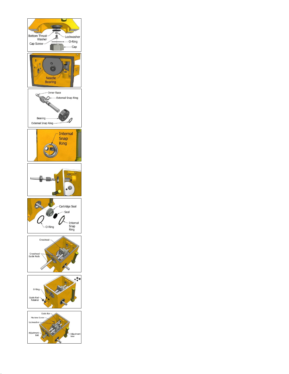
To remove worm gear and shaft.
Step 8: It is not necessary to remove the crosshead assembly in order to remove the worm gear and
shaft.
Step 9: Disconnect coupling and remove motor from base. Note: It is best to remove the entire gear box
from the base.
Step 10: Remove the outside snap ring and pipe plug.
Step 11: Remove worm gear shaft by carefully driving it out from the small end located under the pipe
plug. Be careful not to remove the needle bearing at this time. As the shaft is being driven out,
care should be exercised to ensure that the worm gear is rotating, allowing the gear teeth to
walk and disengage.
Step 12: As the shaft is driven out, it will force out the cartridge seal and ball bearing.
Step 13: Remove the outer snap ring from the shaft and remove the ball bearing.
Step 14: Remove seal from cartridge seal. Note: Removal of seal will result in damage to the seal and
require replacing.
Step 15: Remove needle bearing from housing.
To remove worm gear.
Step 16: Unscrew cap from bottom of housing.
Step 17: Unscrew machine screw from worm gear and remove lockwasher and thrust washer.
Step 18: Remove worm gear from lower bearing. Remove lower bearing from housing.
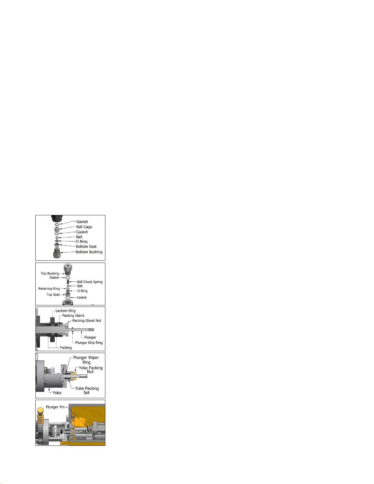
*** *** *** *** ***
INSPECTION
Inspect all components for damage. Replace or repair parts as necessary. The following is a
guideline of what to inspect:
Inspect all threads, seals and packing for damage.
Inspect body seal areas for corrosion, pitting, or damage. Seal areas on the body include the
packing area and the area below the top seat and ball cage.
Inspect balls, top seat, bottom seat and ball check spring for corrosion or damage.
Inspect plunger for wear, scarring, or damage.
Inspect worm gears and bearing for wear or damage.
Inspect housing and all other components for damage.
9001-20 Street NW, Edmonton, Alberta, Canada T6P 1K8 Phone: 780-430-1777 Fax: 780-449-5233
Table of contents
Other Bruin Pumps Water Pump manuals