EN
5 - INSTALLATION
5.1 - Preliminary checks and positioning the pump
Make sure the pump has not been damaged while being transported or stored.
Remove any remaining packaging material from the product (e.g. protective caps) and carefully clean the suction and
discharge outlets.
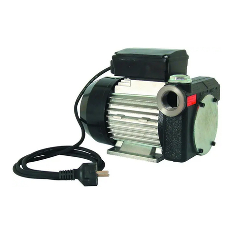
Install the pump in any position (pump axis either horizontal or vertical), in a place sheltered from rain and weather events.
Position and fix the pump with screws that are suitably sized for the holes on the motor flange. The best performance in terms
of noise and vibration reduction is achieved by placing 4 vibration dampers of suitable height between the pump and the base.
For the centre distances of the holes, see section 7.1 - Overall dimensions and weights.
5.2 - Hydraulic pipe connection
Before connecting the pump, make sure the tank, fittings and pipes used are clean and free from waste or processing residues.
Before connecting the discharge pipe to the pump, we recommend partially filling the pump body with diesel fuel to lubricate
and facilitate the priming procedure.
CAUTION! The motors are not explosion-proof. They must not be installed in areas with
flammable vapours or open flames.
CAUTION! Do not use couplings or connection fittings with conical threading, as these
could damage the pump coupling outlets if tightened too much.
We recommend using ADAM PUMPS suction and discharge pipes, which are designed specifically for the pump in use;
alternatively, respect the dimensions and specifications in the table below.
PB 50 12 V, PB 50 24 V, PB1 50 12 V, PB1 50 24 V, PB 60 12 V, PB 60 24 V, PB1 60 12 V, PB 1 60 24 V PB 85 12 V, PB 85 24 V, PB1 85 12 V, PB1 85 24 V
Suction Discharge Suction Discharge
Pump inlet connection thread 1" G - BSP 1" G - BSP 1" G - BSP 1" G - BSP
Recommended minimum internal diameters ø25 mm ø19 mm ø25 mm ø25 mm
Recommended rated pressure 10 Bar 10 Bar 10 Bar 10 Bar
Pipe suitable for operation under negative pressure • •
5.3 - Remarks on the suction lines
SUCTION
LINE
The electric pumps in this manual are self-priming and can draw the liquid from a maximum height of 2 metres.
Caution, proper priming and the time required for this can be affected by an automatic nozzle on the discharge
line, which prevents normal air extraction from the pipe. It is therefore always advisable to prime the pump for
the first time without the automatic nozzle and with the discharge pipe emptied from the liquid. To facilitate the
subsequent start-up operations of the pump so that they are immediate, it is always recommended to install a
foot valve to prevent the suction pipe from emptying and to keep the pump wet. When the system is in operation,
the pump can work with negative pressure at the suction inlet up to 0.5 Bar, after which cavitation phenomena
can start with consequent reduction of the flow rate and increase in noise. To prevent this phenomenon from
occurring it is important to ensure low suction negative pressure, by using short pipes or pipes with a diameter
larger than or the same as those recommended, minimising bends and using large section suction filters and
foot valves with the least resistance possible. Moreover, it is very important to keep all suction filters clean to
prevent the system resistance from increasing when they are clogged.
DISCHARGE
LINE
The electric pump must be chosen based on the system’s specifications. Incorrect combinations of the length of
the pipe, of its diameter, of the flow rate of the diesel fuel and/or of the accessories installed on the line, can cre-
ate a counterpressure on the discharge line that is higher than the maximum set and so cause the pump bypass
to open (partially) with consequent reduction in the flow rate dispensed. To prevent this from happening and
allow the pump to work properly, the system resistance has to be reduced using pipes that are shorter and/or
with a larger diameter and line accessories with less resistance (e.g. an automatic nozzle for greater flow rates).


