Brunswick I-26 User manual

I-26/26R
Large Stackable
Incubator Shakers
MANUAL NO: M1324-0050
Revision B
March 15, 2006
NEW BRUNSWICK SCIENTIFIC CO., INC.
BOX 4005 •44 TALMADGE ROAD •EDISON, NJ 08818-4005
Telephone: 1-732-287-1200 •1-800-631-5417
Fax: 732-287-4222 •Telex: 4753012 NBSCO

ii
I-26/26R Incubator Shakers M1324-0050 User’s Guide

iii
New Brunswick Scientific Co., Inc. User’s Guide
INTERNATIONAL OFFICES:
BELGIUM
New Brunswick Scientific NV-SA
Stationsstraat 180/4
3110 Rotselaar
België/Belgique
Tel: 32 (0)16 56 28 31
Fax: 32 (0)16 57 27 53
GERMANY
New Brunswick Scientific GmbH
In Der Au 14
D-72622 Nürtingen
Deutschland
Tel: 49 (0)7022 932490
Fax: 49 (0)7022 32486
CHINA
New Brunswick Scientific Co., Inc.
A903, 904 Yin Hai Building
No. 250, Cao Xi Road
Shanghai 200235, P.R. China
Tel: 86 21 6484 5955 or 5966
Fax: 86 21 6484 5933
THE NETHERLANDS
New Brunswick Scientific BV
Kerkenbos 1101, 6546 BC Nijmegen
P.O Box 6826, 6503 GH Nijmegen
Nederland
Tel: 31 (0)24 3717 600
Fax: 31 (0)24 3717 640
FRANCE
New Brunswick Scientific SARL
12-14, Rond Point des Champs Elysées
75008 Paris
France
Tel: 33 (0)1 5353 1511
Fax: 33 (0)1 5353 1557
UNITED KINGDOM
New Brunswick Scientific (UK) Ltd.
17 Alban Park
St. Albans, Herts. AL4 0JJ
United Kingdom
Tel: 44 (0)1727 853855 or 0800 581331
Fax: 44 (0)1727 835666
Web: www.nbsuk.co.uk

iv
I-26/26R Incubator Shakers M1324-0050 User’s Guide
CAUTION!
This equipment must be operated as described in this manual.
If operational guidelines are not followed, equipment damage and
personal injury can occur.
Please read the entire User’s Guide before attempting to use this unit.
Do not use this equipment in a hazardous atmosphere or with
hazardous materials for which the equipment was not designed.
New Brunswick Scientific Co., Inc. (NBS) is not responsible for any
damage to this equipment that may result from the use of an
accessory not manufactured by NBS.

v
New Brunswick Scientific Co., Inc. User’s Guide
Copyright Notice
New Brunswick Scientific Company, Inc.
Box 4005 44 Talmadge Road
Edison, New Jersey 08818-4005
©Copyright 2006 New Brunswick Scientific Co., Inc.
All Rights Reserved.
Reproduction, adaptation, or translation without prior written permission from
New Brunswick Scientific is prohibited.
Disclaimer Notice
New Brunswick Scientific Co., Inc. reserves the right to change
information in this document without notice. Updates to information in this
document reflect our commitment to continuing product development and
improvement.
Manual Conventions
NOTE: Notes contain essential information that deserves
special attention.
CAUTION!
CAUTION messages appear before procedures
which, if caution is not observed, could result in
damage to the equipment.
WARNING! WARNING messages alert you to specific
procedures or practices which, if not followed
correctly, could result in serious personal injury.
Bold Text in bold face type emphasizes key words or
phrases.
CRUSH WARNING!
Crush Warning messages alert you to specific
procedures or practices regarding heavy objects
which, if not followed correctly, could result in
serious personal injury.

vi
I-26/26R Incubator Shakers M1324-0050 User’s Guide
Every instrument manufactured by
New Brunswick Scientific Co., Inc. is warranted
to be free from defects in material and workmanship.
This apparatus is warranted for 2 years’ material and labor
against faulty components and assembly. Our obligation
under this warranty is limited to repairing or replacing the
instrument or part thereof which shall, within 2 years after the date
of shipment, prove to be defective upon our examination. This
warranty does not extend to any NBS products which have
been subjected to misuse, neglect, accident or improper
installation or application; nor shall it extend to
products which have been repaired or altered
outside the New Brunswick Scientific
factory without prior authorization
from NBS.
W A R R A N T Y

vii
New Brunswick Scientific Co., Inc. User’s Guide
TABLE OF CONTENTS
1OVERVIEW.....................................................................................................................................................9
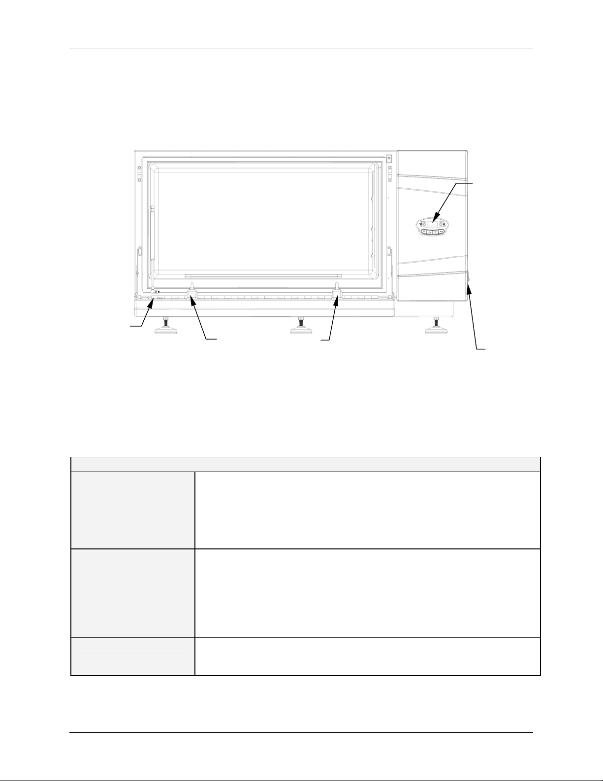
1.1 FRONT VIEW ...........................................................................................................................................10
1.2 SPECIFICATIONS ......................................................................................................................................10
1.3 CERTIFICATIONS......................................................................................................................................11
2INSPECTION, VERIFICATION & UNPACKING OF EQUIPMENT...................................................13
2.1 INSPECTION OF BOXES.............................................................................................................................13
2.2 PACKING LIST VERIFICATION..................................................................................................................13
2.3 UNPACKING OF EQUIPMENT ....................................................................................................................13
3PREPARING THE LOCATION..................................................................................................................14
3.1 PHYSICAL LOCATION...............................................................................................................................14
3.2 ENVIRONMENT ........................................................................................................................................14
3.3 ELECTRICAL REQUIREMENTS ..................................................................................................................14
3.4 SPACE REQUIREMENTS............................................................................................................................14
4INSTALLING THE I-26/26R.......................................................................................................................16
4.1 TOOLS REQUIRED FOR INSTALLATION.....................................................................................................16
4.2 LEVELING A SINGLE SHAKER ..................................................................................................................16
4.3 ADDING A BASE ......................................................................................................................................17
4.4 PREPARING THE OPTIONAL BASE ............................................................................................................17
4.5 MOUNTING THE I-26/26R ON THE OPTIONAL BASE.................................................................................19
4.6 INSTALLING THE I-26/26R STACKING KIT...............................................................................................21
4.7 STACKING THE I-26/26R .........................................................................................................................22
4.8 STACKING A THIRD I-26/26R..................................................................................................................23
4.8.1 Load and Speed Graphs ....................................................................................................................23
5FEATURES....................................................................................................................................................25
5.1 KEYPAD ..................................................................................................................................................25
5.2 LED DISPLAY .........................................................................................................................................25
5.3 USER INTERFACE KEYS...........................................................................................................................26
5.4 STATUS INDICATORS ...............................................................................................................................26
5.5 FUNCTION INDICATORS ...........................................................................................................................27
6GETTING STARTED...................................................................................................................................28
6.1 PLATFORM ASSEMBLIES..........................................................................................................................28
6.2 INSTALLATION OF CLAMPS......................................................................................................................28
6.3 INSTALLING/SLIDING OUT PLATFORM .....................................................................................................29
6.4 ELECTRICAL CONNECTIONS ....................................................................................................................30
7OPERATION .................................................................................................................................................32
7.1 STARTING THE SHAKER...........................................................................................................................32
7.2 CONTINUOUS (UNLIMITED) RUN.............................................................................................................33
7.3 CHECKING ANY SETPOINT.......................................................................................................................33
7.4 TIMED FUNCTIONS ..................................................................................................................................33
7.5 ALARM FUNCTIONS.................................................................................................................................34
7.6 TEMPERATURE SETPOINT ........................................................................................................................35
7.7 TEMPERATURE OFFSET CALIBRATION.....................................................................................................35
7.8 POWER FAILURE......................................................................................................................................36

viii
I-26/26R Incubator Shakers M1324-0050 User’s Guide
7.9 SPEED CALIBRATION...............................................................................................................................36
7.10 TILT SWITCH ...........................................................................................................................................37
8PREVENTIVE MAINTENANCE................................................................................................................38
8.1 CLEANING EXTERNAL SURFACES............................................................................................................38
8.2 FUSE REPLACEMENT ...............................................................................................................................38
8.3 BELT REPLACEMENT ...............................................................................................................................41
9SERVICE........................................................................................................................................................44
9.1 TROUBLESHOOTING.................................................................................................................................44
9.2 REPLACEMENT PARTS .............................................................................................................................45
9.3 ACCESSORIES ..........................................................................................................................................46
9.3.1 Available Platforms...........................................................................................................................46
9.3.2 Flask Clamps for Universal Platforms..............................................................................................46
9.3.3 Replacement Clamp Hardware Kits..................................................................................................46
9.3.4 Carriers and Test Tubes ....................................................................................................................47
9.3.5 Optional Bases for I-26/26R..............................................................................................................47
9.3.6 Stacking Kit for I-26/26R...................................................................................................................48
9.3.7 Optional Handles...............................................................................................................................48
10 DRAWINGS...................................................................................................................................................49
10.1 CONTROL SCHEMATICS ...........................................................................................................................49
10.2 LIST OF DRAWINGS .................................................................................................................................53
11 INDEX.............................................................................................................................................................54

9
New Brunswick Scientific Co., Inc. User’s Guide
1
1
O
OV
VE
ER
RV
VI
IE
EW
W
The I-26/26R large stackable incubator shakers are large capacity orbital shakers that
utilize a triple eccentric counter-balanced drive mechanism. They provide horizontal
plane rotary motion in a 1-inch (2.54 cm) diameter circular orbit. A Proportional /
Integral (PI) microprocessor controller with instantaneous digital feedback controls the
speed over a range of 25-400 rpm.
The I-26 provides temperature control from 5°C above ambient to 60°C. The refrigerated
I-26R assures temperature control down to 15°C below ambient, with a minimum
setpoint of 4°C. Ambient temperature is measured one meter from the front of the unit.
The shakers may be operated either continuously or in a timed mode via a programmable
timer for shaking periods of 0.1 to 99.9 hours.
For safe operation, the I-26/26R models are designed with a safety switch that
automatically stops the shaker mechanism when the door is opened.
The I-26/26R is equipped with visual and audible alarms that alert the user to the
following conditions:
• The end of a timed run
• Deviations from speed setpoint
• Deviations from temperature setpoint
• Power failure
• Door open
• Unstable operating conditions (tilt switch—visual alarm only)
A wide variety of slide-out platforms can be used with the I-26/26R. Dedicated
platforms and universal platforms are available for a variety of flask sizes. Test tube
racks, microtiter plate holders, and test tube rack holders are also available (a universal
platform is needed for all test tube racks and holders). For further information on these
accessories, see Section 9.3.

10
I-26/26R Incubator Shakers M1324-0050 User’s Guide
1.1 Front View
This drawing is for reference, to acquaint you with the user interface controls:
Figure 1: Front View
1.2 Specifications
These specifications assume a maximum load of 34 pounds (15.5 kg), including
platforms, clamps, glassware and contents.
I-26/26R Incubator Shaker
SHAKING
Speed
Control Accuracy
Indication
Stroke/Orbit
Single unit: 25-400 rpm
2 or 3 units stacked: 25-250 rpm
±1 rpm
3 Digit LED, in 1 rpm increments
1-inch (2.5 cm)
TEMPERATURE
I-26 Range
I-26R Range
Control Accuracy
Indication
Heaters
5°C above ambient temperature to 60°C
15°C below ambient (minimum 4°C) to 60°C
±0.1°C from 30-40 °C, ±0.5°C over the remaining range.
3 Digit LED, in 0.1°C increments
Long-life, low-watt density resistance-type heaters with high
temperature thermostats
ALARMS Visible and audible warning indication when speed deviates more
than 5 rpm or temperature more than 1°C from setpoints, and when
timer has expired. Audible alarm can be muted.
...continued...
ON/OFF
Switch
USER
INTERFACE
(display,
indicator
lights &
keypad)
NOTE:
Door is open PLATFORM RESTS
on back of door

11
New Brunswick Scientific Co., Inc. User’s Guide
I-26/26R Incubator Shaker
LED DISPLAY Indicates speed, temperature, running time alarm conditions, and
displays readout of internal clock (actual accumulated operating
time). Character height: 9/16 inches (14.3 mm)
RS 232 Provides access for remote data logging
SETPOINT
RETENTION All setpoints and operating status are retained in non-volatile
memory
AUTOMATIC
RESTART Automatic restart after power is restored, indicated by flashing
display
STACKING Up to three units may be stacked; the second and third units require
stacking kit(s).
DRIVE Triple-eccentric counterbalanced drive with nine permanently
lubricated ball bearings
DRIVE MOTOR Solid-state brushless DC motor.
SAFETY An independent mechanical sensing “tilt switch” shuts off the motor
in an unbalanced condition. Drive Interrupt shuts off power to shaker
when door opens. Acceleration/deceleration circuit prevents sudden
starts and stops, minimizing both splashing and mechanical
damage.
ELECTRICAL
REQUIREMENTS 100 Volts, 50/60 Hz
120 Volts, 60 Hz
230 Volts, 50 Hz
I-26: 800 VA per shaker
I-26R: 1500 VA per shaker
ETL REGULATORY
STANDARDS UL61010A-1
UL61010A-2-010 CAN/CSA-C22.2 No 1010.1
CAN/CSA-C22.2 No 1010.2.010
CE REGULATORY
STANDARDS See DECLARATION OF CONFORMITY
OVERALL
DIMENSIONS
Width
Depth (Front to Back)
Height
Single Unit
50" (127 cm)
30.26" (77 cm)
27.56" (70 cm)
Two Units
50" (127 cm)
30.26" (77 cm)
52.62" (140 cm)
Three Units
50" (127 cm)
30.26" (77 cm)
77.68" (210 cm)
CHAMBER
DIMENSIONS 34” (86.4 cm) W X 23” (58.4 cm) D X 15.5" (39.4 cm) H clearance
above platform
PLATFORM Aluminum, 18" X 30" (46 X 76 cm)
WEIGHT I-26: 370 pounds (167.8 kg)
I-26R: 400 pounds (181.5 kg)
FUSES Two 8.0A 250V, Slo-Blo®
1.3 Certifications
The I-26 and I-26R have been tested to ETL standards, to comply with UL and
CAN/CSA electrical safety standards (see “ETL Regulatory Standards” in the
specifications table). As attested in the CE Declaration of Conformity reproduced on the
following page, they also conform to the appropriate CE standards.

12
I-26/26R Incubator Shakers M1324-0050 User’s Guide

13
New Brunswick Scientific Co., Inc. User’s Guide
2
2
I
IN
NS
SP
PE
EC
CT
TI
IO
ON
N,
,
V
VE
ER
RI
IF
FI
IC
CA
AT
TI
IO
ON
N
&
&
U
UN
NP
PA
AC
CK
KI
IN
NG
G
O
OF
F
E
EQ
QU
UI
IP
PM
ME
EN
NT
T
2.1 Inspection of Boxes
After you receive your order from New Brunswick Scientific, inspect the boxes carefully
for any damage that may have occurred during shipping. Report any damage to the
carrier and to your local NBS Sales Order Department.
2.2 Packing List Verification
Verify against your NBS packing list that you have received the correct materials.
2.3 Unpacking of Equipment
CRUSH WARNING!
Do not attempt to lift the I-26/26R by hand.
Always use a lifter or other suitable equipment when raising or handling
the unit.
To unpack your I-26/26R, you will need the following:
• Hammer
• Forklift or other lifting equipment to lift 370 lbs (168 kg) or more
• Shears to cut ½-inch (12.7 mm) wide plastic strapping
• Tool to remove 3-inch (7.6 cm) metal staples
Save all packing materials and the Operating Manual. If any part of your order was
damaged during shipping, is missing pieces, or fails to operate properly, please fill out
Customer Satisfaction Form 6300 and return it by fax.

14
I-26/26R Incubator Shakers M1324-0050 User’s Guide
3
3
P
PR
RE
EP
PA
AR
RI
IN
NG
G
T
TH
HE
E
L
LO
OC
CA
AT
TI
IO
ON
N
3.1 Physical Location
It is essential that the instrument be situated in an area where there is sufficient space for
the shaker and platform to clear walls and obstructions during operation. The surface on
which the unit is placed must be smooth, level, and able to support the shaker under full
load operating conditions.
CRUSH WARNING!
Do not attempt to lift the I-26/26R by hand.
Always use a lifter or other suitable equipment when raising or handling
the unit.
3.2 Environment
The shaker is designed to operate optimally in the following ambient conditions:
• 5º to 35°C
• 20 to 80% Relative Humidity non-condensing
3.3 Electrical Requirements
100, 120 or 230 VAC (depending on your selection)
800 VA for each I-26, 1500 VA for each I-26R
3.4 Space Requirements
(See Figure 1a on the following page.)

15
New Brunswick Scientific Co., Inc. User’s Guide
Figure 1a: Dimensions
Be sure to allow four inches (10 cm) around the shaker for proper ventilation, and 24
inches (61 cm) on the right side for service access to fan and refrigeration assemblies.
WIDTH: 50 inches
127 cm
HEIGHT:
27.6 inches
77 cm
DEPTH:
30.3 inches
70 cm
DOOR
EXTENSION:
22.5 inches
57 cm
DOOR WIDTH:
39 inches
57 cm

16
I-26/26R Incubator Shakers M1324-0050 User’s Guide
4
4
I
IN
NS
ST
TA
AL
LL
LI
IN
NG
G
T
TH
HE
E
I
I-
-2
26
6/
/2
26
6R
R
CRUSH WARNING!
Do not attempt to lift the I-26/26R by hand.
Always use a lifter or other suitable equipment when raising or handling
the unit.
4.1 Tools Required for Installation
To install the I-26/26R on an optional base and/or to stack I-26/26R units, the following
tools will be needed:
• Number 2 Phillips head screwdriver
• Level, ≥10-inch (25.4 cm)
• Two adjustable wrenches
• Forklift or other lifting equipment to lift more than 370 lbs (168 kg)
• Metal leveling shims
4.2 Leveling a Single Shaker
NOTE:
Do NOT use feet if you are stacking shakers or adding a base.
Make sure that the shaker is placed on a level surface and that all four feet are solidly on
the surface. If the shaker is not level, adjust the feet as needed to achieve leveling:
1. Immobilize the top lock nut against the unit with one wrench whenever you adjust
the foot, to keep the threaded stud from falling out.
Figure 2: Adjustable Foot
BOTTOM
OF UNIT
LOCK NUT
FLATS FOR WRENCH
FOOT

17
New Brunswick Scientific Co., Inc. User’s Guide
2. With a second wrench against the flats of the threaded stud, just above the foot:
rotate clockwise to lower the foot or counter-clockwise to raise the foot.
3. Place a level on the top of the unit.
4. If necessary, make further adjustments by repeating all steps until the unit is level.
5. Fully load the shaker and do a test run at normal speed. Make additional leveling
adjustments if necessary.
NOTE:
The maximum foot height adjustment is ~ ¼ inch (6.4 mm). If a higher
adjustment is required, you will need to add metal shims.
4.3 Adding a Base
There are three bases available for your I-26/26R shaker(s). The height of the base
depends on whether you are installing one unit on the base, or stacking two or three units:
Table 1: Optional Bases
Number of Shakers Base Height
1 17 inches (43.2 cm)
One 4-inch base & one 13-inch base,
bolted together at the factory
2 stacked 13 inches (33.0 cm)
3 stacked 4 inches (10.2 cm)
4.4 Preparing the Optional Base
1. Place the base on a sturdy (capable of bearing the weight of the combined base
shakers and shaker contents), level surface, making sure that all four corners are
solidly on the surface.
2. If the base is not level, place metal shims as needed under the base until it is level.
3. If you are mounting a single shaker, use the 17-inch base as shown in Figure 3b. Bolt
the shaker to the base using the hardware provided.

18
I-26/26R Incubator Shakers M1324-0050 User’s Guide
Figure 3a: Optional 4-inch Base
Figure 3b: Optional 17-inch Base
4. As shown in Figures 3a-b, depending on the height of your base, install the front side
braces and rear corner braces on the base with the hardware provided, matched to the
holes in the base.
REAR CORNER
BRACE
FRONT SIDE
BRACE
13-INCH BASE
4-INCH BASE
BASE MATING SUPPORTS

19
New Brunswick Scientific Co., Inc. User’s Guide
4.5 Mounting the I-26/26R on the Optional Base
1. Using a forklift or lifter, raise the I-26/26R so that its back end is tilted toward the
rear of the base.
2. Remove all six feet from the bottom of the shaker. They will not be needed for
stacking, but you may want to keep them for future use.
3. With two assistants, each holding the shaker on one side, lower the unit onto the base,
rear panel first. Slowly and gently remove the forklift or lifter and lower the front of
the unit onto the base by hand.
NOTE:
Optional handles are available to facilitate maneuvering the shaker onto the
base. See Section 9.3.7 for details.
Figure 4: Mounting Shaker on Base
4. Using the ½-13 x 1¼-inch Allen head screws, ½-inch lock washers, and washers
provided, secure the rear of the I-26/26R to the corner braces in the base. With the
remaining ½-13 x 1¼-inch Allen head screws, ½-inch lock washers, and washers,
attach the front corner braces to the unit.
5. Attach the front corner braces to the base using the two sets of ½-13 x 1¼-inch Allen
head screws, lock washers, and washers provided, and secure as shown in Figure 5.

20
I-26/26R Incubator Shakers M1324-0050 User’s Guide
Figure 5: Mounting Corner Braces
With the corner braces securely in place, the shaker mounted on its base will look like
this:
Figure 6: Shaker Installed on Base
6. Make sure the shaker is level; add metal shims under the base as needed to level the
unit.
7. Fully load the shaker and do a test run at normal speed. Make additional leveling
adjustments if necessary.
This manual suits for next models
1
Table of contents
Other Brunswick Accessories manuals
Popular Accessories manuals by other brands

Invacare
Invacare Personal Seat VF Installation and operating instructions

TMT Automation
TMT Automation ChowBELL2 Pro user manual

Omron
Omron D6T Series user manual

Orno
Orno SOUL DC Operating and instalation instructions

Digital reasures
Digital reasures PowerNow! 10000+ user guide

turck
turck FCS-GL1/2A4-NAEX0-H1141 manual