Brunswick Authority22 User manual

Authority22 Graphic User Interface will not turn on.
Symptom #1: Graphic User Interface (GUI) display will not come on, nor will the Red LED on the
keypad come on. “No Power to the GUI”
Symptom #2: Sometimes a “Power Lost” message will be shown on the display and the red LED will
be blinking (“Power Lost” troubleshooting is near the bottom of this document)
What the “Power Lost” message means:
This means there has been an interruption or loss of power to the GUI. It had lost power during operation from
a loose connection or a voltage drop from the machine. You will see this message on the GUI screen and the
Red LED is lit and flashing on the keypad under normal conditions.
Note: Before starting any troubleshooting below, Is the emergency stop button depressed? Push down on the
emergency stop button, then turn the red knob and let it pop back up to the on position. Are any of the
breakers tripped? Is there still no power to the GUI? The GUI has a red LED in the keypad that will light when
power is applied.
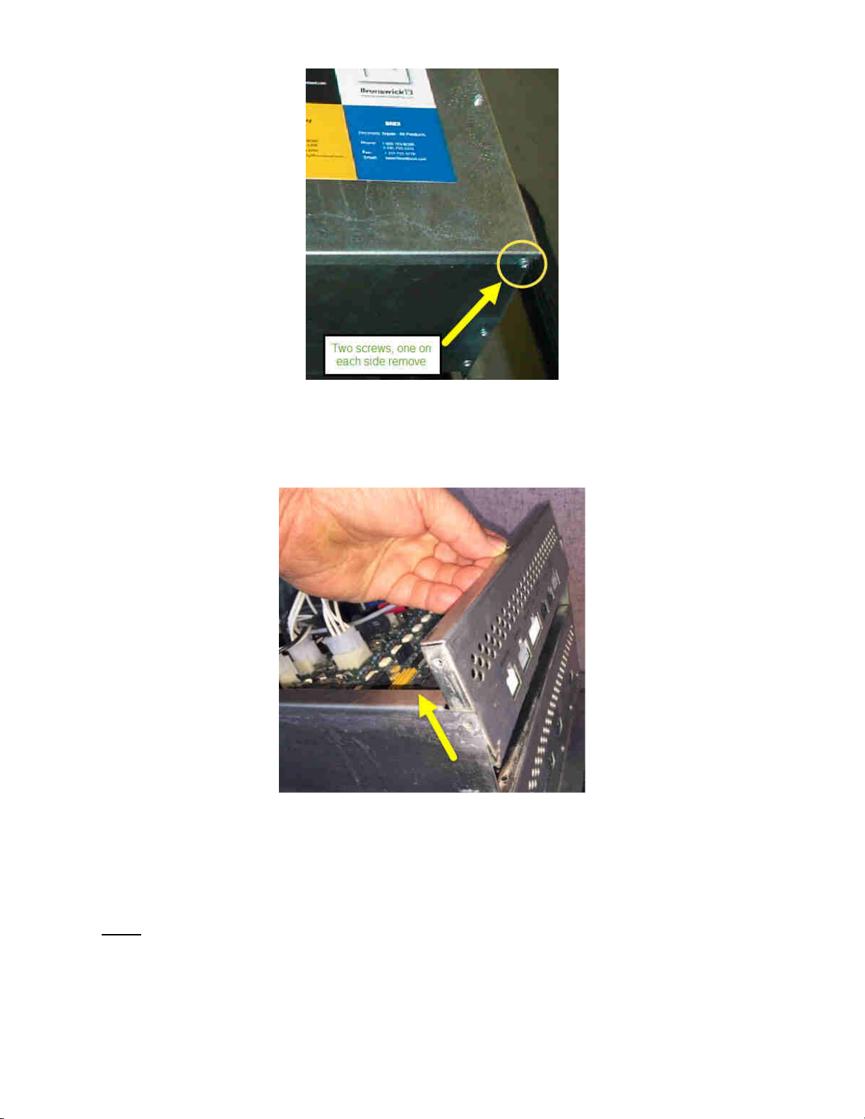
If not, remove the GUI and test your GUI with the external power supply from you spare parts kit to see if the
GUI can be powered up. If you use the external power supply to power up the GUI, and the GUI does in fact
power up and boot to the operating screen, then follow the procedures below.
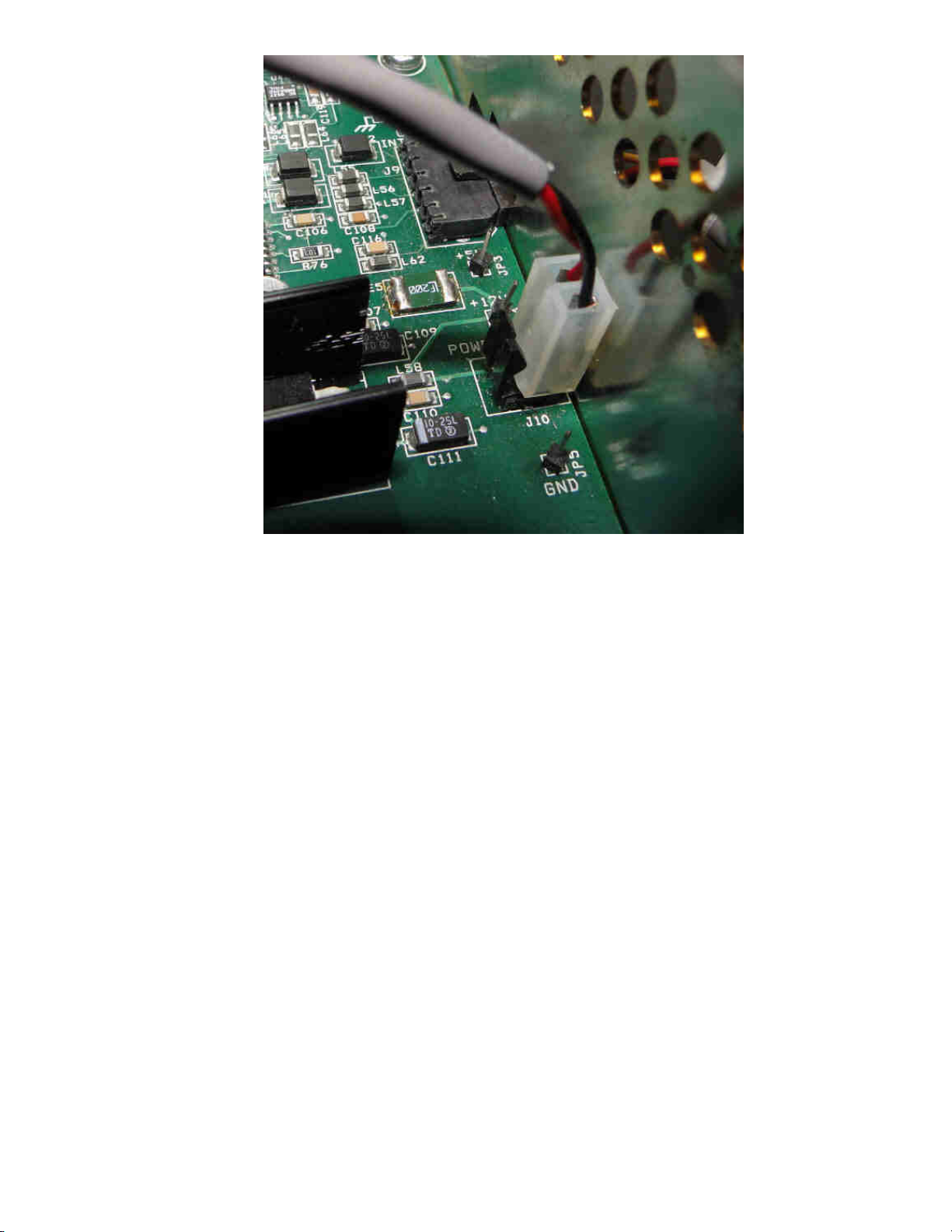
If the GUI does not power up the UPS inside the GUI could have failed or there is a broken terminal on the
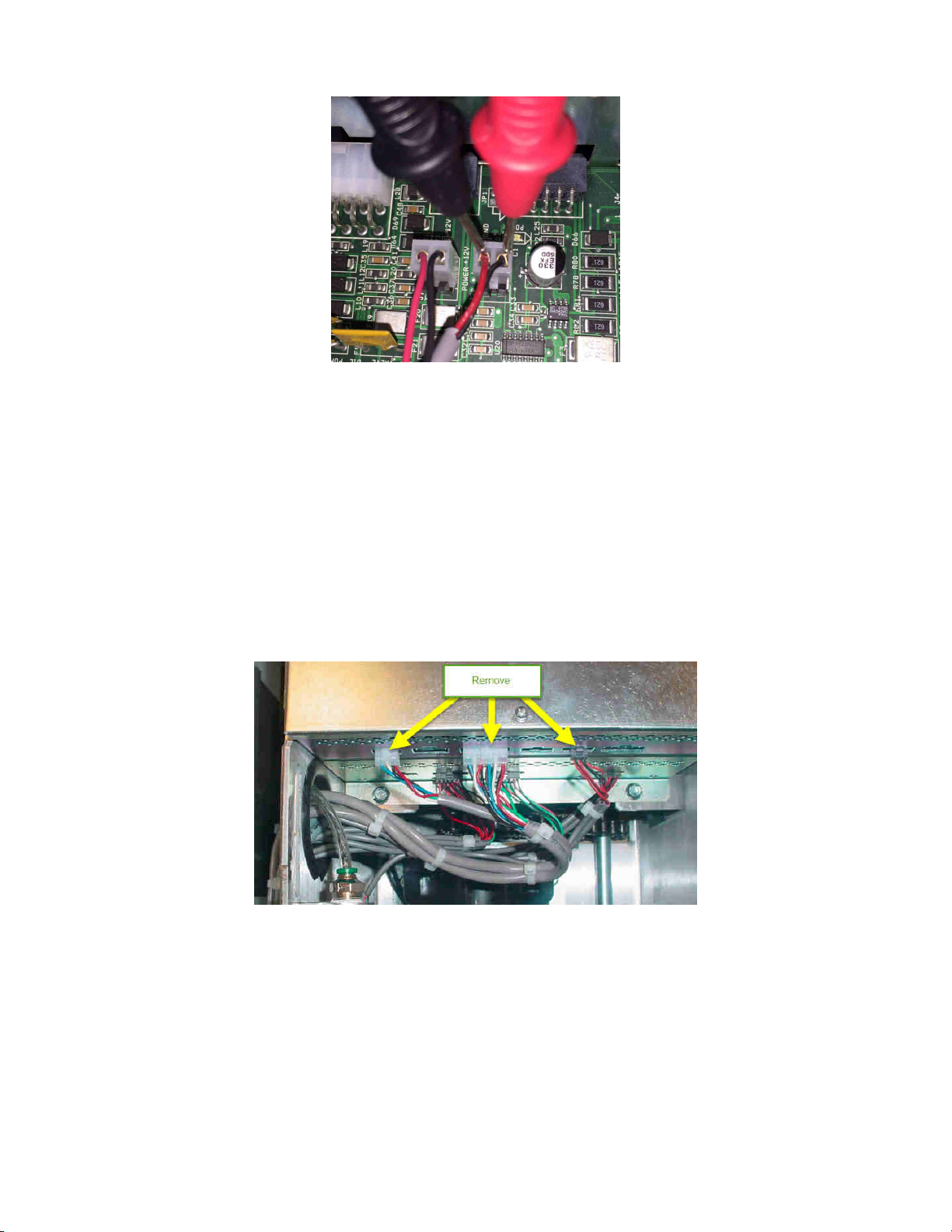
UPS board. Open the cover of the GUI and remove the mid plate to check connections and wiring. If after
checking the wiring and the GUI still does not turn on replace the UPS or GUI. Electronic Repair Center part
number for the UPS is # 14-100177-800 and the part number for the GUI is # 14-100362-800
Troubleshooting “No Power to the GUI”.
#1 Is the power cord plugged in and the main power switch on the Electrical Enclosure turned on? If so,
see step #2
#2 Is the emergency stop button depressed or wiring disconnected?
•Press down on the emergency stop button and turn it so it pops back up to make sure it is up
and on.
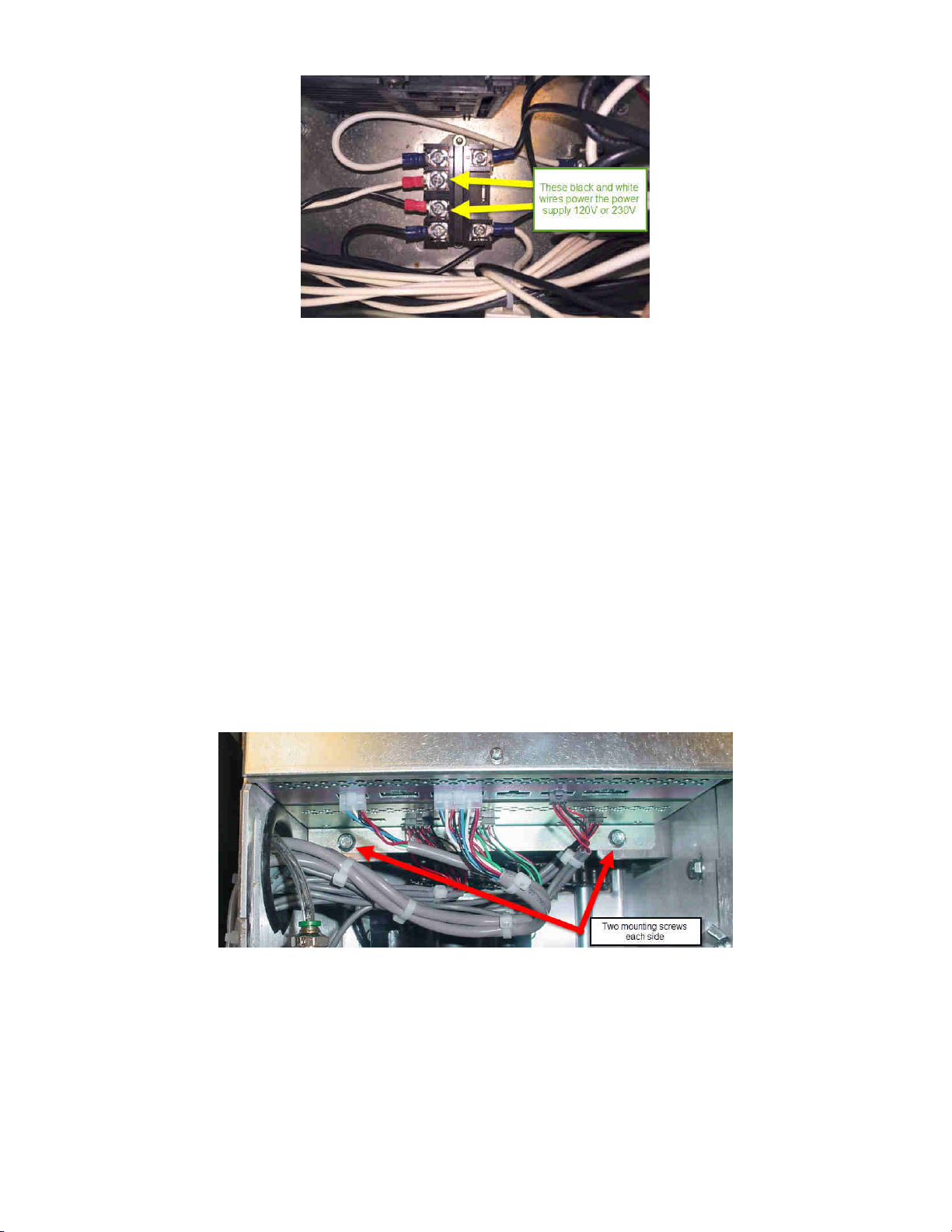
•We have seen the bottom part of this emergency stop switch come loose on the inside of the
electrical enclosure, be sure to open the cover and check this connection.
•If the emergency stop switch is good see step #3
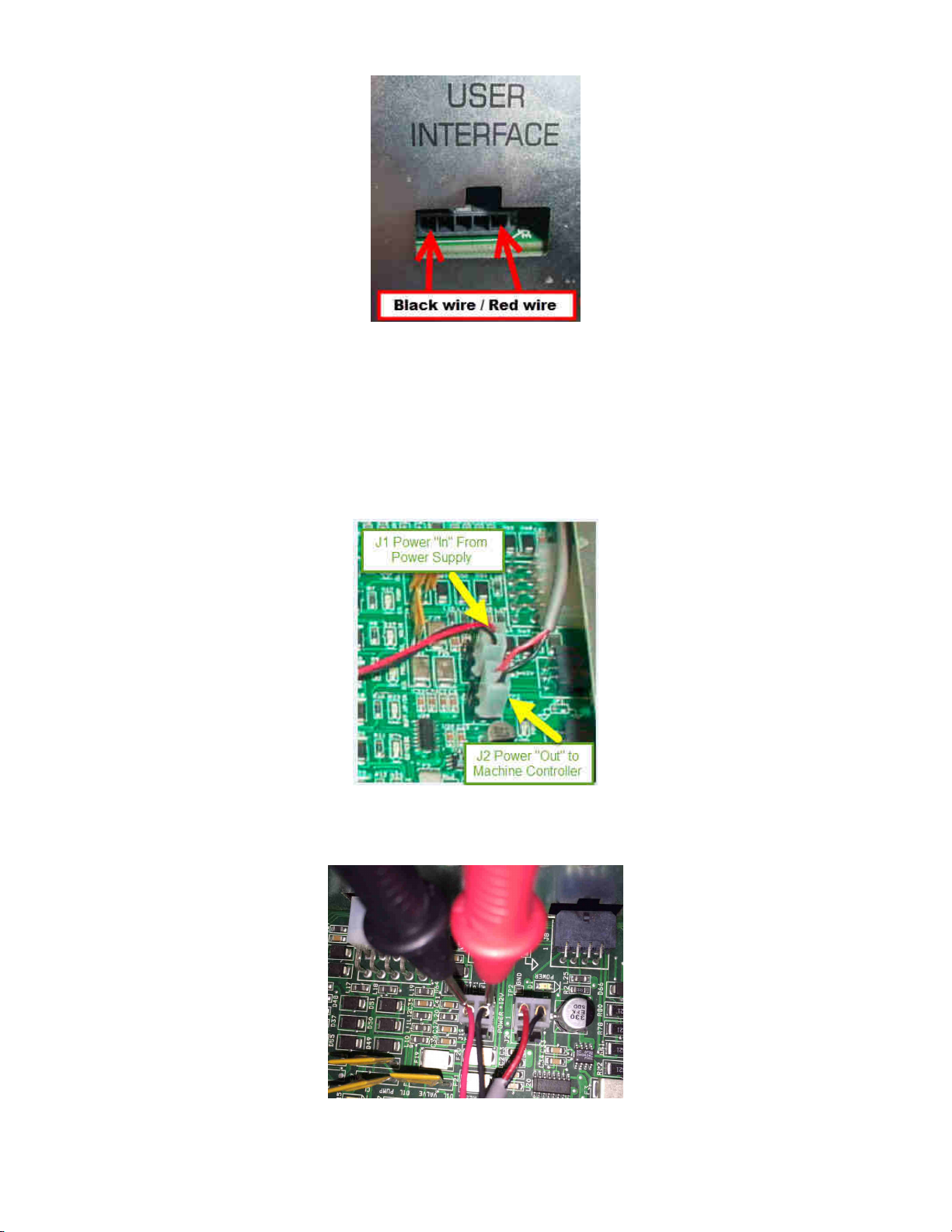
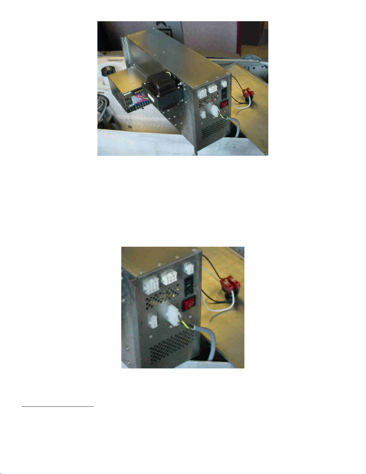
#3 Is the Power/Communication cable from the electrical enclosure to the GUI plugged in to the back of
the GUI and plugged into the electrical enclosure located on the RH side looking from the T handle
named “User Interface”?
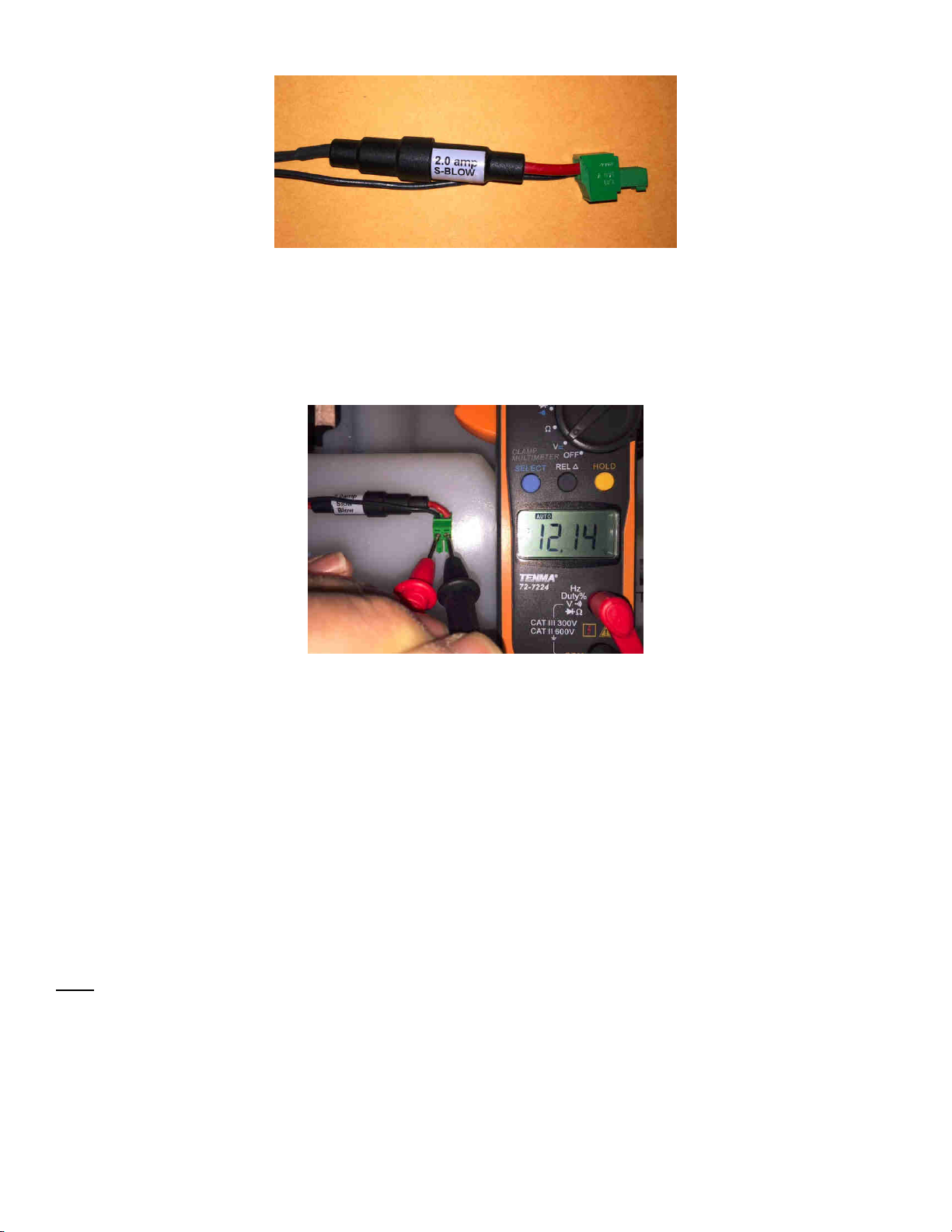
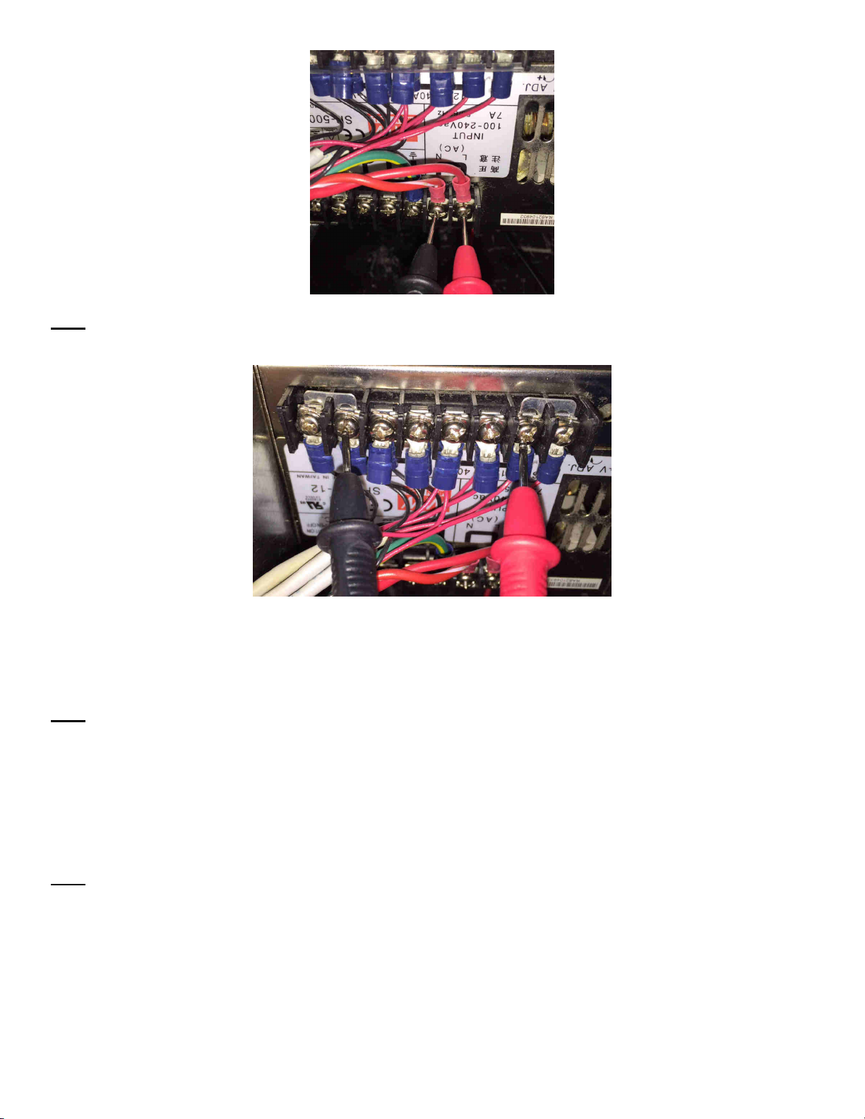
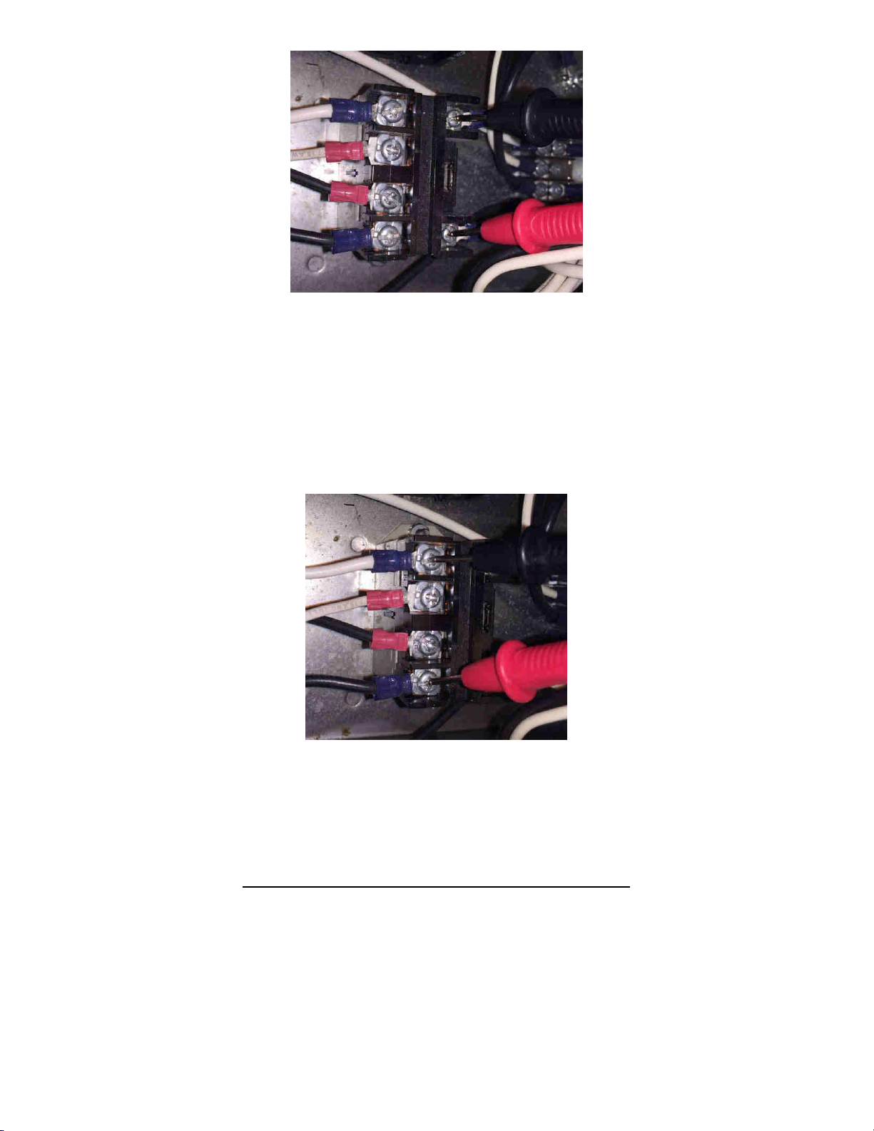
Note: The newer power cables have fuse holders in the red power line near the connector for the GUI
as shown below in Figure #1. There is a 2-amp slow blow fuse in this line, is it blown? Verify with a
voltmeter.

Figure #1
•To test for 12 VDC to the GUI, unplug the green power connector to the back of the GUI, using
a digital volt meter set it for DC Volts, put one lead on each of the set screws like in the picture
below Figure #2
Figure #2
•If there is 12 VDC power to the end of this cable, and there is both no Red LED or the display is
not on, then the GUI UPS power terminals may have been broken from the solder joint, or the
UPS itself has failed, or the GUI itself has failed. The part number for the UPS from the
electronic repair center is # 14-100177-800 or the GUI assembly 14-100362-800.
•If there is no 12 VDC at this connection, see step #4
#4 Is the GUI power cable plugged into the “User Interface” connection on the RH side of electrical
enclosure? (Looking from the handle side of the lane machine)
•Are the wires broken? At each end of this connector there is a black wire on the LH side and a
red wire on the RH side. With the power on and using a Volt Meter set for volts DC, check the
“Red” and “Black” wires on each end of this connector for 12 VDC. If no voltage, unplug the
cable to check at the board level. See Figure #3
Note: Make sure you do not bend the terminals inside the connector for the “User Interface” connection when
inserting your leads.
•If there is 12 VDC at the “User Interface” connection on the Electrical Enclosure, but no 12VDC
at the connector that goes into the back of the GUI (Figure #1) then the GUI power cable is bad,
or the fuse (if used) is blown in this cable. Replace with part # 14-100918-000 GUI Power &
Communication Cable
•If there is no 12 VDC at the “User Interface” connection on the enclosure go to step #5

Figure #3
#5 If there is no power from the User Interface connection at the enclosure we need
check the power supply. To start we need to remove the electrical enclosure top cover to check for 12
VDC. Leave the emergency stop switch connected when performing this check.
•With the cover off and the machine power turned “on”, we need to first verify that we have 12
VDC going to the “J1” or “Power +12V” connection on the motor control board (Top board). (See
Figure #4)
Figure #4
•Using a Volt Meter set on DC volts, check for 12 VDC at this connection, one lead on the red
wire terminal and the other lead on the black wire terminal of “J1”.

•If 12 VDC is present, check the “J2” connection right next to “J1” for 12 VDC
•If there is 12 VDC present at “J2” you must now check the voltage at the Machine Controller
PCB see step #6
•If no voltage is present at “J1” see step #7
#6 To check the voltage at the Machine Controller PCB (Bottom board) you first need to remove the top
cover, lift the top Motor Controller Tray up and find the power cable to the Machine Controller PCB
•To get to the Machine Controller PCB you must remove all the connections from Motor
Controller (top board) on the RH side of the electrical enclosure (Figure #4).
•There will be two Phillips head screws on each side of the enclosure to remove (Figure #5)
Figure #4

Figure #5
•After the two screws have been removed from the sides of the top corners of the enclosure,
grab the center edge and lift up (Figure #6) very slowly so that you can see the power cable
attached to the Machine Controller PCB at location “J10” (Lower board)
Figure #6
Note: Before you remove this power cable from the Machine Controller PCB you must make a mental
note of how it is plugged into the lower PCB. (See Picture below)
This connector can be installed incorrectly, one row of pins off to one side or the other can cause a
short, burning the wires and traces on the board and failure of the power supply itself. It also can be
plugged in backwards if forced onto the terminals.

•Unplug the power cable from the lower Machine Controller PCB and with the power on test this
cable for 12 VDC.
•If this cable has 12 VDC at the end where it plugs into the Machine controller PCB and no 12
VDC out of the “User Interface” connection like in Figure #3, then the Machine Controller has
failed.
#7 If no 12 VDC was found at “J1” we need to verify if the power supply has failed.
•Inside the Electrical Enclosure there is a power relay mounted at the bottom of the open space in the
enclosure. This relay supplies 115VAC/230VAC to the power supply. To start we need to set our volt
meter to volts AC and check the two middle terminals of the four terminal side of the relay. These two
middle white & black wires are for the power supply circuit.
•Take one lead and put it to the black wire terminal and the other lead to the white wire terminal as
shown in figure #7. If there is 120VAC/230VAC at these two wires, we will have to remove the Electrical
Enclosure to test the transformer (115 volt units only) and power supply. See step #8
•If there is not 120VAC/230VAC at these two terminals, you will need to check these items:
oThe emergency stop switch circuit for a loose or open wire, or if the emergency stop switch has
been pressed down.
oAlso recheck the main power switch to make sure it is in the “On” position
oCheck to see if the power cord is unplugged, or the connections at each end are loose on the
inside.
oOr the relay itself failed.
See step #9 for checking the emergency stop switch circuit.

Figure #7
#8 Removing the Electrical Enclosure to check the power supply:
•To remove the Electrical Enclosure, you must remove all the connections from the RH and LH side of
the enclosure and remove all the injector cables connections behind and under the GUI screen that run
through the middle wall. Make sure you mark the injector connectors 1-5 so you do not mix them up
when reinstalling.
•Remove the four 3/8” socket head screws that mount the enclosure to the four brackets on each corner
of the enclosure.
•With these cables and mounting screws removed the enclosure can be removed and the enclosure
placed across the two walls of the machine. This will give you full access to the transformer and the
power supply.

•Next you will need to plug the AC Power cable back into the enclosure to test the power supply. To do
this you must cut the cable ties that secure the AC power cable to the group of cables near the LH side
of the enclosure.
•Once you have the AC Power cable loose enough to plug it into the enclosure you can plug the power
cord back in and turn on the main switch to power up the machine’s electrical enclosure.
For 115 volt machines:
•Using a volt meter set to AC volts, check the two red/red & white wires that come from the transformer
to the power supply for 115 volts AC. If there is 115 volts at these two wires the transformer has failed.

Note: As a check, you can check for 12 VDC at the power supply terminal strip by placing any lead from the
voltmeter to any red wire and placing the other lead to any black wire.
•If there is not 115V at the two red/red & white terminals wires on the power supply, double check the
black and white wires going to the transformer from the emergency stop relay for 115 volts. If there is
line voltage to the transformer and no line voltage coming out of the transformer, then the transformer
has failed.
Note: You can bypass the transformer on 115VAC machines as the transformer is 115VAC in and 115VAC
out.
For 230 volt machines:
•Using a volt meter set to AC volts, check the black and white wires that come from the relay to the
power supply for 230 volts AC. If there is 230 volts at these two wires, and no 12VDC from the power
supply the transformer has failed.
Note: As a check, you can check for 12 VDC at the power supply terminal strip by placing any lead from the
voltmeter to any red wire and placing the other lead to any black wire.
Step #9 Checking the emergency stop switch circuit.
•Test the same relay that you did in step #7 for voltage at the two coil terminals

•These two terminals when the power is applied should have 120/230 volts, if not the emergency stop
button has failed or a wire is loose or off.
•If there is 120/230 volts at these two terminals we will need to check the incoming voltage to this same
relay.
•We will need to check for 120/230 volts coming into the relay from the terminal strip and breakers, with
the volt meter leads on the outside terminals like in the picture we should have 120/230 volts if the
emergency stop switch circuit is good.
If there is 115V/230V at these two terminals, and there was 120V/230V at the coil terminals there should be
voltage at the two inside terminals. If not the relay is bad.
If there is not 120V/230Vat these two terminals then a breaker has tripped, a wire from the breakers is off, the
main switch is off or the power cord is not plugged into the machine or outlet.
Troubleshooting the “Power Lost” Message:
The “Power lost” message means there has been an interruption in power to the GUI.
Items to check associated with this issue:
•Loose power plug in the back of the GUI
•Loose or broken wire at the “User Interface” connection at the electrical enclosure
•Power cables from the power supply have loose connections or improperly crimped terminals.
•Cracked solder joints on the GUI UPS.

In 2007 we found that the 1-amp fuse for the GUI circuit on the machine controller PCB was not enough for a
well-used GUI. It pushed the limits on the 1-amp fuse and had to be changed to a 2-amp fuse. This fuse is not
the traditional glass type of fuse. When high amperage is on the circuit it will separate or lower the voltage to
the GUI. When troubleshooting you may see only 6-8 volts, this is because the fuse has opened and not allow
full power.
This will drop out the circuit for the GUI and give the “Power Lost” Message.
You will most likely see this “Power Lost” message when the machine comes back from the finishing the lane.
It may take a few minutes to recover. Typically, if the machine rests for about 15 minutes it can do 6-8 more
lanes before it acts up again.
If this is the case, you will need to check the machine controller for the 1-amp fuse for this circuit.
Below is a picture of where the fuse is located and what it looks like.
These are pictures of the 1 & 2-amp fuse. If you have one of these “1-amp fuse” on your board and you have
been getting the “Power Lost” message, please replace the machine controller with a new updated one from
the electronic repair center part # 14-100110-800
1 Amp Fuse 2 Amp Fuse
Other manuals for Authority22
1
Other Brunswick Recording Equipment manuals