AAON CommLink 5 Quick start guide

CommLink 5
Technical Guide

TABLE OF CONTENTS
GENERAL INFORMATION.............................................................................................................. 3
CommLink 5 Overview ............................................................................................................................................. 3
Optional IP Module Kit ............................................................................................................................................. 3
Installing CommLink 5 ONLY ................................................................................................................................... 3
System Requirements .............................................................................................................................................. 3
QUICK START GUIDE .................................................................................................................... 4
CONNECTIONS & WIRING............................................................................................................. 5
LOOP COMMUNICATION SETTING............................................................................................... 6
BAUD RATE SETTING .................................................................................................................... 7
USB DRIVER INSTALLATION INSTRUCTIONS ........................................................................... 8
FINDING THE COM PORT NUMBER.............................................................................................. 9
PRISM 2 SETUP INSTRUCTIONS................................................................................................ 10
TROUBLESHOOTING ................................................................................................................... 12
CommLink 5 LED Descriptions .............................................................................................................................. 12
Connecting the Network - Proxy and Firewall Compatibility .................................................................................. 13
Troubleshooting Tips .............................................................................................................................................. 14
Changing the USB Serial COM Port Number ........................................................................................................ 15
www.aaon.com
AAON, Inc.
2425 South Yukon Ave.
Tulsa, OK 74107-2728
www.aaon.com
Factory Technical Support Phone: 918-382-6450
Controls Support Phone: 866-918-1100
Form: G015590, Rev 01J
Copyright June 2018 AAON, Inc.
AAON, Inc. assumes no responsibility for errors or omissions.
This document is subject to change without notice.
Windows® 2000, Vista, 7, 8 & 10 are registered trademarks of
Microsoft Corporation.
This manual is also available for download from our
website—aaon.com—where you can always find the
latest literature updates.

OVERVIEW
3
CommLink 5 Technical Guide
CommLink 5 Overview
The OE361-13 (V32950) CommLink 5 is used to transfer commu-
nications between controllers or local loops on your control system.
It can also be used as an interface for connection of a computer to
your system.
The CommLink 5 provides communication with the control system
through any computer that is running Prism 2 software. For remote
communications, an IP Module Kit can be installed for LAN and
Internet connections.
Optional IP Module Kit
The OE415-02 (R66770) IP Module Kit, when installed and confi g-
ured in the CommLink 5 communication interface, provides TCP IP
Internet and/or intranet connection for Ethernet networked computer
systems, allowing them to communicate with your control system.
The IP Module Kit consists of the IP Module and a 10 ft. long CAT5
Ethernet crossover cable.
Using standard TCP/IP Protocol, with WattMaster’s Prism 2 soft-
ware, you are able to monitor and confi gure your controllers without
a modem or a direct connection from a PC. Utilizing existing rout-
ers, proxies, or fi rewalls allows a PC running Prism 2 to connect to
a controller in a remote accessible location or building. Several IP
connection profi les can be created to facilitate monitoring several
CommLink 5’s with IP Module Kits installed on individual sites.
Installing CommLink 5 ONLY
When you are using the CommLink 5 in an application without a
computer or IP Module, follow Steps 1-3 in the Quick Guide on
page 4.
WARNING: If you are replacing an earlier version of the Com-
mLink with a CommLink 5, be aware that the R(+) and T(-)
terminals on the communications terminal block are reversed
from all previous models of the CommLink 5. You must always
confi rm that the polarity is correct when wiring 24 VAC power
to the CommLink power terminal block or serious damage to
the product will result.
System Requirements
To program the CommLink 5 to work with Prism 2, you will need:
Standard Items (Required)
• CommLink 5 with USB cable and power adapter
• A PC with an Ethernet communications port or USB
port (supplied by others)
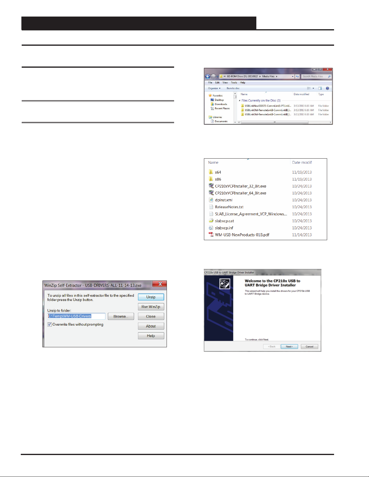
• USB drivers on CD-ROM (supplied and also
downloadable from orioncontrols.com)
• Microsoft Windows® 2000, Vista, 7, 8, or 10
(must be installed on the computer you are going to use)
• Prism 2 software, version 4.0.3 or later (can be
downloaded from orioncontrols.com)
Optional Items
• IP Module Kit that comes with Ethernet RJ-45
Crossover CAT 5, 10 ft. long cable for LAN, and Internet
remote communications
• MiniLink, MiniLink PD, or MinkLink PD 5
NOTE: AAON Controls Support cannot troubleshoot internal
PC and/or Windows®-based operating system prob-
lems.
General Information

QUICK START GUIDE
CommLink 5 Technical Guide
4
Quick Start Guide
Quick Start Guide
Follow the fi ve steps below to get your CommLink up and running in
no time.
NOTE: If you are using the CommLink 5 without utilizing
Prism 2, you need only perform Steps 1-3.
Step 1: Set your CommLink’s Loop switch to Multiple or Single.
See Figure 2 on page 6.
Step 2: Set your CommLink’s Baud rate switch to High or Low.
See Figure 3 on page 7.
Step 3: Wire your CommLink to the appropriate controller on your
system, and plug the CommLink into a power supply. See
Figure 1 on page 5.
WARNING: If you are replacing an earlier version of the Com-
mLink with a CommLink 5, be aware that the R(+) and T(-)
terminals on the communications terminal block are reversed
from all previous models of the CommLink 5. You must always
confi rm that the polarity is correct when wiring 24 VAC power
to the CommLink power terminal block or serious damage to
the product will result.
Step 4: Install the USB drivers located on the included CD-ROM.
See instructions on page 8. Then attach one end of the USB
cable to the back of your CommLink and the other end into
your computer’s USB port.
Step 5: Install Prism 2 software on your computer. See instructions
on pages 10 & 11.
NOTE: For remote communication, follow the instructions
included in your IP Module Technical Guide.
IMPORTANT NOTES:
First install the USB drivers, then follow the included
CommLink 5 connection and wiring instructions sheet
(Figure 1 on page 5) to connect and confi gure the
CommLink 5.
Familiarize yourself with all system components and
review all documentation. Pay special attention to
“Cautions,” “Notes,” and “Warnings” since these may
keep you from experiencing unnecessary problems.
If you encounter any problems, please refer to the
Troubleshooting section of this guide fi rst. If you
can’t resolve the problem, please call AAON Controls
Support at our toll free number—1-866-918-1100.

CommLink 5 Technical Guide
CONNECTIONS & WIRING
5
Connections & Wiring
Figure 1: CommLink 5 Connection & Wiring
24 VAC Power
If Desired A 24 VAC Transformer
Rated At 12 VA Minimum May Be
Used Instead Of The Supplied Power Pack.
Use 18 Gauge Minimum 2 Conductor Wire
Between The Transformer & CommLink 5
Terminals
(Not
Included)
120 to 24 VAC Power Pack
(Included) Connect To 120/1/60
Duplex Receptacle (By Others)
USB Cable (Included).
Connect This Cable To
Your Computer USB Port
For Direct Connection To
The CommLink 5. Also
Used For Advanced
Configuration of The
CommLink 5.
CommLink 5
Communications
Interface
CommLink 5 Connections & Wiring
NOTES:
1) Use 18 Gauge Minimum 2 Conductor Twisted Pair With Shield Cable Belden #82760 Or Equivalent (Not Included) To Connect
The CommLink 5 To A MiniLink or MiniLink PD.
2) For Direct Connection Via USB, Your Computer Must Have An Unused USB Port Available. Drivers For Your USB Port Are
Provided On A CD Supplied With The CommLink 5. Please Follow The Directions In The CommLink 5 USB Driver Installation
Section (Included) To Install And Configure The USB Drivers.
3) The CommLink 5 Cannot Communicate With The Control System Through Its Ethernet Port And USB Port At The Same Time.
4) All Wiring Must Conform To Applicable Federal, State & Local Electrical Wiring Codes.
18 Gauge 2 Conductor
With Shield (Not Included)
See Note 1
Connect To A
MiniLink PD, MiniLink
Or Other Controller As
Required By Your
Specific System
Wiring Instructions.
See Note 1
Serial #
COMPUTER
USB
10/100
ETHERNET
DIAG
485 LOOP POWER
ACT LNK
Optional Items
Not Required
For CommLink-Only
Installations.
When Using
A MiniLink,
Switch Should
Be Set To
Multiple.
HIGH
LOW
BAUD
R(+)
24V
GND
SHLD
T(-)
MULTIPLE
SINGLE
LOOP
WARNING! If You Are Using The IP
Module With Your CommLink, Do Not
Have Your Ethernet Connection And
USB Connection Connected At The
Same Time. This Could Cause
Unreliable Communications.
Optional - Prefabricated Ft. Long CAT5
Ethernet Cable (Included With Optional OE415-
02 IP Module Kit).
If A Longer
Ethernet Cable Is Required, You Will Need To
Obtain (From Others) And Install An Ethernet
Cable Of The Required Length For Your
Installation.
10
Connect To A 10/100 Base-T
Ethernet Router On Your LAN.
WARNING! If You Are Replacing An Earlier
Version Of The CommLink With A CommLink 5,
Be Aware That The Polarity Of The Terminal
Block Is Reversed On The CommLink 5 From
All Previous Models. You Must Always Confirm
That The Polarity Is Correct When Wiring 24 VAC
Power To The CommLink Power Terminal Block
Or Serious Damage To The Product Will Result.
NOTE: Please Note, The R(+) And T(-) Terminals
On The Communications Terminal Block Are
Reversed From All Previous Versions Of The
CommLink.

COMMUNICATION SETTINGS
CommLink 5 Technical Guide
6
Loop Communication Setting
Setting the CommLink 5 SettingCommunications
CommLink 5 Communications Setting
The Loop Switch Located On The Back Of The
CommLink 5 Housing Must Be Set Correctly For
Your Specific Application In Order For The
CommLink 5 To Function Properly.
The Switch Setting Should Be Set To
“Multiple” In The Following Situation:
You Have A Single CommLink With
MiniLink(s) or MiniLink PD(s) Installed On
Your System.
The CommLink
5 Is Factory Set For Multiple Loop Applications.
Loop
The Loop Switch Setting Should Be Set To
“Single” In The Following Situation:
You Have A Single CommLink Without Any
MiniLinks Or MiniLink PDs Installed On Your
System.
MULTIPLE
HIGH
SINGLE
LOW
BAUDLOOP
R (+)
24V
GND
SHLD
T(-)
SERIAL #
MULTIPLE
SINGLE
LOOP
Switch Set To Multiple
Loop Communications
MULTIPLE
SINGLE
LOOP
Switch Set To Single
Loop Communications
Back of CommLink 5
Figure 2: Setting Loop Communications

CommLink 5 Technical Guide
COMMUNICATION SETTINGS
7
Baud Rate Setting
Figure 3: Setting the Baud Rate

USB DRIVER INSTALLATION
CommLink 5 Technical Guide
8
USB Driver Installation
The internal USB communication port of the CommLink uses a
specialized driver that must be installed on your Windows PC before
communication to the device can be established.
NOTE: You may already have this driver installed on your PC if
you have used or are using a USB-Link 2.
1. Before you begin, you must determine if your computer
is running 32-bit or 64-bit Windows. Open the System
information by clicking the <Start> button, clicking
<Control Panel>, and clicking <System>. Under
System, you can view the system type. Based on what
type of system you have, you will choose 32_Bit.exe or
64_Bit.exe from the list of fi les shown in Step 10.
2. Insert the USB Drivers CD-ROM into your CD-ROM
drive or download the USB Drivers fi le from www.
orioncontrols.com/a/software/. If using the CD-ROM,
go to Step 7. If downloading the fi le, you will need to
scroll down the page until you fi nd “USB Drivers For
All Products” to download the driver fi les.
3. Right click on “Click Here.” Then click <Save Link
As> or <Save Target As> and select Desktop as the
destination.
4. Go to the “USB-DRIVERS-ALL.exe” fi le on your desk-
top. Double-click on this fi le and choose “Run” from the
options list. The following window will appear:
5. Select <Unzip> and the fi le will be unzipped to the
folder C:\Temp\WM-USB-Drivers folder by default.
6. Next, go to the C:\Temp\WM-USB-Drivers folder and
now go to Step 9.
7. Click your <Start> button and then click, <Computer>.
8. Double-click on your CD-ROM drive. Open the Media
Files Folder.
9. Double-click the folder “USBLink NewSS0073”.
10. The following list of fi les will display. Choose 32_Bit.
exe or 64_Bit.exe based on what type of system you
determined you have in Step 1.
11. In the window that pops up, shown below, click <Next>
and the installation program will walk you through the
rest of the steps.
12. When successful installation has occurred, connect the
USB cable between the PC and the USB-Link 2. The
PC will automatically recognize the device and a COM
port will be assigned. Follow the procedures on page 9 to
verify the Comm Port.
USB Driver Installation

CommLink 5 Technical Guide
USB DRIVER INSTALLATION
9
Finding What COM Port Number the
CommLink 5 is Using
1. Left-click on <start>, located on the bottom left or top
left of the Windows Tool Bar.
2. Select <Control Panel>.
3. Double-click the System Icon.
4. Click the <Hardware> tab.
5. Click the <Device Manager> button.
6. Click on the plus sign next to Ports to see all of the com-
mon ports.
7. Locate the USB Serial Port (COM#). The COM# in
parentheses is the port it is located on. Write this COM
port number down. You will need to know this when set-
ting up the Prism software.
8. If the COM port number is 10 or greater, go to “Chang-
ing the USB COM Port Number” in the Troubleshooting
section on page 15.
Finding the COM Port Number

PRISM 2 SETUP
CommLink 5 Technical Guide
10
8. In the Network Conguration selection box, select the
type of system conguration you are using. e only
options applicable to CommLink 5 are Multiple Loop
Conguration (Network) or Single Loop Conguration.
9. Click <Exit> to close out of the Job Sites Window.
10. Click the <OFFLINE> button to go
<ON LINE>.
11. From the <Communications> menu, select <Search
for Units>.
Prism 2 Setup Instructions
Prism 2 Setup
1. Open your Prism 2 soware.
2. Click the <Login> button and type in the level
3 User Name and password (default is “admin,
admin”). Click <Login>.
3. If Prism 2 is online, click the
<ON LINE> button to make it go
<OFFLINE>.
4. Click the <Job-Site> button to open the
Job-Sites Window.
5. Click on any empty location in the Job-Site Selection
Window and then type in a job name in the Selected
Location box and press <Enter>.
6. In the Serial Port eld, click on the pull down box and
select the COM Port number that the CommLink 5 is
using.
7. In the Type of CommLink selection box, select the radio
button next to CommLink 5.

CommLink 5 Technical Guide
PRISM 2 SETUP
11
Prism 2 Setup Instructions
12. e Search for Installed Units Window will pop up.
Click <Start Search> located in the upper le-hand
corner of the window to initiate an automatic detection
of all installed controllers on your system.
13. If everything is working correctly, Units Found on this
Loop should load into the pull down window located on
the right.
14. If Units Found on this Loop stays at zero, check the wir-
ing to the CommLink 5 and the AHU/RTU Controllers
and/or read through these directions again to make sure
all steps were followed.

TROUBLESHOOTING
CommLink 5 Technical Guide
12
CommLink 5 LED Descriptions
Figure 3: CommLink 5 LED Display
CommLink 5 LED Descriptions
USB LEDs
LOOP - Indicates communication activity on local controller
network. This LED fl ickers when data is exchanged with the
controller network.
TX-USB - Indicates transmitted data status of USB connection.
This LED only fl ashes when your CommLink 5 is connected
to a computer and data is sent to Prism from the CommLink 5
via USB.
RX-USB - Indicates received data status of USB connection.
This LED only fl ashes when your CommLink 5 is connected
to a computer and data is sent from Prism to the CommLink 5
via USB.
COMP- Indicates connection to your computer. This LED will
turn on solid once you plug the USB cable into your computer
as long as the connection is not lost.
NETWORK LEDs
ACT-LAN - Indicates activity on the local area network. This
LED fl ashes on when LAN is transmitting and receiving data
and is only operational with an Ethernet connection.
LNK-LAN - Indicates local area network is connected. This
LED is on when connected to LAN and is only operational
with an Ethernet connection.
WLAN - Indicates wireless connection to the local area network.
This LED fl ashes on when LAN is transmitting and receiving
data and is only operational with an Ethernet connection.

CommLink 5 Technical Guide
TROUBLESHOOTING
13
Connecting the Network
Figure 4: Example Network Diagram of a Firewall or Proxy Confi guration
Proxy and Firewall Compatibility
Proxy and Firewall configurations may become necessary
when the CommLink 5 is connected to a LAN/WAN that is pro-
tected by a commercially available Firewall, Proxy, or NAT enabled
router. Examples of these would include Cisco, NetGear, LinkSys,
or WatchGuard Technologies. Also, some ISPs provide IP Address
ranges that are already fi re-walled at the NOC or ISP Head-End.
Make sure that your IT Department or ISP can create a mapped TCP
port 39288 on your fi rewall/proxy to TCP port 39288 on the assigned
IP Address of the CommLink 5.
Only with proper confi guration of the Firewall/Proxy are connections
to the CommLink 5 from outside of the local area network going to
be possible. Check that the Firewall/Proxy TCP port 39288 is not
set to time out or reset after a specifi ed amount of time when there
is no traffi c from the remote PC.

TROUBLESHOOTING
CommLink 5 Technical Guide
14
Troubleshooting the USB Drivers
Troubleshooting Tips
Problems with Prism 2 Software
• Verify that the correct COM port, created by the USB
connection, is selected in the Job-Sites Window. Verify
COM port number by clicking <Control Panel>,
<System>, <Hardware>, <Device Managers>,
<Ports>.
• Verify that CommLink 5 is selected for Type of
CommLink in the Job-Sites Window.
• Verify that the correct CommLink mode is selected
under Network Confi guration in the Job-Sites Window.
Problems with USB Connection
• Verify that the TX-USB and RX-USB are blinking
when you perform a Search for Units or try to open a
status screen in Prism 2.
• If the USB LEDs fail to blink, disconnect and
reconnect the USB connection.
• If the problem persists, verify that the USB drivers
have been installed properly.
Problems Viewing Multiple Controllers on a Network
• Make sure that the CommLink’s communication
switch is set to Multiple.
• In Prism 2, make sure that Multiple Loop Confi guration is
selected for Network Confi guration in the Job-Sites
Window.
NOTE: AAON Controls Support cannot troubleshoot internal
PC and/or Windows-based operating system prob-
lems.
NOTE: AAON Controls Support cannot troubleshoot fi re-
walls, routers and/or problems on a customer’s internal
or external network. An IT professional may need to
be consulted.

CommLink 5 Technical Guide
TROUBLESHOOTING
15
Troubleshooting the COM Port Number
4. To assign a port number less than 10, click on
<Advanced>. The Advanced Settings Window
will appear.
5. In the COM Port Number drop box, select which COM
port you wish to use. Make sure you select a COM port
number that is not currently in use (you can see the ports
in use in the Device Manager Window). Select a port
number that is less than 10.
NOTE: Windows® will assign a port number to every device
that has ever been installed on your computer. So if
there are no available ports below 10, choose a port
number less than 10 for a device listed that you know
you are not currently using.
6. Once you select the correct COM port number, click
<OK> and close any windows opened in the process
of changing the port number. Make note of this number
because you will need it for your Prism 2 setup.
Changing the USB COM Port Number
When the CommLink 5 is fi rst plugged in, it will be assigned a
COM port number to be used for communicating with the Prism 2
software. If the port number is 10 or greater, it needs to be changed
to a value less than 10 to be recognized by Prism 2.
1. Click <start>, click <Control Panel>, click
<System>, click the <Hardware> tab, and then click
<Device Manager> to get to the Device
Manager Window.
2. Click on the plus sign next to Ports to see all of the COM
ports.
3. Right-click on “USB Serial Port (COM#)” and select
<Properties>. In the Properties Window, select the
<Port Settings> tab.

2425 South Yukon Ave • Tulsa, OK • 74107-2728
Ph: (918) 583-2266 • Fax: (918) 583-6094
AAON® Part No.: G015590, Rev. 01J
Printed in the USA • © June 2018 AAON • All Rights Reserved
Other manuals for CommLink 5
1
This manual suits for next models
1
Table of contents
Other AAON Recording Equipment manuals
Popular Recording Equipment manuals by other brands

Argiriadis Analogue Electronics
Argiriadis Analogue Electronics DU user guide

Peavey
Peavey KOSMOS V2 operating manual

Tascam
Tascam DR-08 release note

Brainworx
Brainworx Engl Savage 120 Plugin Manual

Bastl
Bastl Kastle ARP manual

Sonance
Sonance Industry Upgrade Automatic Secondary Source Selector... instruction manual