Brymen BM131 User manual

USER'S
MANUAL
BM131
BM132
BM135
LoggerClampTM Series

1
1) SAFETY
This manual contains information and warnings that must be followed for operating the
instrument safely and maintaining the instrument in a safe operating condition. If the
instrument is used in a manner not specified by the manufacturer, the protection provided by
the instrument may be impaired.
The meter meets the requirements for double insulation to IEC61 1 -2- 32(2 2),
EN61 1 -2- 32(2 2), UL61 1 B-2- 32(2 3):
Category III 6 Volts ac and dc.
PER IEC61010 VERV LTAGE INSTALLATI N CATEG RY
OVERVOLTAGE CATEGORY II
Equipment of OVERVOLTAGE CATEGORY II is energy-consuming equipment to be
supplied from the fixed installation.
Note – Examples include household, office, and laboratory appliances.
OVERVOLTAGE CATEGORY III
Equipment of OVERVOLTAGE CATEGORY III is equipment in fixed installations.
Note – Examples include switches in the fixed installation and some equipment for industrial
use with permanent connection to the fixed installation.
OVERVOLTAGE CATEGORY IV
Equipment of OVERVOLTAGE CATEGORY IV is for use at the origin of the installation.
Note – Examples include electricity meters and primary over-current protection equipment.
TERMS IN THIS MANUAL
WARNING identifies conditions and actions that could result in serious injury or even death
to the user.
CAUTION identifies conditions and actions that could cause damage or malfunction in the
instrument.

2
WARNING
To reduce the risk of fire or electric shock, do not expose this product to rain or moisture.
The meter is intended only for indoor use.
To avoid electrical shock hazard, observe the proper safety precautions when working with
voltages above 6 VDC or 3 VAC rms. These voltage levels pose a potential shock hazard
to the user.
Keep your hands/fingers behind the hand/finger barriers (of the meter and the test leads)
that indicate the limits of safe access of the hand-held part during measurement. Inspect test
leads, connectors, and probes for damaged insulation or exposed metal before using the
instrument. If any defects are found, replace them immediately.
This Clamp-on meter is designed to apply around or remove from uninsulated hazardous live
conductors. But still, individual protective equipment must be used if hazardous live parts in
the installation where measurement is to be carried out could be accessible.
CAUTION
Disconnect the test leads from the test points before changing meter functions.
INTERNATI NAL ELECTRICAL SYMB LS
!
!!
!
Caution ! Refer to the explanation in this Manual
Caution ! Risk of electric shock
Earth (Ground)
Double Insulation or Reinforced insulation
Fuse
AC--Alternating Current
DC--Direct Current
Application around and removal from hazardous live conductors is permitted
2) CENELEC Directives
The instruments conform to CENELEC Low-voltage directive 73/23/EEC and
Electromagnetic compatibility directive 89/336/EEC

3
3) PR DUCT DESCRIPTI N
This user's manual uses only representative model(s) for illustrations. Please refer
specification details for function availability to each model.
1) Transformer Clamp Jaws for AC
current magnetic field pick up
2) Jaw marking lines for ACA position
error indication
3) Hand/Finger Barrier to indicate the
limits of safe access to the jaws during
current measurements
4) Push-buttons for special functions &
features
5) Input Jack for all functions EXCEPT
non-invasive ACA current function
6) Common (Ground reference) Input
Jack for all functions EXCEPT
non-invasive ACA current function
7) Slide-switch Selector to turn the
power ON/OFF and Select a function
8) LCD display
9) Jaw trigger for opening the
transformer clamp jaws
1 ) Jaw center Indicators, at where
best ACA accuracy is specified

4
4) PERATI N
ACV & DCV functions
Set the slide-switch function-selector to the position. Default at last selected function.
Press SELECT button to toggle between ACV and DCV measurement functions. There is no
LCD annunciator for DC. LCD annunciator “ ” turns on to indicate AC is selected.
Line-level Frequency function
When voltage or current function is selected, press Hz button momentarily toggles to
Line-level Frequency function. Frequency trigger levels vary automatically with function
ranges.
THD%-R Total Harmonic Distortion - RMS function (model 135 only)
THD%-R = (Total Harmonics RMS / Total RMS) x 1 %
Total Harmonic Distortion - RMS (THD%-R) is the percentage ratio of the Total Harmonics
RMS value to the Total (Overall) RMS value of a voltage or current signal, and is given by
the above expression. An ideal sinusoidal waveform has a value of %. A badly distorted
sinusoidal waveform may have a much higher THD%-R value of approaching one hundred
(1 % is the maximum theoretical reading).

5
When voltage or current function is selected, press and hold THD%-R button for one
second or more toggles to Total Harmonic Distortion - RMS measurement function. The LCD
annunciator “%” turns on.
Note:
Specified accuracy at ACA fundamental > 5A; ACV fundamental > 5 V.
The meter displays “---.- %” when ACA fundamental < 1A; ACV fundamental <8.5V
ACA Current clamp-on function
Set the slide-switch function-selector to the position. Inputs are made through the clamp
jaws for non-invasive ACA current measurements.
CAUTION (Application and removal of the Clamp-on meter)
●For non-inva ive ACA current measurements, pre the jaw trigger and clamp the jaw
around only one ingle conductor of a circuit for load current mea urement. Make ure the
jaw are completely clo ed, or el e it will introduce mea urement error . Enclo ing more
than one conductor of a circuit will re ult in differential current (like identifying leakage
current) mea urement. Locate the conductor( ) at the Jaw center a much a po ible to
get the be t mea uring accuracy. For removal, pre the jaw trigger and remove the jaw
from the conductor( ).
●Adjacent current-carrying device uch a tran former , motor and conductor wire will
affect mea urement accuracy. Keep the jaw away from them a much a po ible to
minimize influence.

6
Temperature function
Set the slide-switch function-selector to the
o
C/
o
F position. Default at last selected function.
Press SELECT button to toggle between
o
C and
o
F measurement functions. Be sure to
insert the banana plug type-K temperature bead probe Bkp6 at correct polarities.
You can also use a plug adapter Bkb32 (Optional purchase) with banana pins to type-K
socket to adapt other type-K standard mini plug temperature probes.
Ω
ΩΩ
Ω/ functions
Set the slide-switch function-selector to the Ω
ΩΩ
Ω/ function position. Default at last selected
function. Press SELECT button to toggle between Ω
ΩΩ
Ω and measurement functions.
Hi-Lo Logging mode
Hi-Lo Logging is an innovation feature. It minimizes product cost for maximum monitoring
speed and period making field monitoring simpler and more affordable. Hi-Lo Logging
captures the most important surges (Hi) & sages (Lo) on intervals of every one-minute. That
is, the meter uses its highest update rate to compare and capture the highest and lowest
readings on every one-minute time interval. It can log up to 54 pairs of Hi/Lo readings and
thus 54 minutes of total logging period.

7
Press and hold the “Hi-Lo Log” button for one second or more to start “ ” a new Hi-Lo
Logging session. All previously logged data is erased! Annunciators “Max Min” flashes and
real-time measurement readings are being displayed. Press SELECT button momentarily
toggles to display logged data item number (number of one-minute time intervals). “ ”
displays in the secondary display.
Press the H LD button momentarily to pause. The LCD annunciator “ ” flashes. Press the
H LD button momentarily again to continue. Press and hold the “Hi-Lo Log” button for one
second or more again to stop “ ” and end the Hi-Lo Logging session. The meter can now
be switched off.

8
To recall, switch on the meter, then press the forward “ ” and backward “ ” arrow
buttons at the same time to recall “ ” the logged data. The meter displays in turn the
absolute maximum item number, absolute maximum reading, absolute minimum item
number, and then absolute minimum reading (of the whole logging period).
Press the forward “ ” (or backward “ ”) arrow button momentarily to read the next
logged data item. The meter displays in turn the one-minute item interval number “ ” (the
count of one-minute time intervals), Hi-reading “ ” (the highest reading), and then

9
Lo-reading “ ” (the lowest reading) of that one-minute item interval. Press-and-hold the
button can quickly scroll the logged items. The meter gives short beeps when the last (or the
first) item is reached.
Note:
1.
When the meter memory is full or the meter battery is low, the meter will stop (end) the
Hi-Lo logging session and go back to the normal measuring mode.
2.
The data is stored to the non-volatile memory shortly after every one-minute item interval
to maximize data safety. However, the end-of-data sign can be stored only after the Hi-Lo
logging session is ended with a session stop “ ”. Therefore, always stop “ ” the Hi-Lo
logging properly before sliding the slide-switch function-selector to the next function position.
3.
After the Hi-Lo logging session is ended, you can switch off the meter for transportation,
storage, or even battery changing. The logged data can also be downloaded to PC
computers through the optional purchase BR13X PC interface kit. Also see RS232C PC
computer interface capabilities section.
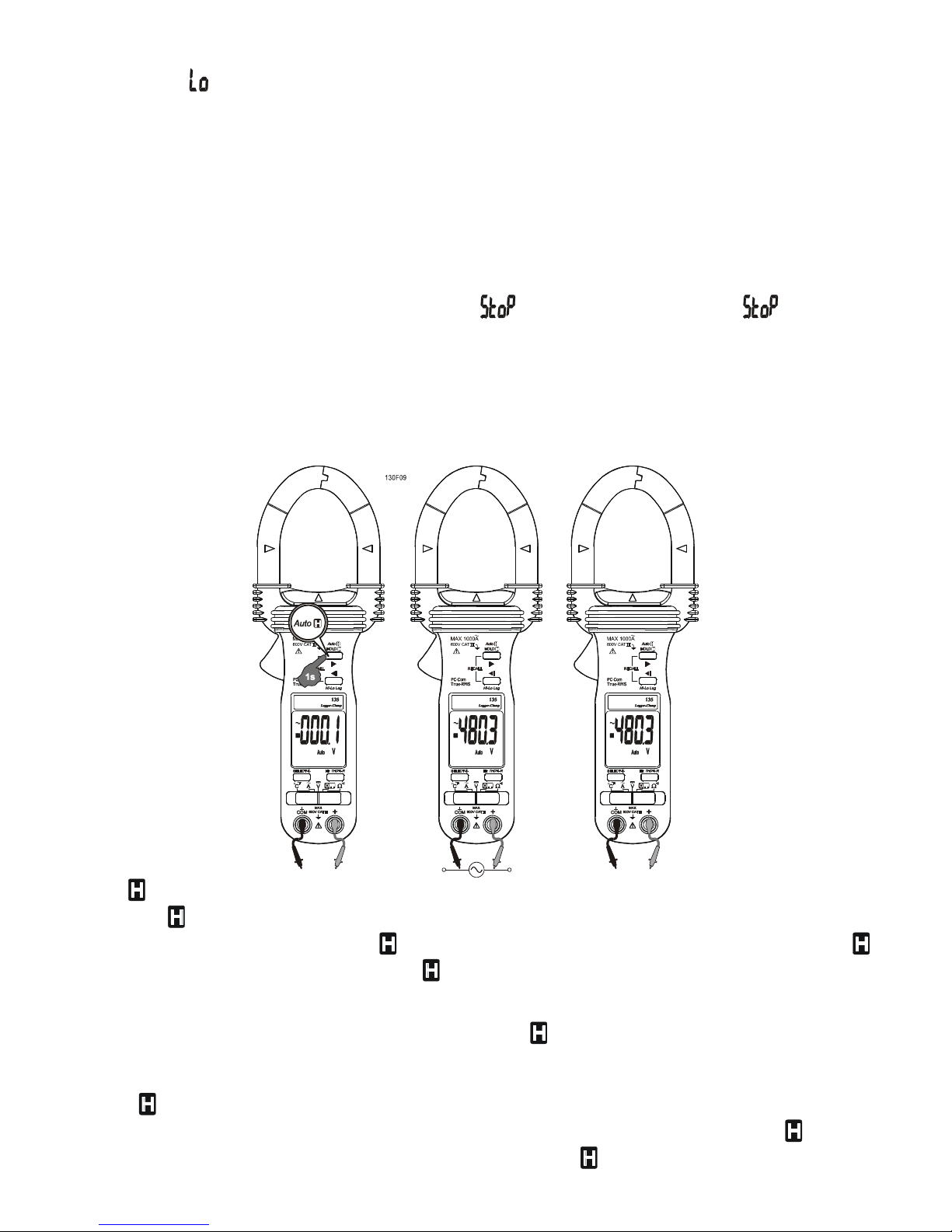
Auto feature
The Auto (Automatic-Hold) feature automatically captures and displays significant stable
readings. Press and hold the Auto button for one second or more to toggle to the Auto
mode. The LCD annunciators “Auto” & “ ” turn on.
WARNING
To avoid electric shock hazard, do not use the Auto (Automatic-Hold) mode to determine
if a circuit is live. Unstable readings will not be captured and displayed.
H LD feature
The Hold feature freezes the display for later viewing. Press the H LD button
momentarily to toggle to the Hold mode. The annunciator “ ” turns on.

10
Display Backlight (model 132 & 135 only)
Press the SELECT button for 1 second or more to toggle the display backlight on and off.
Auto Power ff (AP )
The meter turns off after approximately 16 minutes of neither switch nor button activity. To
wake up the meter from APO, slide the function-selector to other positions and back on
again. Always turn the function-selector to OFF when the meter is not in use.
Disabling Auto-Power- ff (AP )
Press-and-hold the H LD button while sliding the function-selector to a (designated)
function-selector position. This disables the Auto-Power-Off feature of the functions on that
particular function-selector position. The LCD displays “ ” & “ ” to confirm activation
right after the H LD button is released. Slide the function- elector to any other po ition
afterward re ume Auto-Power-Off feature.
RS232C PC computer interface capabilities
The instrument equips with an optical isolated data output port at the bottom case near the
battery compartment. Optional purchase PC interface kit BR13X (including BA-1XX Optical
Adapter Back, BC-1 R Cable & Bs13x Software CD) is required to connect the meter to PC
computer thru RS232C protocol. The RS232C Data Recording System software Bs13x
equips with a digital meter, an analog meter, a comparator meter, and a Data Graphical
recorder. Refer to the README file that comes with the interface kit for further details.
Note: Unlike 15 series, data output feature of 13 series is activated automatically by
Bs13x software when the meter is correctly connected and linked to the computer software.
No manual activation is required. APO is also disabled during data output.
5) MAINTENANCE
WARNING
To avoid electrical shock, disconnect the meter from any circuit, remove the test leads from
the input jacks and turn OFF the meter before opening the case. Do not operate with open
case.
Trouble Shooting
If the instrument fails to operate, check batteries and test leads etc., and replace as
necessary. Double check operating procedure as described in this user’s manual
If the instrument voltage-resistance input terminal has subjected to high voltage transient
(caused by lightning or switching surge to the system) by accident or abnormal conditions of
operation, the series fusible resistors will be blown off (become high impedance) like fuses to
protect the user and the instrument. Most measuring functions through this terminal will then
be open circuit. The series fusible resistors and the spark gaps should then be replaced by
qualified technician. Refer to the LIMITED WARRANTY section for obtaining warranty or
repairing service.

11
Cleaning and Storage
Periodically wipe the case with a damp cloth and mild detergent; do not use abrasives or
solvents. If the meter is not to be used for periods of longer than 6 days, remove the
batteries and store them separately
Battery replacement
The meter uses standard 1.5V AAA Size (NEDA 24A or IEC LR 3) battery X 2
Loosen the 2 captive screws from the battery cover case. Lift the battery cover case.
Replace the batteries. Replace battery cover case. Re-fasten the screws.
6) Specifications
General Specifications
Display :
Voltage functions: 6 counts LCD display
Ohm & Hz functions: 9999 counts LCD display
ACA clamp-on function: 4 counts LCD display
Update Rate :
Voltage, ACA clamp-on, Ohm & Temperature functions: 4 per second nominal
Hz function: 2 per second nominal
Polarity : Automatic
Low Battery : Below approx. 2.4V
perating Temperature :
o
C to 4
o
C

12
Relative Humidity : Maximum relative humidity 8 % for temperature up to 31
o
C
decreasing linearly to 5 % relative humidity at 4
o
C
Altitude : Operating below 2 m
Storage Temperature : -2
o
C to 6
o
C, < 8 % R.H. (with battery removed)
Temperature Coefficient : nominal .15 x (specified accuracy)/
o
C @(
o
C -18
o
C or 28
o
C
-4
o
C), or otherwise specified
Sensing : Average sensing for model 131; True RMS sensing for model 132 & 135
Safety : Meets IEC61 1 -2- 32(2 2), EN61 1 -2- 32(2 2), UL61 1 B-2- 32(2 3)
Measurement Category III 6 Volts ac & dc
Transient protection : 6.5kV (1.2/5 µs surge) for all models
Pollution degree : 2
E.M.C. : Meets EN61326(1997, 1998/A1), EN61 -4-2(1995), and EN61 -4-3(1996)
In an RF field of 3V/m:
Total Accuracy = Specified Accuracy + 45 digits
Performance above 3V/m is not specified
verload Protections :
ACA Clamp-on jaws : AC 1 A rms continuous
+ & COM terminals (all functions) : 6 VDC/VAC rms
Power Supply : standard 1.5V AAA Size (NEDA 24A or IEC LR 3) battery X 2
Power Consumption :
Voltage & ACA functions: 3.5mA typical
Ohm & Temperature functions: 4mA typical
AP Timing : Idle for 16 minutes
AP Consumption : 1 µA typical
Dimension : L224mm X W78mm X H4 mm
Weight : 224 gm approx
Jaw opening & Conductor diameter : 45mm max
Special features : THD%-R Total harmonic distortion-RMS (model 135 only); Display
Backlight (model 132 & 135 only); Auto-Hold; Display Hold; On screen stand-alone Hi-Lo
logging (54 minutes) at sampling speed of faster than:
2 per second for Voltage & ACA functions
4 per second for Ohm & Temperature functions
2 per second for Hz function
Accessories : Test leads (pair), batteries installed, user's manual, BKP6 banana plug
type-K thermocouple & soft carrying pouch
ptional accessories : BR13X PC interface kit (including BA-1XX optical adapter back,
BC-1 R cable & Bs13x software CD), BKB32 banana plug to type-K socket plug adaptor
Electrical Specifications
Accuracy is ±(% reading digits + number of digits) or otherwise specified, at 23
o
C ±5
o
C &
less than 75% R.H.

13
True RMS Models 132 & 135 ACV & ACA clamp-on accuracies are specified from 5% to
1 % of range or otherwise specified. Maximum Crest Factor are as specified below, and
with frequency spectrums, besides fundamentals, fall within the meter specified AC
bandwidth for non-sinusoidal waveforms. Fundamentals are specified at 5 Hz and 6 Hz.
AC Voltage
RANGE Accuracy
50Hz / 60Hz
6 . V 1. % + 5d
45Hz ~ 500Hz
6 . V 1.5% + 5d
500Hz ~ 3.1kHz (model 132 & 135 only)
6 . V 2.5% + 5d
CMRR : >6 dB @ DC to 6 Hz, Rs=1kΩ
Input Impedance: 2MΩ, 3 pF nominal
True RMS models Crest Factor:
< 2.3 : 1 at full scale & < 4.6 : 1 at half scale
DC Voltage
RANGE Accuracy
6 . V .5% + 5d
NMRR : >5 dB @ 5 /6 Hz
CMRR : >12 dB @ DC, 5 /6 Hz, Rs=1kΩ
Input Impedance: 2MΩ, 3 pF nominal
THD%-R
1)
(model 135 only)
RANGE Harmonic order Accuracy
2)
Fundamental 1.5% of Reading + 6d
2nd ~ 3rd 5. % of Reading + 6d
4th ~ 1 th 2.5% of Reading + 6d
. % ~99.9%
11th ~ 51st 2. % of Reading + 6d
1)
THD-R is defined as: (Total Harmonic RMS / Total RMS) x 1 %
2)
Specified accuracy @ ACA fundamental > 1 A ; ACV fundamental > 1 V
3)
Add 6d to specified accuracy @ THD-R below 1 %
hms
RANGE Accuracy
999.9Ω 1. % + 6d
Open Circuit Voltage : .4VDC typical

14
Audible Continuity Tester
Audible threshold: between 1 Ω and 3 Ω.
Response time: 25 µs
Frequency
Range Accuracy
5. Hz ~ 5 . Hz .5%+4d
Sensitivity (Sine RMS)
4 A range: > 4A
4 A range: > 4 A
1 A range: > 4 A
6 V range: > 3 V
Temperature
RANGE Accuracy
1)
-5
o
C ~ 3
o
C 2. % + 3
o
C
-58
o
F ~ 572
o
F 2. % + 6
o
F
1)
Add 3
o
C (or 6
o
F) to specified accuracy @ -2
o
C ~ -5
o
C (or @ -4
o
F ~ -58
o
F)
Type-K thermocouple range & accuracy not included
ACA Current (Clamp-on)
RANGE Accuracy
1) 2) 3)
50Hz / 60Hz
4 . A, 4 . A, 1 A 1. % + 5d
45Hz ~500Hz
4 . A, 4 . A 2. % + 5d
1 A 2.5% + 5d
500Hz ~ 3.1kHz (model 132 & 135 only)
4 . A, 4 . A 2.5% + 5d
1 A 3. % + 5d
True RMS models Crest Factor:
< 2.5 : 1 at full scale & < 5. : 1 at half scale for 4 . A & 4 . A ranges
< 1.4 : 1 at full scale & < 2.8 : 1 at half scale for 1 A range
1)
Add 8d to specified accuracy while reading is below 1 % of range
2)
Induced error from adjacent current-carrying conductor: < . 6A/A
3)
Specified accuracy is for measurements made at the jaw center. When the conductor is not
positioned at the jaw center, position errors introduced are:
Add 1% to specified accuracy for measurements made WITHIN jaw marking lines (away
from jaws opening)
Add 4% to specified accuracy for measurements made BEYOND jaw marking lines (toward

15
jaws opening)

LIMITED WARRANTY
BRYMEN warrants to the original product purchaser that each product it manufactures will
be free from defects in material and workmanship under normal use and service within a
period of one year from the date of purchase. BRYMEN's warranty does not apply to
accessories, fuses, fusible resistors, spark gaps, batteries or any product which, in
BRYMEN's opinion, has been misused, altered, neglected, or damaged by accident or
abnormal conditions of operation or handling.
To obtain warranty service, contact your nearest BRYMEN authorized agent or send the
product, with proof of purchase and description of the difficulty, postage and insurance
prepaid, to BRYMEN TECHNOLOGY CORPORATION. BRYMEN assumes no risk for
damage in transit. BRYMEN will, at its option, repair or replace the defective product free
of charge. However, if BRYMEN determines that the failure was caused by misused,
altered, neglected, or damaged by accident or abnormal conditions of operation or handling,
you will be billed for the repair.
THIS WARRANTY IS EXCLUSIVE AND IS IN LIEU OF ALL OTHER WARRANTIES,
EXPRESSED OR IMPLIED, INCLUDING BUT NOT LIMITED TO ANY IMPLIED
WARRANTY OR MERCHANTABILITY OR FITNESS FOR A PARTICULAR PURPOSE OR
USE. BRYMEN WILL NOT BE LIABLE FOR ANY SPECIAL, INDIRECT, INCIDENTAL OR
CONSEQUENTIAL DAMAGES.
BRYMEN TECHN L GY C RP RATI N
TEL:+886 2 2226 3396
FAX:+886 2 2225 0025
http://www.brymen.com
PRINTED ON RECYCLABLE PAPER, PLEASE RECYCLE
COPYRIGHT © MMV Btc, ALL RIGHTS RESERVED
P/N:7M1C- 581-A PRINTED IN TAIWAN
This manual suits for next models
2
Table of contents
Other Brymen Measuring Instrument manuals