BSA Winged Wheel W1 User manual

"STRUCTIOH
MÄË:NUËr "f7
EZIFE
"á¢d;máft
Modél "

Instruction Manual
for
ȧH
WNGE:D WHE:E:L
Model Wl
B.s.A. aycLËs l.TD.,
Waverley Works' BIRMINGIIAM, lO
Director¢ :
SIR BERN^RD DocKER. K.J3.E., (C/io"mw).
J 1_EEx. c.B.E. J. A. T. DlcKNsoN, o.Bri. S. F. D[c".
T. P. WHITTINGTON_
r¢léPAone_. Bimingham Victoria 37l l (6 hnes).
rehzgróims a"út C4ójes.. '( Selcyc.'' Bimringham.
B.S.±:_f%.:±_?__L_P.:r_spreJ?Í._ _+gm lo ftti:' thc des.gns o' any
const"ti"al detail.s..of !h¢jr-n.a"fa£iures-a;-á-n®;-ti-;c
w4lhoú giv®ng notüe.
WW+8oi+-Io-Io-Io Printed in F,nglaod jiéüj"t! Jam ]95s
cop!right B.s.A. co. Ltd.

TEcHNlaAL I)ATA.
CONTENTS.
Brake
Carburetter ...
Clutch
Controls
Pag?s
ll, 22
3l
"..9, 10, 2[
7, 9
Cylinder Head and Barrel Removal 28
Driving
Decarbonismg
Electrical Equipment
Exhaust Port
Fitting Unit
Fuel (Petroil)
Hub Bcarings
lgnition Timing
Lighting
Lubrication ...
Magneto
Maintenaince and Adjustment
Petrol Tank Fitting
Piston Rmgs Gap...
Running-in ...
Silencer Cleaning ...
Sparkmg Plug
Starting
Technical Data
Transmission Oil
l4
23
35
2.5
4
12
:3
3
13
35
18
7
3
15
30
14
3
]3
Petrol tank capacity (approx. ) Ha.lf ga.llon
"Petroi1" mixture Ilalf gallon petrol and two
measures oil (20 to 1).
Gearcase capa,city One-eighth pint (l± measures)
Bore 36mm.
Stroke 34mm.
Capacity (swept volume) 35c c.
Piston ring ga.p .006/.O l Oin.
Ignition timin# Piston distance before top dead
centre (t.d c.) with points Just opening 5/32in.
Plug point gap O20in. to O22in. (.Slmm.to.56mm.)
Contact breaker point setting .O l sin.
Gea.r ratio l8.7 to l
Reaï tyre 26in. x l iin. (Dunlop Carrier)
Reartyrepressure (lb) 40 43 46 49 52 S5
Rider'sweight(stones) 7 8 9 10 ll l2
Carburetter type Amal 335/ l
Standard jet 27
Jet needle position Centre notch
Dry weight of eligine and wheel 26±lb.
Dry weíght of petrol tank/carrier 3tlb.
Correct bulbs to use r F'ront lamp 6v. 6w
when lamps are fitted <i Rear hmp 6v.45A or.5A

Í
HOW TO FIT A B.S.A. WINGBD WIïEEl,
TO YOUR BICYCLE.
It is quite likely tha,t the dea,ler from whom you
purcha.se the B.S.A. WINGED WHEEL will do
this work for you. but some users may prefG.r to fit
the unit themselves, in whicli case tlie following
notes will be of some help.
This work is carried out in three separate stages
which are as follows :-
Fitting the actua,l unit to the frame.
Installirig the petrol tank.
Fixing the three control levers to the handle-
bars.
Since the machine `rill be ridden at much higher
speeds than when used as a normal bicycle, it will
be subJected to considerably greater road shocks.
It is strongly a,dvised that the a,djustment of the
head and front wheel bearings are ca,refully checked,
and that such a.tta,chments as mudguards are ma.de
secuie. The use ol spring washers is advised.
Fittíng the Unit to the frame.
The overallwidth of the l3.S.A. WINGED WHEEL
is 4-ll/l6" between the face ol the cone locking
washel a,nd the spindle locknut. This means that
the unit will fit directlv between the fork ends of a
sta,ndard bicycle. Thc.re may be a slight variation
as between one bicycle and another, a.mounting to
about one-eighth inch more or less than this figure,
but the fork elids will easily sPyj??g to this extent.
If tlio width between the fork ends is appreciably
less than 4-"/I6J", it will not be possib]e to fit the
B.S.A. WINGI:D WIll.-J.:I, "nveniently, but if,
Í)n the other h,,irid. the wi(lth Li somewhat grf.ater
r,ha,n ths dinielisi.)n, ,bnc th. distam.e mav be taken
4
-.~ (,'.l± í_~ - ,_
(
up with suitable packing washers, always provided
tha,t there is eliough length of spindle left at each
side to allow for the proper fitting o£ the chain tei]-
sioners, mudguard stays and wheel spindle nuts.
On ma.chines fitted with chain covers or oil baths
it may be necessary to' fit a washer on the spindle
and a number 4 Sprocket to ensure that the brake
drum dm not rub.
Fig. l. Fitting between fork ends.
Assuming tha.t the width between the íork ends
is suita,ble, it is only necessary to slacken the wheel
spindle nuts right ba,ck, or better still remove them
altogether. and to slide the wheel iI]to position in
the same manner as that adopted for the fitting oí
ali ordina.ry bicycle rea,r wheel. Next fit the chain
a.djusters, the mudguard sta,ys, and the wheel
spindle nuts. In the case of a sports type frame,
5

(
the fork ends wi]l be oí the drop-out pattem and
no chain adjusters are íitted. Screw the cliain
adjusters in or out until the correct tensioI] is
given to the pedalling chain, and then lightly
tighten the wheel spindle nuts. When settiI]g íor
chaii] tension, see that the wheel is also in correct
tra.ck alignment.
Fig. 2. Tank filler cap an(1 mea.sure for oil.
Next turn your attention to the torque rea.ction
clip.4, Fig. 7, which fits over the chainstay Alter-
native clips for round and Dshape stays are pro-
vided with each engine. When tightening the clip
bolt, it is essential that no side strain is pla.ced on
the unit by íorcing the torque arm inwards oT. out-
wards to conta.ct the fa,ce of the clip. If necessary,
set the arm slight]y, adjusting the offset to suit
the individual conditions, or if the displacement is
very small use washers as a paclring between clip
and arm. Tighten the clip bolt securely. It only
remains for the wheel spindle nuts to be given a
6
(
final tum of the spamer. and the unit rill be
correctly fitted in position.
Petrol Tank.
This is bui]t into a separate carrier which is
supI)orted on the backstays by two clips whcse
method of assembly is clearly scen at Á, F]'L,. 2.
apd by a special attachment unit which goes above
the backstay bridge. To attach this it is only
necessary to place the ba.r Í? against the rear of
the trin backstay tubes, fit the cliI) C in the po§ition
shown and insert and tighten up the centre locking
pin D. In order to place bar B correctly against
the backstay tubes it may be necessary to slacken
the nuts E slightly, tightening them afterwards.
The operation of fitting the tank l's completed
when the petrol pipe between the tap and the
carburetter is attached.
See that petro] tank is level-or with a slight
downward tllt at rear-when fitted. Otherwíse a
quantity of luel wi11 remain in the íorward end
and provent a full half gal]on being accommodated
when refilling.
On bicycles having a bent top rail a special
attachment íor the tank is necessary to ensure
level fitting; this can be obtained through your
local dealer.
When fimng wíth fuel for the first time see that
therc. is no airlock in the pipe.
Handlebar Controls.
When the B.S.A. WINGEI) WIIEEL is delivered
the three control cables are alreacly attached to the
unít, aI`d it is therefore only neccssary to lead the
cables along the fraime tubes and fix them wíth
the rubber clips provided.
7

Throttle.
The combined throttlo and strangler control ,Í,
Fig. 3, is mounted above the right handlebar, aind
attached by a cliI) in the normal mamer as shown.
"-ëii-
Fig. 3. Ha.ndlebal controls
Brake.
1,`or convenieuce in driving the bral" c()ntro]
should be mounted oli the right handleba,r, a.nd
since on the majority of pedal bicycles the rea,r
bra,ke control is riorma,lly oii the left, and tho froqt
. brake on the right, this will involve movírig the
front control lever to the left bar. Fig. 3 shows
this arrangement with the B.S.A. WINGED
WHEEL brake control at B.
8
(
Clutch.
The clutch controI C, which also incoiporates a
ratchet retailiing device, is mounted, in a similar
manner to the brake lever, on the left handlebar.
Adlustments.
After the three control levers haJ,e been mounted
on the handleba.rs " described a,bove. it will bo
necessary in the ca.se of the clutch and t)rake levers
to adjust them properly Full instruction§ _'or this
are gïven on pag® 2l and 22.
THE CONTROLS.
When fitting the controls, avoid sliarp bends in
the cables. It is advisable to fit the cable cupg at
the top and bottom of the £ront down tube and on
tho chainstay.
Throttle.
The carburetter throttle, which controls the
amount of gas entering the cylinder, and therefore
the amount of power developed by the engúe and
the speed of the cycle, is operated through a Bowden
cable by lever ,4, Fig. 3, on the right handlebar.
The throttle is opened when the lever is movod h
a clockwise direction, as indicited by the anow
in the illustration.
The operation of the carburetter stramgler íol cold
starting (see pages lO, l4 and 3l) is also períomod
by the throttle lever when it is moved beyond tho
position at whích full throttle i§ obtaiined. Fun
instructíons with regard to tbis are given mder
the heading of "Stairting" on page l4.
9

The twist grip throttle control which may be
fitted, opera,tes in aii anti-clockwise direction to
open throttle. To start from cold the trigger (,-
Fig. 3, is pushed downward giving the necessary
additional movement to the twist grip to bring the
carburetter st,rangler into operation. The trigger
returns to the normal position as the twist grip is
closed, and thereafter restricts movement to the
normal operationa,l range.
Note that the adjuster at the carburetter end of
the throttle cable ís for adjustment of cable length
only, and should not under anv circumstances, be
used to give a "tick over" with the throttle closed,
as this will cause the strangler to come ínto opera-
tïon at full throttle, causing partial choking aníï
increased petrol consumption.
Adjustment should be set so that the strangler
flap sta,rts to operate immediately after the lever
or twist grip is taken past the full throttle stop
when the trigger is lifted.
Clutch.
The clutch control lever is mounted on the left
handlebar as shown at C, Fig. 3, a,rid it operates
Fig. 4. Clutch a.djustment.
lU
the clutch withdrawal mechanism through a Bowden
cable, the actuating lever at the other end of the
cable being seeri in Fig. 4
When the clutch lever is pulle`1 up as fara,s it will
go tc)wards the ha,ridlebar. the drive is discontiected
betweea the engine and the rea,r wheel. The lever ís
locked in this p,sition by a, ratchet E, Fig. 3. To
eiigage the clutch it is only r"cessa,ry to disengage
the ratchet by pressing it inwards, and then relea,se
the clutcli lever. This must be done gradua.uy in
order to ensure shooth engragement.
Brake.
The rear brake control lever is mounted under
the right handlebar and opera,tes through a Bowden
cable, the a.ctuating lever at the other eI]d being
seen in Fig. 5. In common with all halidlebar
controlled brakes the large extemal expanding
Fig. 5. Brake cable a,djustment.
m

brake in the B.S.A. WINGED WHEEL is applíed
: when the lever is pulled towards the handlebar and
relea,sed when the lever is relased.
PREPARING FOR THE ROAD.
Petroíl.
The B.S.A. WINGED WHEEL engine operates
on tho PETROIL system, which means that engino
oil is dissolved in the petiol and automaticauy
provjdes correct lubrication without any íurther
responsjbility on the part of the rider, beyond that
of supp]ying a míxture of a suitable strength when-
ever the petrol ta,rik is refilled.
Instructions íor the correct proportions of petrol
alid oil are marked on the tank filler cap (see Fig2),
whicha.lsoincorporates a mea§ure, a,nd itwi]] benoted
that two fills of oil £rom this measure are correct
for half a gallon of petrol, the resultant quantíty
of PETROIL mixtuie being sufficient to fi]l the ta,nk.
The mixing of the petrol and oil should preíerably
be carried out in a separate container beíore behg
put in the tank, to ensure that the oil is thoroughly
dissolvod, but íf it is not practicable to do thís, the
oil should be poured into the tank first, followed by
the petrol, and the bicycle should be vigorou§1y
shaken sidewa.ys a few times in order to make suro
that the two liquids are properly mixed.
"PORTANT.- Do not lay machine on its síde íor
the purposes of adjustment or tyTe repair without
first removing or drainíng carburetter. The
petrol-oil mixture is liaible to draili out of the car-
buretter into the brake drum where the oil content
wnl reduce braking efficiency.
l2
Shell
TABLE I.
RECOMMENDED OILS.
(Summer and Winter)
Brand
Grrie
MobiloiI BB
Essolube Ebso 40
Castrol XXI.
B.P. Energol SAE 4O
XlOO40
*We also approve theuse®í ±he petrol/oíl mixture
No. l aa supp1íed by the Shell-Mex and B.P. Two-
Stroke Petroíl Servïce.
Oll íor Transmisslon.
There is a separato oil supply for the transnrission
gear, and beíore starting íor tho first time thͧ must
be filled to the corr«t level. Filler phg Á, Fíg. 6,
i§ províded for thí9 purpose.
The correct quantity of oil is } pút (approx. l!
measures), and the recommoI]ded grades aro tho
same a.s thme givon ín Table l above.
Fig. 6. Gearcase filler cap.
l3

Starting.
First, turn on the petrol tap by pulling the knob
out. Then if the engine is cold (j.e. if it has not
nin for a few hours, and the temperature has there-
fore íallen to atmospheric level), it will proba,bly be
necessary to close the strangler in order to ensure
an easy start. To do this, press the triggor D,
Fig. 3, inwards irith the thumb and, holding it
thus, open throttle lever 4, by moving it in a.
clockwise direction to its fullest extelit. The
thumb may then be taken írom the trigger,
which will remain out of enga,gement until it is
allowed to ratchet back.
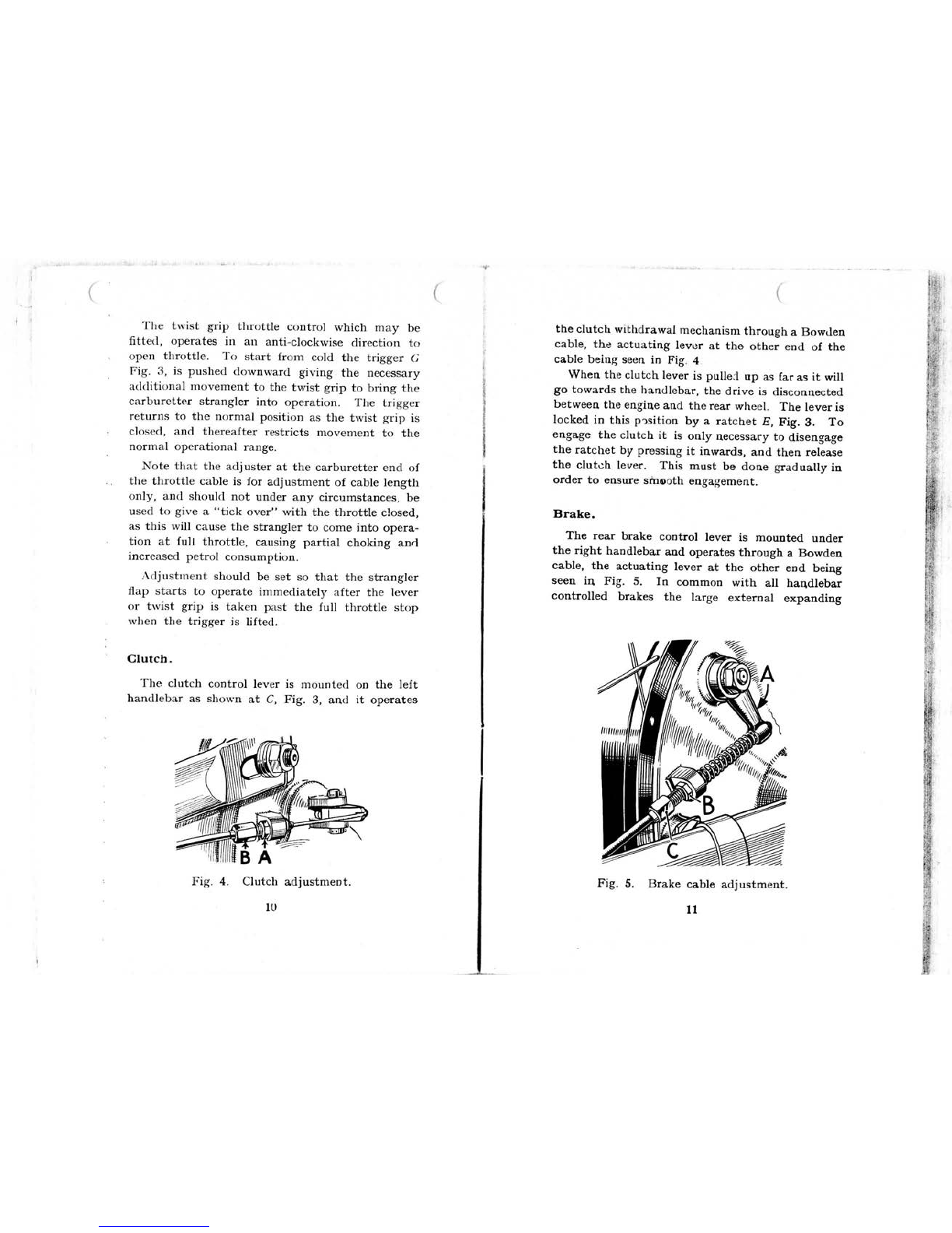
Release thc clutch by pulling up lever C, to
its íullest extent, in which position tho clutch
`rill be held out by the ratchet E`. Theli mount
the bicycle and pedal off in the normal manner.
When a suitabk. speed has been obtained, depress
the ratchet and gladuaily release the clutch lever.
This will couple the engine to the rear wheel and
cause the íormer to rotate, whereupon it should
immediately commence firing.
As sooii as the engine is running smoothly, which
should not ta.ke more than a secorid or so, ease the
throttle lever back slightly in order to release the
stra.ngler. The machine can then be ridden nor-
ma]ly a.s described iI] the next sectíon.
Drlving.
The speed of the engine and therefore of the
bicycle is controlled by the throttle lever and within
the limits of the performance of the B.S.A. Winged
Wheel it gives a uniíorm range of speed from a
walking pace with the throttle neaïly closed ríght
up to the maximum speed on the level amounting
to about 25 m.p.h. with corresponding lower speeds
on hills.
l4
Pedal assista.nce should never be riecessary on
the level except perhaps for starting, and aga.inst
a strong head wind, but it is expected that a smau
amount oí pedalling `rill be necessary occasionauy
on gra,dients, and the rider will rapidly learI} by
experience how best to a.ssist the engirie in this
resI)ex)t. The engine should never be auowed to
labour, and it will be íound that on quite severe
gra,dients the pedalling does not call for much
physical effort be¬ause it is only a matter of supply-
ing a little extra power above and beyond tha,t of
which the engine is ca,pable.
Any temptation to "drive on the brake," should
t)e avoided as it is obviously futile to have the
engine generating on one hand, amd íor that power
to be a.bsorbed on the other. When the occasion
arises for stopping or s]owing down, the throttle
should be closed and the clutch must be disengaged
before the brake is applied in order to avoid snatch
in the transmission.
Runnlng-in.
Running-in is really the most important period
in the liíe of the engine, and the handling you give
it during the early part of its liíe will determine,
what sort of service it is going to gíve you later.
If you try to put it through its pa,ces too soon
you will run the risk of seizure and other troubles
which may ha.ve a lasting eÍÏect on the engine, and,
iI` any case, until it is rea.1ly ruri-in it wil] not be
at its best. So give your engine a chance to settle
down during the first 250 miles of its life.
Avoid sudden and sharp acceleration. Do not
force it up hills, when a small amount of pedalling
would ea.se the load.
l5

Í
èarry out the periodical mahtelianco details
daicribed later irith faithíul regularity.
ÄÍter the first l50 milö, release the drain scr®w
J4, Fig. & two turu, whicl) will allow ainy oil which
may have accumulated to draín out. Wqi +he
Fig. 7. Süe elevation of unit.
pgtrou lubrication system employed there is never
a considerable quantity oí 1iquid oil in the crank-
case, but wha,tever oil there is should be drained
away, and this is preíerably done while tho mgine
is wam immediately after ai run, aB the oil wrill flow
l6
(
more íreely a.nd carry with it any íoreign matter
which lnay have fotind its way into the crankcas®
duritig the running-h proc®s.
Make certain on roplacing the screw that it is
made quite tignt iI) order tp prevent loss of crank.
case compi.ession.
Fig. 8. Front elevation of urit.
Note. This drain screw on]y concems tbe crank-
case, and not the ge":case, whích cam only be
emptied via the plug Á, Eg. 6.
l7

(
MAINTENANCE ANI) ADJUSTMENT.
General.
Th. amount of maíQtenance and adjustment of
¢ho WINGEI) WHEEL ha® been reduced to a
mhi"m, but tb fouowing points may requiro
attentíon írom time to tho amd they should
certa.inly be checked periodicany, say onco a weok
and rectify if nocegsa']r h the manner described
below.
Hub bearing adJustment.
There aro two sets o£ beaffings in tho hb, theso
beiQg the cup and cono ban bearhg§ Íor tho sphdb
itself. and a sqparato cup and cone ball boaüg ror
the pedalling gear sprocket and fi.ee wheel. The§o
are an adjusted simultaneously when tho fouowiag
procedure is adopted.
First suppoft tho bícycle, eíther on a box mder
the bottom bracket or by a rope slmg mder tho
saddle in such a way that the reaJ whoel is cleair
oí the ground. Next slacken oír the oÍÏsido wheeI
spindle nut ,4, Fig. 9. and the"elea£e tho lockíQg
waúher.B by 8üding it sideways aloag tho spíndlo
groov®, sufficient to free the spamer flats on ad-
justing cone. Disengage the clutch by means of tho
lever on the hdlebar aind lock it in tho fiee position
by allowiag the ratchet ,E, Fig. 8, to engago. "n
wíth a spanner on tho adjusting cone, eitha screw
this in or out as necessary mtn the wheel can still
be revolved freely, although but a s]ight íurther
turn oí the adjusting cone h a clockwíse directioli
results in an appreciable tighteriDg of tho whool.
18

When this point hs been reached it means that all
the play in the bearings has been taken up, and
a,ny further tightening o£ the cone will put ai` actual
thrust on the steel balls. This must be avoided at
all costs, and the correct thing to do when the play
has all been taken up as just described, is to un-
screw the cone a. small fraction of a tum. When
the wheel is now grasped by the tyTe and moved
sideways it should be possible to feel a small amoulit
oí play, or shake, which should not exceed about
l/64th of an inch (g'.e. just about enough to íel
and no more). When this state of adjustmeiit hag
been arrived at,lock the adjusting cone by returning
the locking wéu3her to its original position (cone may
have to be slacked oÍÏ slightly more if flats are not
. ili line). Tighteli rear spilidle nut.4 and check play
once more. Check that the chaini sprocket is quite
" free to tum in the free wheel (anti-clockwise)
direction. It may be found that the bearing haË
tightened a little, and readjustment will be required
making allowance íor the effect oí the final tighten-
ing of the spindle put.
Hub l,ock Rlng Adjustment.
Thís lock ring (Part No. 62-297) loca.ted immed-
iately behind the chain sprocket, is locked fi_ly
'home before the unit is despatched from the works.
However, every engine, irresI)ectivo or type, tends
during the initia.I ruming-in period, to bed dowri.
In the case of the Winged Wheel this can sometimes
leave the lock ring a little slack. The §ymI)toms
are shown in excessive play a.t the wheel rim which
can be mistakenly attributed to a slack wheel
bearing adjusting colie. Under no círcumstamces
should over-adjustment of the wheel bearings be
permitted for this will on]y result in collapse of tho
wheel bearings, leaving the wheel play still in
evidence.
20
ll
The procedure for re-tightening the lock ring is
as follows:
1. Remove wheel írom frame.
2. Remove sprocket side spindle nut, washers
and adjusting cone.
3. Lift out the sprocket complete with driving
piece md spring.
4. Knock down tab washer from lock ring slots.
5. With a "C" spanner, tighten lock ring home
as hard as possible (right-hand thread). With
a narrow punch, knock the lock washer back
into the lock ring slots.
6. Re-insert conical spring, na.rrow end first.
7. Replace sprocket and driving piece assembly.
8. Refit a.djusting conc, washers and nuts.
9. Replace wheel in fra,me.
The foregoing may be necessa.iv after some 250
to 75O miles have been covered. After a lengthy
period involving some thousand§ oí miles, the wheel
bearing adjusting cone will need adjustment due
to wea'r.
Clutch.
It has not been found necessa]y to provide any
internal adjustment for the clutch, and the oply
item to be checked here is the actual control cable,
which after a long period of use may tend to strctch
slightly, with a consequent increase ú the a.mount of
free movement as índicated at ,4, Fig. 4, although
the gra.dual reduction in the thickness of the clutch
elements with the passage oí time may tend to
compensa,te íor this. If there is insufficient freo
movement, the clutch springs may be prevented
from exerting their full pressure on the plates, vrith
a consequont liability to slíp. If, on the otha hand,
there is too much play, tho clutch will not be entirely
2l

Éüäëgit.é~í ,íü-íú(,úas&_ïiÍ-ËÈ_--~` .` * ü
(
rree when disengaged, and this wnl be evidenced by
a tendency to drag, and for the cycle to creep
forward ínstead of remaining perfectly §tatíonary
wheI] the clutch is out.
The correct amount oí play at the handlebar lever
is approximately l/l6in. when the clutch is fully
eiigaged, and ifthis is found to be incorrect it
should be adjusted by releasing the lockmt J4 and
screwíng thc adjuster B in or out as necessary
until the play is provided. Finally re-tighten the
]ocknut zl and check that the setting has not t)een
disturbed during this operation.
Brake.
The control of the brake operation and its adjust-
ment are carried out on similar lines to tho§o
described above for the clutch. The amouïit of
free movement at the end of the brake lever in the
direction of the arrow aB shown at ,4, Fig. 5, beíore
the brake is applied, is èin. and ií this is fo_d to
be incorrect it shou]d be rectified by releasing the
locknut B and tuming the cable adju§ter C in
exactly the same mamer as described for the
clutch adjustment.
The intemal expanding bra,ke fitted to the B.S.A.
WINGED WHEEI_ is of unusually gerierous dimen-
sions, and the rate of wear is therefore extremely
slow, but a time will come eventually after a very
considerable mileage when all the available adjust-
ment at the cable has beeli taken up. When tliis
stage has been reached it is more than likely that
the brake linings have worli beyond the saíe limit,
and the wheel should therefore be taken to your
dealer or repairer for re-lining or other expert
attention. We repea,t, however, that this circum-
stance ís not hkely to a,rise until very many thou-
sands of miles ha,ve been covered.
22
]t!jí;!;(
('
Englne.
"s is automatically lubrícated by the petroil
system a,s described on page ]2 and l3.
Other ítems.
These include carburetter, sparking plug and
magneto contact breaker poínts (see pages 3I, 30
and 36).
Gearcase.
Thís has a separate oi] supply as described on
page l3, and the only maintenance required is
topping-up or draining and replenishing it from
time to time. This can convenienuy be done
when the engine is decarbonised. The correct
quantity of oil £or the gearcase is one eighth of a
pint (aI)prox. li measures).
Hub.
This is packed wíth greaEe when the unit is built
at the íactory, arid requires no attention until a
major overall becomes necessary. The nearside
spindle bearing lies within the transmi§sion case,
and is thus automatica,lly lut)rícated.
Brake cam spindle.
An occasional drop of cycle oil will keep this
adequa,te]y lubricated.
Cycle generally.
Do not forget to make am occasional check on
the cycle itself (spindles, head, pedals, cotters and
particularly mudguard attachment points). Also
oli the less mechanical parts of the Winged Wheel-
tank attachment, torque am clip bolt and anchor
bolts, crankcase nuts amd the inlet manifold nuts.
Also oil the cycle parts and the control cables.
I)ecarbonísation.
Owing to the accessible design of this engine and
the special attention which has been paid to ease
of routíne maintenance, decarbonisation ís an
23
.:

oxtremely simple matter, easily camied out even
by the most inexperienced novice if the following
instructions a.re observed.
The íorrna,tion oí carbon deposit is inevitable
inside the combustion chamber, and a,t certa,in
other pla.ces, in a.ll internal combustion engines,
because it is either the by-product oí the process
o£ combustion, or a residue from the temperature
eÍÏect on the lubricating oil, or both. If the com-
bustionable mixture from the carburetter is a little
on the rich side, due to the use oí too large a jet,
or to urinecessarily long periods oÍ "ming with
the strangler pa,rtly or íully closed, a deposit oí
cartx)n will be íormed on the cylinder head and
piston crown, and in the ports, which will be soft
or sooty in texture. If, on the other haind, tho
Íormation of carbon is due to over-oiling (;.c to
running too rich a petroil mixture, see pa.ge 34),
then the deposit will be much harder and more
difficult to remove.
A study of the carbon deposit will provide a
useíul indication as to its cause, particulaïly ií it
is excessive in qua,ntity. The main symptoms
indica.ting an excessive a,mount of carbon deposit
are an apI)reciable decline in power, a tendency íor
the engine to be rough and overheat, and íor it to
run erratically, particularly at low throttle open-
ings. \men a stage has been reached at which
thffie symptoms are evident, decarbonisation is
clearly overdue, aI`d the wise owner oí a small
two-stroke such a.s the B.S.A. WINGED WHEEL
wiu find that it pays to work to a definite schedulo
oí decaJbonisa.tion on a mileage basis, instea.d oÍ
wa,itilig íor the erigine to show signs oí digtress
beíore mdertaking this work. For this purposo
Table ll. is given a.s a useíul guide.
24
(
TABLE II.
RECOMMENDED DECARBONISATION
PERIODS.
nem. Decarborise every
Exhaust Port ... ... l,OOO - 1.2OO miles.
Siloncer ... ,.. Exa,mine at saimo
time as exhaust
port, and decapbon.
ise ií necessary.
Cylinder Hea,d md Piston 2,000 - 2.400 miles.
Exhaust Port.
Accumulated carbon in the exha.ust port (;.é, in
the cylinder aperture). and also ili the first inch or
two of the pipe, is the most prolific cause oí power
loss, because it has the effect oí reducing the alm
oí tho orifice through which the exhaust gas ha.s to
pass on its way out of tho cylinder, a.nd it thereíore
ofrers increased ba.ck pressure.
Fig. 10. View into port with pipe off and silencer
disma,ntled.
2.5
'iï!ͧííí

To decarbonise the port it is necessa.ry to detach
the exhaust pipe and silencer. The íomer is held
on its flange, with a special jointing washer J4, by
the two nuts B, Fig. lO, a,nd the silencer body is
supported by a slotted strap, attached by nut C.
The complete exhaust system can be lifted clea.r
when the nuts B are unscrewed, and nut C is
slackened.
To remove the carbon írom the exhaust port,
tum the engine until the piston is at the bottom of
its stroke. This can be seen by looking through
the port and noting that in this position the piston
has just completely uncove.red it. Now take an
Fig. l1. Head off piston at t.d.c.
old penknife or simila.r tool a.nd ca,refully scra.pe
away the ca,rbon in the port. Then wipe it round
with a piece of ra.g and tum your attention to the
exhaust pipe. Any apprecia.ble amount. of carbon
which has accumulated in the pipe will be at its
entry, and it can easily be scra.ped out.
Silencer.
While the exha.ust system is detached from the
cylinder it is advisable also to dismar\tle the silencer
by removirig nut D, together with its wa,sher, a.nd
26
(
lifting the lid, noting ca,reíul]y that a special joint
washer E is interposed between the silencer and
the lid. Take care not to damage this, a,s it is liable
to affect the exhaust note a,dversely if repla.ced in aI]
ur]sourid condition.
The internal baffle F can now be taken out and
this, together with the inner walls of the silencer,
should be carefully cleaned of any carbon which
ha.s íormed, after which the sileI]cer can be re-
assembled.
An absorption type cylinder of improved design
is fitted to later models.
The sound absorption pack (C), Fig. llA, wiu
eventually become choked, and shou]d be replaced
by a new one at intervals of aDout 5,000 miles. To
replace this pa.ck, remove silencer a.s described on
page 26, then take oÍÏ nut J4, Fig. llA; this allows
the rear end o£ the silencer body (D) to be separated
Írom the front end (Í?)., when the old absorption
material can be pulled out.
Fig. lIA.
Clean the perforated tube of any carbon or oil,
fit the new pack (obtainab]e from your Winged
Wheel dealer) and reassemble. Remove any carbon
deposit which may have collected in the small
flanged inlet pipe before refitting silencer.
27
t!

Cylinder Head and Piston.
Beíore removing the cylinder head the spa,rking
plug shou]d be taken out, and examined íor condi-
tion as described on page 30. To remove the head,
unscrew the four nuts Á, Fig. 1I, putting these on
Óne side carefully together with the saddle washers
B. Then lift the head clea,r of the barrel and re-
move the ca.rbon írom its inI`er suría,ce by means
oí a suitably shaped tool, bearing in mind tha.t tho
head is ma,de of aluminium alloy and is thereíore
comparatively soít and easily damaged by careless
use oí the decarbonising tool. It is particularly
importa,nt in this respect that the joint ía.ce C,
which makes contact `rith the cylinder barrel,
should not be scratched or otheririse damaged, or
the running of the engine will be impa.ired.
Tum the engine until the piston is at the top oÍ
its stroke (t.¢. at the outer end oí the cylinder),
and then careíully remove the carbon from itr
ëurface in the sa,me wa,y as described for the head,
noting tha,t the pistoli is also oí aluminium, aad
thereíore equally liable to sufíer da.mage iÍ I}ot
carefully handled.
Special Note.-In normal circumsta.nces there
is no need to disturb the cylinder banel wheI]
decarbonising, although it will be noted that it is
Íree to slide oÍ-f when the head is removed.
If the barrel should be disturt)ed at the crankcase
jojnt when removing the head, remake the joint
usíng a new paper washer and a very small quan-
tity of jointing compound. The joint between head
and barrel is metal to meta] and requires no ga.sket,
or jointing. There is, however, no objection to
the usc of a reliable jointing compound on this
joint if preferre(l.
Aítcr decarbonisation in the manner described,
the engine can be re-built without difficulty. Care-
íully sli(le the cylinder hea,d into position by allowing
28
the íour long studs to occupy their proper positions
between the appropriate pairs of fins, and then
repla,ce the four saddle washers B, followed by the
nuts J4. Note that the fins nearest the brake drum
are shorter and its head must be fitted the correct
way round. Tighten the head nuts evenly, a little
at a time and do not use undue force.
Refit the sparking plug, having satisfied yourself
that it is ili conect working order a,s described,
and filia.lly replace the silencer and exhaust pipe,
not forgetting the flange jointing washer.4, F'ig. IO,
which must be renewed if it is damaged in any
Wa:y-
The engine is now ready íor immediate service.
Check the cylinder head nuts, inlot manifold nut8,
carburetter clip and exhaust pipe mts, aíter the
ongïne has run for a short time and settled do`mi.
Fig. ]2. Sparkinc,c,,plug.
29

Sparking Plug.
The spa.rking plug is of great importa.nce in
satisfa,ctory engine performance, and every care
should be ta,1"n to fit the correct type when re-
placements are necessa.ry. This is Cha,mpion Type
N7, as illustrated in Fig. l2.
Remove the spa.rking plug every l,000 miles for
inspection. IÍ the ca.rburation system is in corrat
adjustment the sparking plug points should remain
clean almost indefinitely An over-rich mixture
from the ca,rburetter will, however, ca,use the íor-
ma,tion oí a sooty deposit on the points and, la,ter,
on the plug end ía.ce (as upper view, Fig. 12). If
thereíore such a deposit is found, clean it oÍÏ care-
Íuny and check your carburetter. Too high a
proportion of oil in the petroil mixture will also
cause plug íouling (see pa.ge l2).
Fig. 13. Sparking plug gauge.
A light depsit due to any oí these ca,uses ca.n
ea.sily be cleaI]ed off, but if it is allowed to accumu-
late, particularly inside the body, the plug may
spa,rk internally with an adverse effect on the
30
engine períormance if, indeed, it does not stop the
engine altogether. The plug should be cleaned and
tested at regular intervals, and it is suggested that
this service be performed at your garage on a. special
"Air Bla.st" service unit. If eventua.lly the clea,ning
process fails to restore the plug to its original con-
dition of efficiency, it should be repla.ced by a new
One.
When ínspectint,Í, a pliig, also check the gap be-
tween the points. This should be.020-.022 in. a.nd
adjustment should be ma.de by bending the side
wire (Fig. l3). Never attempt to move the
centre electrode, and it is always advisable to use
the specíal plug gap tool illustrated, obta,inable at
2/- Írom any Champíon Plug stockist or from the
Champion Spa,rking Plug Co. Ltd., Feltham. Middle-
sex. Feeler gauges are attached to verify correct
gaP.
When refitting the plug, make sure that the
copper washer is not defective in any way. If it
has become wom and flattened, fit a, new one to
ensure obtaining a gastight joint.
The Anial Carburetter.
The Amal carburetter fitted to the B.S.A.
WINGED WHEEL has been specially developed
for this type of power unit. In genera,l it follows
the main principles embodied in the standard Ama.l
motor cycle carburetter, but it also incorporates an
automatic strangler de`tice 4, Fig. l4, which comes
into opera,tion when the throttle lever is opened
beyond its normal maiximum a.s described in page
s and l4. This item ca.]ls íor no mainteI)ance
whatsoever, but ií the throttle slide B is removed
Íor any reason ca.re should be taken to ensure that
the small tongue at the lower end oí the strangler
.4 (not seen in the illustration), engages properly
in the groove C when re-assembling.
3l
!iill
iiliii

The needle jet D screws horizontally into the
mixing chamber E, a.nd the main jet F is inserted
Írom undemeath.
Fig. ]4. Amal carburetter.
Sliding, in and out of the needle jet as the throttle
is moved is the jet lieedle G, which, being, tapered,
varies the effective jet size in accordance with the
throttle position, thus ensuring correct mixture
strength at all times. It will be seen tha,t the jet
needle is located ín the throttle slide by means of a
special spring clip engaging in one of the notches
at its outer end. If the clip is moved to another
notch it will affcct the mixture streligth, a notch
32
nearer the end giving a weaker mixture, and a
notch in the other directioi) (f.e. nea,rer the ta.pered
shank) giving a richer mixture.
The float H maintains the correct level of petrol
in the floa.t chamber /, whose covei. K, held by
two screws, incorpora.tes a ga.uze filter £.
Attached to the top of the mixing chamber is
stub níf, also held by two screws, and this canies
the combined flame trap and air filter N.
Petrol Fllter.
The ga.uze petrol filter £ should be inspected a.nd
cleaned ií necessary at regular intervals, and this
can conveniently be done every time the engine is
decarbonised as described on pages 23 to 29.
Air Filter.
This is built into the carburetter intake bell and,
as it is of the oil dip type, it requires to be dis-
ma,ntled and cleanedperiodically, saiy, everythousaind
miles To do this, relea,se the clip bolt, and take
the bell off. Soq,k it thoroughly in petrol, allow it
to dry. a.nd then submerge it in light engine oil £or
a. Íew minutes. Take out a,nd a,llow the surplus oil
to draili ofr.
Float Chamber.
AÍter very considerable mileages a small a,mour]t
of íoreign matter ma.y accumulate in the bottom
of the float chamber /, and if the cycle is used
during all weathers there ma,y also be one or two
beads of wa.ter. The floa.t cha.mber ca,n easily be
cleaned out with a, I)iece oí dry rag, and when the
float is subsequently replaced make sure it is the
right way round, with the taper point oí the needle
upwards.
33

Needle .Jet.
This normal]y requires no maintenarice, a.s any
i-oreir,m matter whicn finds its way to this point is
not likcly to bec,)me lodged in the jet, owing to its
size a,rid the action of the needle.
Jet Needle.
As described above, the position of the jet needle
affects the mixture strength. When the B.S.A.
WINGED WHEELS are sent out from the fa.ctory
the clip is engaged in the centre notch, which
gives the best avera.gc setting. If it is íelt, how-
ever, that the mixture is somewhait on the wea.k
side, a,nd possibly a little more power is necessary,
although this will proba,bly be at the expense of a
slightly heavier fuel coQsumption, this ca.n be pro-
vided if the clip is moved inwards to the next notch
Sïmilarly, the mixture can be weakened in the
iI`terests oí extreme economy, a,lthough with a,
slight power loss and a tendency to overhea.t, if the
clip is moved outwards to the next notch. Unless
vou have had considerable experience of ca,rbur-
etter tuning, however, you will be well advised to
act in this respect on the advice of your dealer
Main Jet.
As can be ima.gined in the case oí a. sma,1I engine
such as the B.S.A. WINGED W'HEEL, the hole
in the main jet is very tiniy, and ca.n easily be
choked by even microscopic íoreic,m ma,tter. Ir-
regula.r or erratic running may be attributed to
this cause, and if the jet should be stopped up it
will be found in most cases tha.t it can be clea,ned
by placing it between the lips and blowing sha.rply.
This method of clearing the jet is prefera.ble to
poking the dirt out with a piece of wire because
:34
this operation is liable to damage the jet orifice
with a consequentlv adverse eÍÏect on performance
a.nd consumption.
It is rare that the main jet will become choked.
There is, liowever, a. very small hole in the float
chamber ca.p K, between the gauze filter £, and the
float needle va.lve. It is much more Hkely that
stoppage of this hole may be the causo if petrol
starvation is expcrienced. Clea.r by similar action
to that advised for the main jet, and ín addition,
careíully dry out the filter chamber below the
gauze filter in case water has a.ccumulated above
the feed hole.
WICO-PACY ELECTRICAL EQUIPMENT.
DESCRIPTION.
This Flywheel lgnition Genera.tor Unit embodies
two assemblies, na,mely the flywheel and the stator
which carries the ignitiori coil, lighting coil, conta,ct
breaker unit and coridenser. The cam is fitted on
to the crankshaft, Iocated by a, key and hcl(l in
position by the flywheel.
The ignition unit provides a high performance
spark output over a very wide range of speeds,
about 9,000 volts being obtained, at only 350 r.p.m.
rising to l2,000 volts at 6,000 r.p.m., a.nd it ha,s
been íound possible to maintain a large enough air
gap between rotor and stator tó ensurc a trouble-
free svstem.
A characteristic of the ma,gneto is that its spairk
output wi]l not vary over a wide timing range, thus
renderiI]g frequent adjustment of the contacts un-
necessary, and at the same time allowing a íair
tolerance for the accuracy of the setting. A íurther
feati..re oí the magneto are the a.ccessibility and
ease of adjustment of tlie contact breaker without
the necessity of rem()virig the flywheel.
35

The lighting coil is energized by the three magnetic
units which concentrate a poweríul magnetic charge
within ai small spa,ce a.nd volume, the cha,racteristic
"t)eing such tha,t a brilliant light is obtained without
Ílickering a,t a low speed, whi]e the rise of output
above the rated wattage is sufficiently low to protect
the ]amps írom serious oveIloa,ding at ma.ximum
engine speeds. One of the three magnet units a]so
encrgizes the ignition coil
Fig, 15. WpaÁ; Migema,g Series 90.
RUNNING MAINTENANCE.
The ma,gneto requires very little maintenance a,nd
ií the fo11owing notes are observed the life of the
ma.chine §hould prove trout)le-free.
Check and ií necessary readjust the contacts once
everv 5,000 miles (see page 37).
36
/
\
Óccasionally clean the contacts by inserting a
dry smooth piece of pa.per between them and
withdrawing while the contacts are in thc closed
position. Do not allow the engine to run with oil
or petrol on the contacts or they wi]l start to burr]
and bla,cken. If they do, lightly polish with a
piece of smooth emery cloth, and wiI)e clean.
AdJustment of Contact Breaker Points.
Turn the engine over until the breaker points a,re
seen to be fully open through the a,pel.ture ,4 iD the
flywheel (Fig. l5), and measure the ga,p with a
feeler gauge. It should be.018in. If the points
need adjustiI`g, loosen the screw B which locks the
breaker plate and movc the ]a.tter, to give the
T"oper point setting, by turning the eccentric
headed screw C. Then lock the plate securely
again by tightening scrcw B. The breaker plate
moves about the axis oí the brc.aker a,rm stuÍ1 and
thus ensures proper alignment of the contact suríace
The breaker point setting should only be adjusted
ín the manner described and AT i\'O Tn,1E SHOULD
THE FIXED CONTACTS BE LOOSENED OR
THE BREAKER ARMS BEN-T TO PROVIDE
ADJ USTMENT.
The moving contacts are integral with the
breaker arms. lí the contact i)oints nec(l rep]acing
it is recommended that both the fixed and movable
points be replaced at th(. same time
lf the magneto rcquires an.v attention beyond
that described above, it is recommended that the
complete machine should be scnt to us or to an
authorïsed \VTPAC scrvice station.
MILLER ELECTRICAL EQUIPMENT.
It may be found that a. magneto of Miller ma,nu-
facture is fitted. A special instruction booklet is
37
:t:;
Other manuals for Winged Wheel W1
1
Other BSA Bicycle manuals