Other manuals for Winged Wheel W1
1
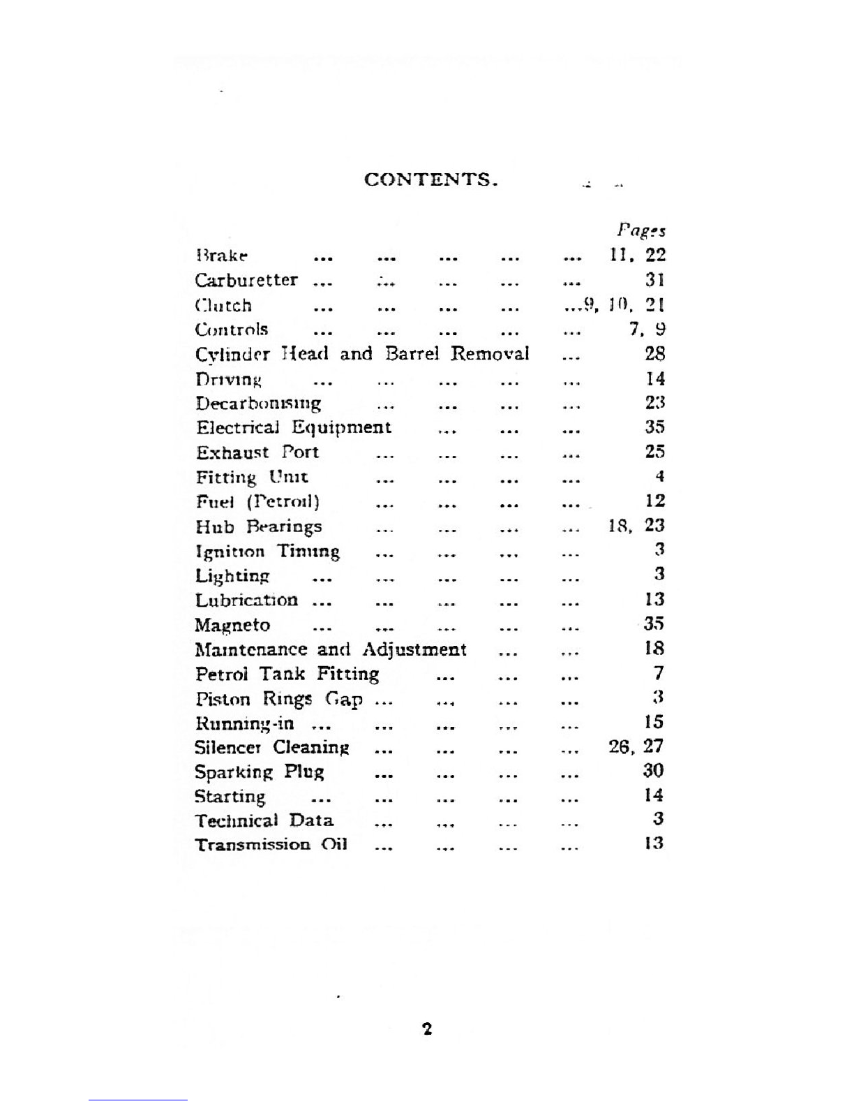
Table of contents
Other BSA Bicycle manuals
BSA
BSA 1971 B25SS Gold Star Instruction manual
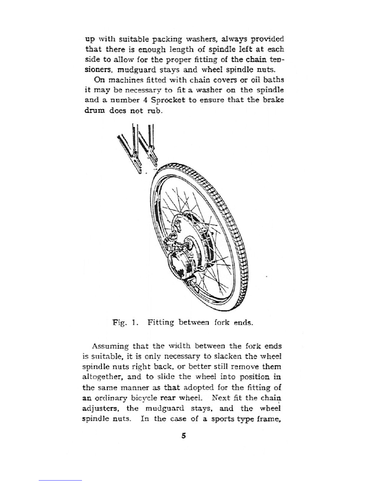
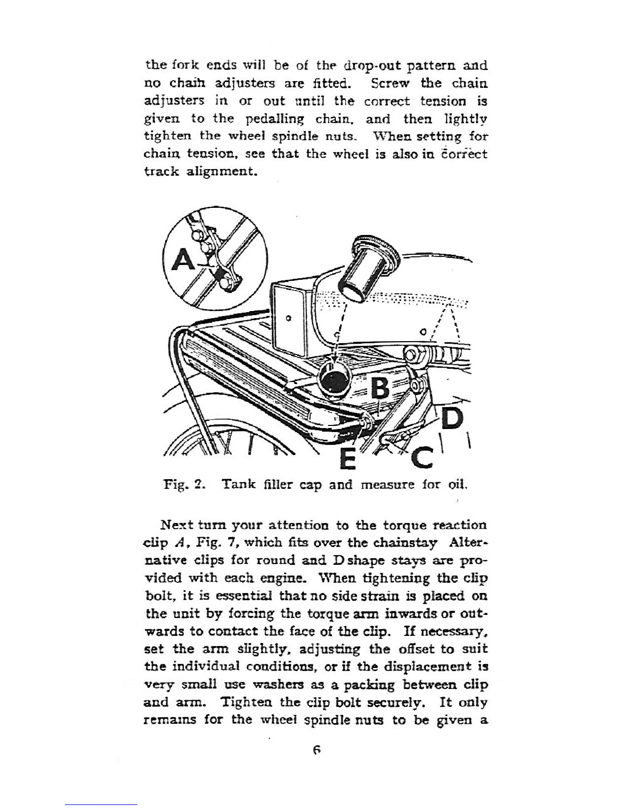
BSA Winged Wheel W1 User manual
RAMBO
RAMBO R1000X2M-FF-BFD manual
Vermeiren
Vermeiren SAFARI Maintenance manual
Velec
Velec A2/36V owner's manual
Cervélo
Cervélo S3 2019 Assembly manual
Festo
Festo EGSC-BS-KF Instructions & Operating
Gio Electric
Gio Electric H1 Volt owner's manual
GOGOBEST
GOGOBEST GM30 user manual
DAHON
DAHON CIAO - 2009 manual
Aprimatic
Aprimatic ONDA 500 Installation, use and maintenance instructions
MV Agusta
MV Agusta Lucky Explorer GRAVEL Manual for use and maintenance
Greyp
Greyp G6 Series user manual
Babboe
Babboe Carve-E user manual
Huka
Huka orthros manual
Xtracycle
Xtracycle Stoker 2021 Assembly manual
APRILIA
APRILIA DORSODURO 750 ABS 2015 manual
Alien
Alien E-Bike manual
ISLABIKES
ISLABIKES luath pro series owner's manual
ACID
ACID MUD ROOKIE SET 18 quick start guide