SoundwebTM
Soundwebtm 9088iiDSP System
Architects and Engineers Specifications
The Digital Signal Processor shall be a stand-alone unit of one rack space, capable of
providing a fully-functional system with 8 analogue inputs and 8 analogue outputs, without
the need for a dedicated, on-line computer system. The nalogue inputs shall have a
remotely-adjustable gain stage prior to /D conversion.
The system designer shall be provided complete flexibility in system configuration.
Line inputs or combination Microphone/Line inputs shall be provided, together with
channel-selectable 48 volt phantom power for the microphone inputs. The unit shall provide
a tamper-proof front-panel with no user-adjustable controls. Front panel LED indicators will
provide monitoring of signal presence, clip and network status. nalogue/Digital/ nalogue
conversion shall be by 24-bit -D converters and 24-bit D- converters to provide
maximum operating headroom and performance. The Dynamic Range shall be 105dB
minimum (unweighted, 108dB -weighted), with a THD figure of less than 0.01%.
Optional ES/EBU Digital input/output cards shall be available, each card having 2 stereo
inputs and 2 stereo outputs. Input sample rates shall be accepted from digital sources with
rates from 32kHz to 96kHz, and the user shall be able to select output sample rates of
44.1kHz, 48kHz, 88.2kHz, 96kHz or any sample rate between 32KHz and 96KHz using
external clock synchronisation. Clock synchronisation shall be possible with the first digital
input, the internal clock or an external word clock on a BNC connector.
Input and Output connections are provided via modular, Phoenix/Combicon style hardware.
Mating connectors (Phoenix/Combicon MSTB 2.5/6-ST-5.08 or equivalent) shall be supplied
with each unit on delivery or in advance.
The Signal Processor shall also be networkable over Category 5 cable (as established in the
TI /EI -568-B standard), to provide 8 channels of audio signals and control data routing
between processors for system expansion or communication. This network shall be
terminated on RJ-45 connectors, and be stable over distances up to 1000 feet between units.
There shall be available a fibre-optic converter to extend this distance to 1.2 miles. The
network shall allow system expansion at a later date through the addition of further Signal
Processors.
System Configuration shall be by a Personal Computer, which may be disconnected after
configuration without affecting installed operation of the unit. Up to 12 System
Configurations shall be stored in each processing device, and these configurations shall not
be limited by factory-only presets or pre-determined processing. It shall be possible to
configure a number of system presets, which may be recalled at any time via the PC or
external control devices.
The units software shall provide a palette of audio processing objects for use in system
designs to include, but not be restricted to: utomatic Microphone Mixers, mbient
Noise Compensators, Crossovers, Compressors, Gates, Duckers, Expanders, Limiters,
Gain blocks, Graphic Equalisers, Parametric Equalisers, Stereo Parametric Equalisers,
Filters, Metering points, Delays, Mixers, Matrix Routers, Matrix Mixers, Source Matrices,
Tone Generators, and Source Selectors. The software shall provide the facility to
construct user-defined control panels incorporating elements of the processing object
parameter controls. Multi-level password-based security shall protect the integrity of the
system.
The device configuration window shall provide a DSP gauge to inform the designer as to
the percentage of DSP usage. The system design software shall be compatible with either
Windows 95 or Windows NT4, 32 bit operating systems.
The software shall provide a facility to create personalised, custom processing objects for
use in system designs, with provision for intellectual property cloaking via Macros.
It shall be possible to connect standard potentiometers and switches or control voltages
to 8 control input ports to allow non-technical operators to change system presets or
variable parameters. n additional 8 control output ports shall provide logic outputs for
purposes of signal indication, external switching systems, or other similar system control
applications. n opto-isolated failsafe indicator shall be provided on an open-collector
output.
Two RS-232 ports shall be provided to allow control of the unit from Multimedia Systems
such as MX, Crestron, Dataton, venger or other PC devices communicating in a serial
mode, as well as independent, simultaneous control and programming from a PC
operating Soundweb Designer software. The RS232 port on any device shall provide
access to all devices that are properly networked together. It shall be possible to use
multiple PCs connected to separate signal processors in a network to control the system.
It shall also be possible to remotely control the system network using a PC & modem to
connect over telephone lines to another modem connected to the system network.
To aid in system management, the software shall provide a method of event logging so
that system diagnostics are available. This event log shall include failures, warnings and
information notices, and shall display the time of the event occurrence and the device to
which the event applies and the design file originally loaded.
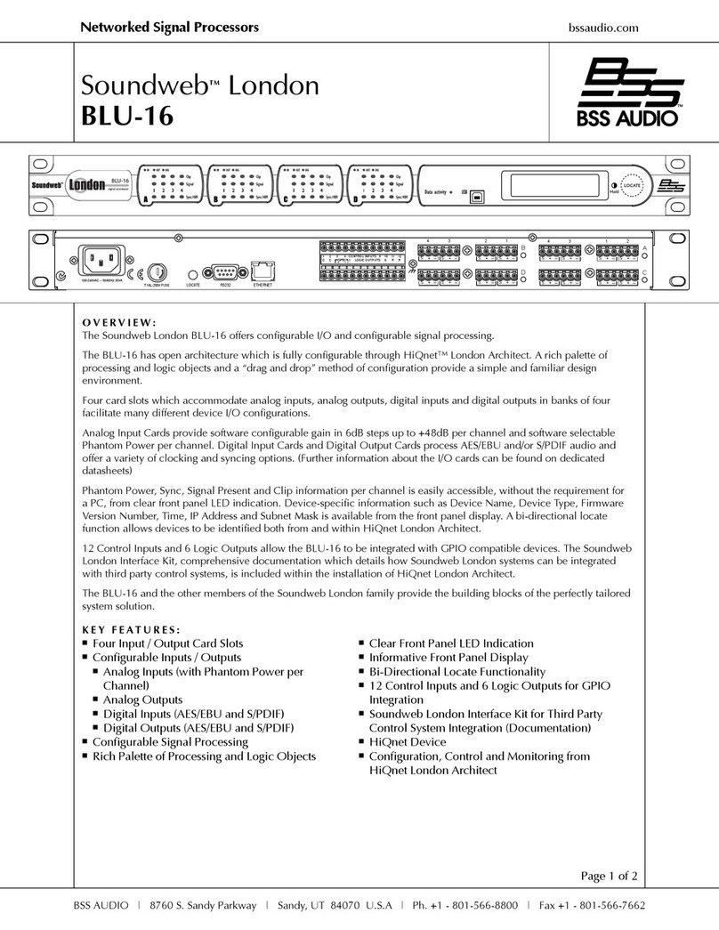
»8 Analogue Mic/Line Inputs
and 8 Analogue Outputs
»Optional AES/EBU digital
input/output (2 stereo)
cards with e ternal word
clock input
»Standalone unit with
200MIPS of DSP resource
»Integral multivoltage PSU
(85V - 270V AC)
»Analogue Control ports for
GPI hardware interfacing
eg faders, switches & LEDs
»Front and rear access
RS232 ports for PC control
»Integral memory holds up
to12 DSP system designs.
»Optional lacing bar to
secure cabling
Overview
The Soundweb 9088iiDSP unit is the heart of the Soundweb system.
s a standalone single rack space device it has all the facilities
required for a sound system processor; 8 inputs, 8 outputs, a DSP
engine, networking for connection and signal distribution to other
Soundweb units, analogue GPI control interfacing, and RS232 ports
for external control by PC or Panja/Crestron type systems. Plug in an
audio source, an amplifier, and speakers and you are away.
ll the facilities are included in a 9088ii, there is no additional
Soundweb system hardware required to begin building physical
systems. The only option decision to make is the choice of line input,
mic/line input cards or ES/EBU Digital input/output cards. Each
digital card accepts 2 stereo inputs at sample rates from 32kHz to
96kHz, and can output at 44.1, 48, 88.2, and 96kHz. When digital
inputs are used, the analogue outputs remain in use as a mirror
version of the digital output.
Each Soundweb 9088ii can typically hold up to 12 completely
different system designs in its own memory. Programming the unit is
accomplished via the Soundweb Designer software, available free of
charge from the BSS udio website (www.bss.co.uk)
For safety-critical systems, the Soundweb 9088ii has an opto-isolated
output which functions as a watchdog. The opto-isolator conducts
when power is applied to the unit and the software is functioning
correctly but, stops conductingin the event of a power failure or
other fault. This function can be used to trigger alarm systems or to
construct redundant systems.


