Motor-driven blocking device EasyBlocker
Installation instruction 108320
1 Introduction
1.1 General information
The blocking device serves to mechanically lock doors in order to avoid unintended entry of specially
activated security areas in connection with a burglar alarm system or to refuse access to unauthorized
persons for access control applications. This way, the motor-driven blocking device is part of a control
unit in order to fulfill any unavoidability.
It is possible to connect the blocking device to almost any system due to its flexible function. For access
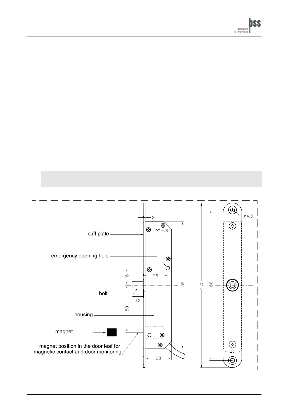
control applications it is possible to monitor the status of the door via an integrated magnetic contact. In
this case, the blocking device only closes when the door had been closed.
The blocking device is available in 2 versions:
Standard version (VdS - G 196 089) Battery version (VdS - G 197 051)
in relation with wired security systems in relation with radio burglar alarm systems
Item No Description Item No Description
108320.0 with magnetic contact, 3.5 m cable 108320.2 with magnetic contact, 3.5 m cable
108320.02 with magnetic contact, 10 m cable 108320.22 with magnetic contact, 10 m cable
108320.1 without magnetic contact, 3.5 m cable 108320.3 without magnetic contact, 3.5 m cable
108320.12 without magnetic contact, 10 m cable 108320.32 without magnetic contact, 10 m cable
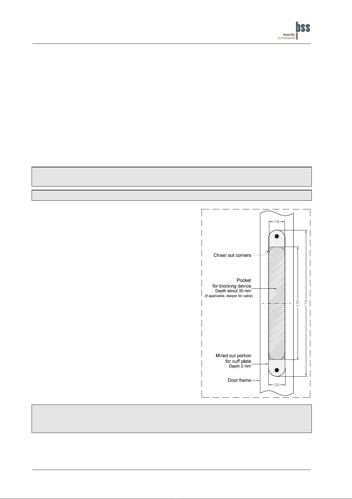
1.2 Mechanic assembly / Safety
Due to the robust assembly made of plastic and stainless steel, a high reliability and durability of more
than 500'000 cycles is being achieved. If the blocking device fails, there are electrical and mechanical
emergency opening options available.
1.3 Features of the blocking device
• VdS - Class C
• Low noise
• Quiescent current demand for a standard version of type 1.2 mA
• Quiescent current demand for a battery version of type 27 µA
• Integrated magnetic contact VdS class B (G 197 541)
• Feedback signal of the bolt position
• Bolt exchangeable
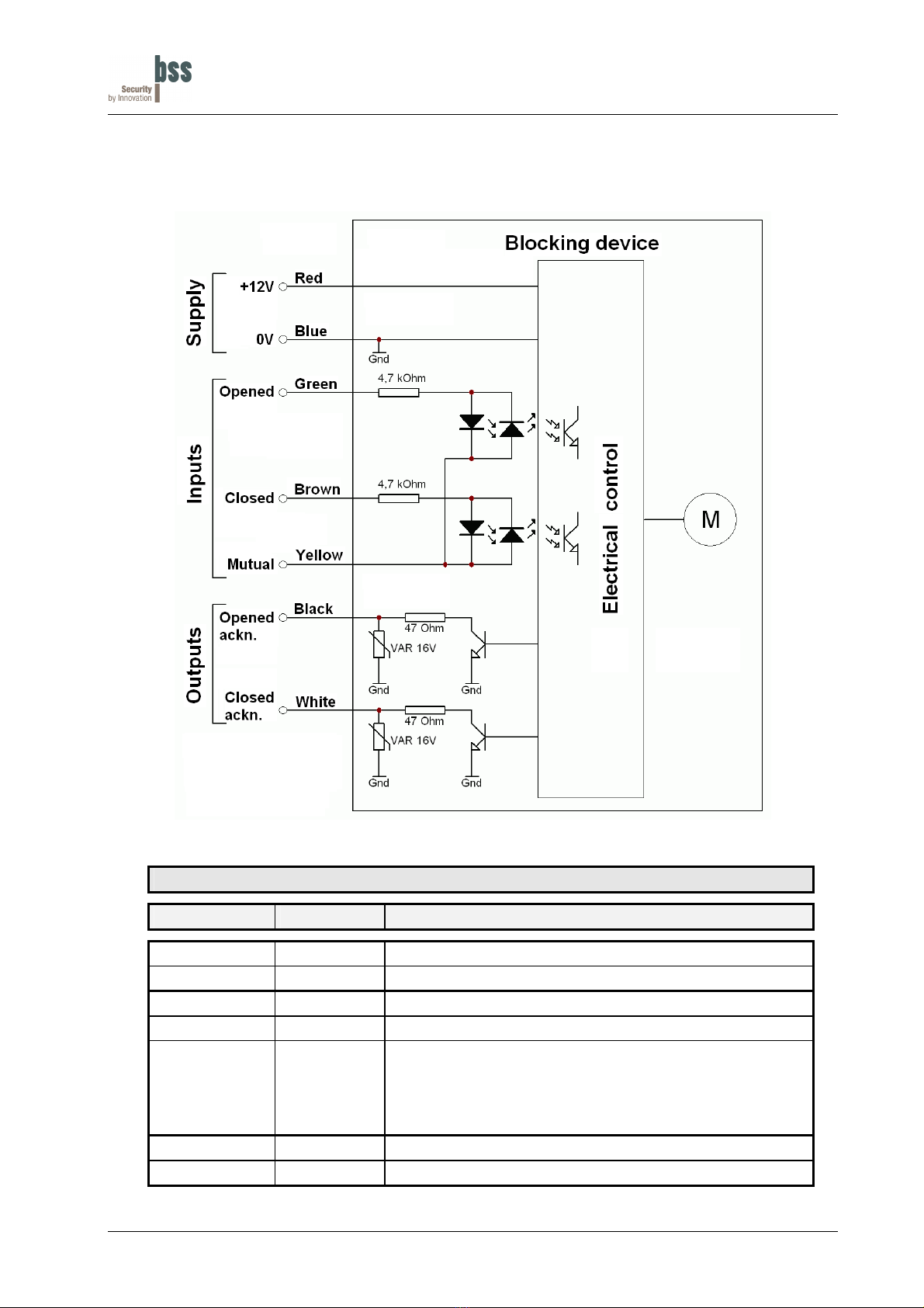
• To be connected to almost any system
• Drive with static or dynamic signals
• Several blocking devices can be connected in parallel or it is possible to implement a sequence control
• Integrated intelligent control
• Several closing trials, switching off when blocking
• Stable plastic construction
• Stainless steel cuff plate
• Easy installation in the door frame. Only the counterpart will be installed to the door leaf.
108320Err_ENG.doc version 6.0a / 06.04.2016 page 3