NGTeco NG-D2310 Series User manual

Installation Guide
Model: NG-D2310 Series
Lock Body: American Deadbolt
Version: 1.0
English

Important Notes
Please read this Installation Guide carefully and contact the Customer Care for any
installation queries.
It is recommended that installation be carried out by a professional technician to
prevent any potential service charges that can occur due to incorrect installation.
Four alkaline AA batteries (not included) are required to power on the device. Non-alkaline
and rechargeable batteries are “NOT RECOMMENDED” .
1.
2.
3.
Do not remove the batteries from the lock when it is working.
4.
Batteries must be replaced immediately when the lock prompts the "The battery is used
up, please replace it" warning.
5.
Mechanical keys are included in the lock for manual unlocking. Please store the keys
in a secure location.
6.
Table of Contents
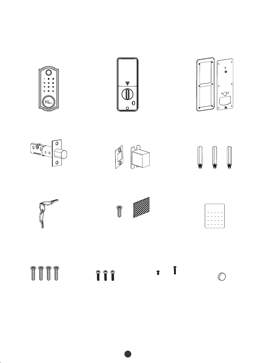
What's in the Box.............................................................................................................1
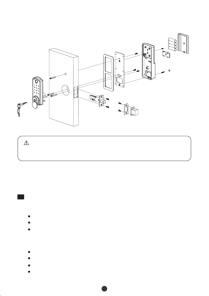
Installation Diagram.......................................................................................................2
Installation Procedure....................................................................................................2
1. Prepare Door for Installation..................................................................................................................2
2. *Drill Holes on the Door...........................................................................................................................3
3. Install the Deadbolt..................................................................................................................................4
4. Install the Strike Plate and Box..........................................................................................................5
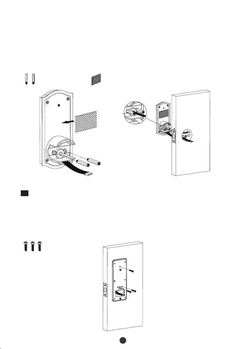
5. Install the Outdoor Assembly.............................................................................................................5
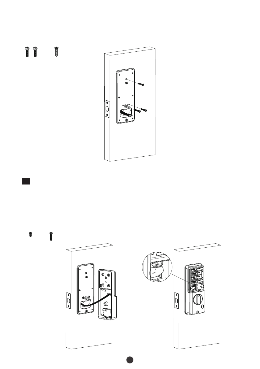
6. Install the Mounting Plate....................................................................................................................6
7. Install the Indoor Assembly....................................................................................................................7
8. Physical Testing.........................................................................................................................................8
9. Install the Batteries and Cover..............................................................................................................8

1
What's in the Box
Mounting Plate
Deadbolt Strike Plate and Box
Outdoor Assembly Indoor Assembly
User Files
Manual
Studs
Keys
Note: Screws for doors with a thickness of 35 to 55 mm are included in the standard package.
Plug
Screws A
Deadbolt/Strike
Indoor Assembly
Screws B
Mounting Plate
Double-sided
Tape
Screw C
Mounting Plate (optional)
Screw D Screw E

When the door is locked, leave enough space for the deadbolt to extend into the
doorframe.
Installation Diagram
2
Installation Procedure
Important Note
To stabilize the Outdoor Assembly, you can use either the provided Double-sided
Tape or Stud. Stud requires an additional hole to be drilled.
1Prepare Door for Installation
1. To ensure proper installation of the smart lock, make sure the following criteria are
followed:
2.
Check the door status. Make sure the doorframe is aligned with the door.
There are no obstructions stuck in the doorframe.
Check your door/frame dimensions to make sure that they fit the following measurements:
Diameter of Cross Bore: 55 mm
Backset: 60 mm or 70 mm
Diameter of Door Hole: 25 mm
Door Thickness: 35 to 55 mm
Door
Keys
Studs
Optional
Outdoor
Assembly
Strike Plate
and Box
Deadbolt
Screw E
Screw D
Battery
(not included)
Indoor
Assembly
Battery
Cover
Mounting
Plate
Plug
Back Cover
Screws B
Screws A
Deadbolt/Strike

Diameter of
Cross Bore:
55 mm
3
2*Drill Holes on the Door
Place the Installation Template at the desired Cylinder height.
Mark for the holes to be drilled and drill the marked places.
1.
2.
Important Note
It is not necessary to drill holes on the door. We have already provided Double-
sided Tape in the kit to help with the stabilization of the lock during installation.
If you still want to improve stability, use the mounting template to drill the
holes.
Door Thickness:
35 to 55 mm
Backset:
60 mm or
70 mm
Diameter of
Door Hole:
25 mm
Desired Cylinder height
Door thickness
35 to 55mm
60/70mm
Backset
Center line of the Cylinder

60mm
35~55mm
4
3Install the Deadbolt
Adjust the Deadbolt (if needed)
1.
Backset is the distance from the edge of the door to the center of the hole drilled on the
door. The default Backset is 60mm, but if you want to change the Backset to 70mm, grasp
body and twist the Faceplate as shown below:
Rotate the Faceplate
By default, the metal shaft twists over the center as shown:
60mm backset
Press the Bolt inside the Latch
70mm backset
Pull-out the Faceplate Rotate it back
Before installing, make sure that the deadbolt is in the unlocked position and that
the arrow is facing upwards.
Fix the Deadbolt with Screws A.
2.
3.

4Install the Strike Plate and Box
Make sure that the Strike Box is aligned with the Deadbolt. Then, use the Installation
Template to drill holes.
1.
Align the Strike Plate and Box with the drilled holes and fix them with Screws A.
2.
Screws A
35MM
(1-48/127 “)
58(MM)
(2-36/127 “)
29(MM)
(1-18/127 “)
21(MM)
(215/254 “)
27(MM)
(1 19/64 “)
Depth 2(MM)
(10/127 “)
14MM
(70/127 “)
5
5Install the Outdoor Assembly
There are two methods to install the Outdoor Assembly.
vMethod 1: Installation with Stud
Place the Stud on the Mounting Plate of the Outdoor Assembly.
Make sure the highlighted Spindle is in the horizontal position, as shown below.
1.
2.
Attach the Outdoor Assembly to the door by inserting the cable through the drilled holes.
4.
Route the cable through the opening below the bolt.
3.
Studs

vMethod 1: Installation with Stud
Route the cable through the hole on the Mounting Plate.
Place the Mounting Plate on to the door and use Screws B to secure them.
1.
2.
Screws B
6
6Install the Mounting Plate
According to the previously selected Outdoor Assembly Installation method in Step 5, choose
the Mounting Plate installation method.
vMethod 2: Installation with Double-sided Tape
Remove the double-sided tape from the outdoor assembly's mounting plate.
Make sure that the highlighted Spindle is in the horizontal position, as shown below.
1.
2.
Attach the Outdoor Assembly to the door by inserting the cable through the drilled holes.
4.
Route the cable through the opening below the bolt.
3.
Studs
Note: The method of installation with stud is more stabilized, the Installation with
Double-sided Tape is the second choice.
Double-sided
Tape

7
7Install the Indoor Assembly
Connect the cable to the port on the back of Indoor Assembly.
1.
Install the Indoor Assembly on the Mounting Plate in the proper location. Then attach
the Indoor Assembly using Screw D and Screw E.
2.
Note: No matter left or right opening direction, the knob dot must be vertical, after
installing the batteries, please turn the knob dot to horizon.
vMethod 2: Installation with Double-sided Tape
Insert the cable through the Mounting Plate's hole.
Install the Mounting Plate on the door and fasten it with Screws B and Screw C.
1.
2.
Screws B Screw C
Screw D Screw E

8
8Physical Testing
Rotate the Knob to check if the Deadbolt works properly.
1.
Insert the Key and rotate to check if the Deadbolt works properly.
2.
Note: If the Knob or Key cannot control the Deadbolt correctly, please read the Installation
Procedure carefully and re-install the lock.
9Install the Batteries and Cover
Insert four Alkaline AA batteries into the lock and cover them with the battery cover.
1.
Turn the KNOB to the horizontal position when the voice prompt "Di" appears and the
button is solid on, then the voice "Successful" appears.
2.
Enter 7 to enable Auto Re-lock Mode (if need).
3.

Version: 1.0
English
User Manual
Model: NG-D2310 Series

Important Notes
Please read this User Manual carefully or contact the Customer Care for any queries.
It is recommended that installation be carried out by a professional technician to prevent
any potential service charges that can occur due to incorrect installation.
Four alkaline AA batteries (not included) are required to power on the device. Non-
alkaline and rechargeable batteries are “NOT RECOMMENDED” .
1.
2.
4.
Do not remove the batteries from the lock when it is working.
5.
Batteries must be replaced immediately when the lock prompts the "The battery is
used up, please replace it" warning.
6.
For manual unlocking, the lock is also provided with mechanical keys. Please keep
the keys in a safe place.
7.
Fingerprint positioning tips:
8.
Note: Please use the correct method when pressing your fingers onto the fingerprint
reader for registration and identification. Our company will assume no liability for
recognition issues that may result from incorrect usage of the product. We reserve the
right of final interpretation and modification concerning this point.
Recommended fingers: Index, middle, or ring fingers; avoid using the thumb or pinky, as it is
difficult to accurately press onto the fingerprint reader using those.
Too low Too close to the edge
Vertical
After unlock by APP, fingerprint or password, please do not verify again.
9.
Please make sure no strong magnetic object closes to the smart lock.
3.
NGTeco could not guarantee the exact consistency between the real product and the
stated information in this handbook due to constant system and product modifications..
10.

Table of Contents

Product Overview
Introduction:
The maximum user capacity is 100. The maximum Fingerprint/Password capacity is
50. The password length is 6 to 8 digits.
Note: The first and second registers will be set as administrators by default, and the
first administrator must be password.
The Owner is the person who owns the lock, and registers in NGTeco Home App, and
has all the privileges.
The Admin can unlock via Fingerprint, Password or App. Also, the Admin can add or
delete normal users, and manage all the lock settings.
1.
Product Features
2.
3.
Fingerprint Sensor
Touchscreen Area
Mechanical Key Hole
Micro-USB Interface
Battery Cover
Battery Slot
Switch Button
Knob
Random Password: Users may enter their password along with some random digits before
or after the actual password for password protection. The maximum number of entered
digits must be less than or equal to 16. For example, if the correct password is 202112, then
the random password can be 89202112807, 2021122363, 389202112, etc.
Auto Re-lock Mode: The smart lock re-locks according to shock, sometimes, if closing the
door too light, the smart lock will not re-lock, need some shock.
Passage Mode: This function is to keep the door always unlocked, which is suitable for
meeting rooms and places with no access restriction.
1
Reset Button
Cable Port
Knob
Normal Users can unlock via Fingerprint, Password or App, and check the access
records.
4.
Note: Some regular passwords cannot be set as password, if it occurs, please use a
different password. Such as 123456, 12345678, 88888888, 11111111, etc.
Volume Setting: The volume can be set to high/low or silent modes.

To pair the device, open the Bluetooth on your phone and get near to the smart lock.
2.
Low Battery Warning: When the battery is low, the lock prompts "Battery is used up,
please replace it" after being turned on. Then, please replace the batteries immediately.
Emergency Charging: The bottom of the outdoor assembly is provided with a Micro-USB
port. Use a power bank to charge the lock when it is out of power.
Emergency Mechanical Key: If the lock has any electronic malfunction, the mechanical
key is used to open the door during emergency situations.
Bluetooth Communication: The lock is designed to communicate over Bluetooth, and
once connected, it can be controlled from your smartphone.
Lock Setup
Note: All the registered user data will be deleted and restored to the factory default settings.
Press and hold the Reset button for 3 seconds, until you hear the audio prompt “Please
verify administrator”, then enter verify administrator with password or fingerprint. After a
few seconds, the lock will prompt “Initialization Succeed”. If no administrator, do not need
verify administrator.
Reset the Lock
1
vMethod 1:
2Pair the Lock with App
Search the “NGTeco Home” App in Apple App Store or Google Play Store and download
the App to your mobile phone. Open the “NGTeco Home” App and log in with your
account. If you do not have an account, create an account with your phone number or
Email ID.
1.
2
Unauthorized Access Alert: lf the verification fails for 5 times consecutively, the lock will
generate the alarm, then the lock cannot be operated within 180 seconds.
Press the Reset button for 3 seconds, then enter "123234345455" and press to initialize directly.
vMethod 2:
vMethod 3: (if paired with App)
Tap the right up corner button, and then tap the Remove Device button at the bottom
of the user interface, then the lock will prompt "Initialization Succeed", press reset button
until you hear prompt "Initialization Succeed".

3
Touch the keypad to activate the lock, enter 3 to enable Bluetooth, and the App
will search the nearby devices automatically.
3.
Tap the “+” button of the corresponding lock, then your phone will connect the smart
lock via Bluetooth.
4.
Note: Make sure the lock has registered an administrator. Turn on Bluetooth on your
smartphone, and stay near the lock (within 10 meters without any obstacle).
Program the Features on the Lock
3
It is recommended to use the NGTeco Home App to manage your lock. If you don't have a
smartphone or don't want to use the App, you can use the following programming
instructions.
Features Operations
Add administrator
Press or press reset button until you hear a beep prompt.
To register the first administrator, use a password of 6 to 8 digits.
1.
2.
3. To register the second administrator, provide a 6 to 8 digit
password or use your fingerprint.
Add normal user
Press for 2.5second, or press reset button for 2 seconds, verify
administrator.
1.
2. Enter a 6 to 8 digit password or use your fingerprint.
Volume Setting
Default high volume, enter 333 first time, the volume changes to
low, enter 333 second time, the volume changes to mute, enter
333 third time, the volume changes to high.
Language Setting
Left or Right
Direction Setting
Bluetooth Enable
Change Password Enter 5 to change normal user password, administrator password
cannot be changed.
Delete user
Press for 2.5second, or press reset button for 2 seconds, verify
Press for 2.5 second again.
1.
2.
3. 1: delete fingerprint of all of user; 2: delete password of all of
user; 3: delete all of users.
administrator.
To switch between Chinese and English, dial 311 .
Enter 301 to change left or right open direction.
Enter 3 to enable Bluetooth configuration mode.
Delay Lock Mode
Enter 6 1 time, 1 long beep and 1 short beep, 15 seconds delay.
1.
Enter 6 2 times, 1 long beep and 2 short beeps, 30 seconds delay.
2.
Enter 6 3 times, 1 long beep and 3 short beeps, 45seconds delay.
3.
Enter 6 4 times, close this mode and change to Geomagnetic
Detect Mode.
4.

4
Basic Operations
Unlock the Door with Fingerprint
Unlock the Door with Password
Touch the keypad to
activate the lock
Press the registered
fingerprint on the
fingerprint sensor
Push the door or
rotate the handle
down to open
Enter the registered
password and press the
key to confirm
Push the door or
rotate the handle
down to open
Note: Users may enter any random number along with actual password to prevent password
disclosure. The maximum length of the random password is 16 digits.
Unlock the Door with App
Turn on Bluetooth on
your smartphone
Open the App and press
the UNLOCK button
Push the door or
rotate the handle
down to open
Note: When unlocking via Bluetooth, please stay near the lock (within 10 meters without
obstacles).
Passage Mode
Press 5 and 8 to unlock
by fingerprint,
password, or APP
Enable passage mode
Press the Switch Button
of the indoor assembly
Disable passage mode
Note: If you unlock the mode by turning the knob, the mode will still be enabled, and you
will need to verify it with someone outside.
Calibrate
Automatically
Lock
Enter 7 and verify administrator to calibrate automatically lock in
some situation that the door lock does not automatically lock.

This device complies with Part 15 of the FCC Rules. Operation is subject to the following two
conditions: (1) This device may not cause harmful interference, and (2) this device must accept
any interference received, including interference that may cause undesired operation.
This equipment has been tested and found to comply with the limits for a Class B digital device,
pursuant to Part 15 of the FCC Rules. These limits are designed to provide reasonable protection
against harmful interference in a residential installation. This equipment generates, uses, and
can radiate radio frequency energy and, if not installed and used in accordance with the
instructions, may cause harmful interference to radio communications. However, there is no
guarantee that interference will not occur in a particular installation. If this equipment does
cause harmful interference to radio or television reception, which can be determined by
turning the equipment off and on, the user is encouraged to try to correct the interference by
one or more of the following measures:
Warning:
Connect the equipment into an outlet on a circuit different from that to which the
receiver is connected.
IMPORTANT! Any changes or modifications not expressly approved by the party responsible
for compliance could void the user's authority to operate the equipment.
Reorient or relocate the receiving antenna.
Increase the separation between the equipment and receiver.
Consult the dealer or an experienced radio/T V technician for help.
FCC RF Radiation Exposure Statement:
This Transmitter must not be co-located or operating in conjunction with any other
antenna or transmitter.
This equipment complies with RF radiation exposure limits set forth for an uncontrolled
environment.

1600 Union Hill Road Alpharetta, GA 30005
E-mail: service.ng@ngteco.com
www.ngteco.com
Copyright©2022 NGTECO CO., LIMITED. All rights reserved.
Table of contents
Other NGTeco Door Lock manuals
Popular Door Lock manuals by other brands

DynaLock
DynaLock 3101B installation instructions

LOCKLY GUARD
LOCKLY GUARD ATHENA 228SL installation guide

INVITED
INVITED SMARTLOCK Installation guide & user manual

Schlage
Schlage Artus quick start guide

Philips
Philips EasyKey 7000 Series user manual

Biometrics Direct
Biometrics Direct BioCert FS-100 instruction manual