manuals.online logo
Brands
  1. Home
  2. •
  3. Brands
  4. •
  5. SMC Networks
  6. •
  7. Controllers
  8. •
  9. SMC Networks 25A-LEFS Series User manual

SMC Networks 25A-LEFS Series User manual

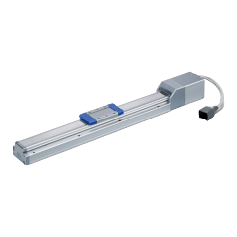
Electric Actuator/Slider Type
Ball Screw Drive
Series 25A-LEFS
LEFS16, 25, 32, 40
Step Motor (Servo/24 VDC) Servo Motor (24 VDC)
Applicable stroke table Standard
50 100 150 200 250 300 350 400 450 500 550 600 650 700 750 800 850 900 950
1000
Manufacturable
stroke range [mm]
LEFS16 — — — — — — — — — — 50 to 500
LEFS25 — — — — — — — — 50 to 600
LEFS32 — — — — 50 to 800
LEFS40 — — 150 to 1000
*Strokes are manufacturable in 1 mm increments. Refer to the manufacturable stroke range. However, strokes other than those shown above are produced
as special orders. Consult with SMC for lead times and prices.
How to Order
rMotor type
Symbol
Type
Applicable size Compatible
controllers/
driver
LEFS16 LEFS25 LEFS32 LEFS40
Nil Step motor
(Servo/24 VDC) 
LECP6
LECP1
LECPA
LECPMJ
AServo motor
(24 VDC)   — — LECA6
tLead [mm]
Symbol
LEFS16 LEFS25 LEFS32 LEFS40
A10 12 16 20
B5 6 8 10
e
Motor mounting position
Nil In-line
R
Right side parallel
L
Left side parallel
wSize
16
25
32
40
yStroke [mm]
50 50
to to
1000 1000
*Refer to the applicable stroke table.
Model
Stroke
[mm]
Caution
[CE-compliant products]
qEMC compliance was tested by combining the electric actuator LEF series and the controller
LEC series.
The EMC depends on the configuration of the customer’s control panel and the relationship with
other electrical equipment and wiring. Therefore conformity to the EMC directive cannot be
certified for SMC components incorporated into the customer’s equipment under actual
operating conditions. As a result it is necessary for the customer to verify conformity to the EMC
directive for the machinery and equipment as a whole.
wFor the servo motor (24 VDC) specification, EMC compliance was tested by installing a noise
filter set (LEC-NFA).
Refer to the WEB catalog for the noise filter set. Refer to the LECA Operation Manual for
installation.
[UL-compliant products]
When conformity to UL is required, the electric actuator and controller/driver should be used with a
UL1310 Class 2 power supply.
Series compatible with
secondary batteries
The actuator and controller/driver are sold as a package.
Confirm that the combination of the controller/driver and the actuator is correct.
<Check the following before use.>
q
Check the actuator label for model number (after "25A-"). This matches the controller/driver.
wCheck Parallel I/O configuration matches (NPN or PNP).
*Refer to the operation manual for using the products. Please download it via our website, http://www.smcworld.com
RoHS
®
q w
qAccuracy
Nil Basic type
H
High precision type
25A-LEFS 25
w
200
y
6N
!0
S
i
1
o
R
e
H
q r
B
t u
1
!1 !2
153
25A-P-B-P153-web修正-CS3e.indd 153 14.10.10 5:01:34 PM
A
uMotor option
Nil Without option
BWith lock
iActuator cable type*1
Nil Without cable
SStandard cable*2
R
Robotic cable (Flexible cable)
*1 The standard cable should be used on fixed
parts. For using on moving parts, select the
robotic cable.
*2 Only available for the motor type “Step
motor”.
!1
I/O cable length [m]
*1
, Communication plug
Nil
Without cable (Without communication plug connector
*3
)
11.5
33*2
55*2
S
Straight type communication plug connector
*3
T
T-branch type communication plug connector
*3
*1 When “Without controller/driver” is selected
for controller/driver types, I/O cable cannot
be selected. When the I/O cable is required,
order it separately.
*2 When “Pulse input type” is selected for
controller/driver types, pulse input usable
only with differential. Only 1.5 m cables
usable with open collector.
*3 When “CC-Link direct input type” is selected
for controller/driver types, I/O cable is not
included. Only “Nil”, “S” or “T” can be
selected.
!2 Controller/Driver mounting
Nil Screw mounting
DDIN rail mounting*
*DIN rail is not included. Order it separately.
oActuator cable length [m]
Nil Without cable
11.5
33
55
88*
A10*
B15*
C20*
*
Produced upon receipt of order (Robotic cable only)
!0 Controller/Driver type*1
Nil Without controller/driver
6N LECP6/LECA6
(Step data input type)
NPN
6P PNP
1N LECP1*2
(Programless type)
NPN
1P PNP
MJ LECPMJ*2 *3
(CC-Link direct input type) —
AN LECPA*2 *4
(Pulse input type)
NPN
AP PNP
*1 For details about controllers/driver and
compatible motors, refer to the compatible
controllers/driver below.
*2 Only available for the motor type “Step motor”.
*3 Not applicable to CE.
*4 When pulse signals are open collector, order
the current limit resistor (LEC-PA-R-l)
separately.
Compatible Controllers/Driver
Type
Step data
input type
Step data
input type
CC-Link
direct
input type
Programless type Pulse input type
Series LECP6 LECA6 LECPMJ LECP1 LECPA
Features Value (Step data) input
Standard controller CC-Link direct input
Capable of setting up operation (step data)
without using a PC or teaching box
Operation by pulse signals
Compatible motor
Step motor
(Servo/24 VDC)
Servo motor
(24 VDC)
Step motor
(Servo/24 VDC)
Maximum number of step data
64 points 64 points 14 points —
Power supply voltage
24 VDC
*Copper and zinc materials are used for the motors, cables, controllers/drivers.
*
Specifications and dimensions for the
25A-series are the same as standard products.
Motor mounting position:
Right side parallel
Motor mounting position:
In-line
154
Electric Actuator/Slider Type
Ball Screw Drive Series 25A-LEFS
25A-P-B-P154-web修正-CS3e.indd 154 14.10.9 7:30:15 PM
Air Cylinders
Air Grippers
Directional
Control Valves
Related
Products
Rotary
Actuators
Vacuum
Equipment
Air Preparation
Equipment
Air Filters/Pressure
Control Equipment
Fittings/Flow
Control Equipment
Detection
Switches
Fluid Control
Equipment
Electric
Actuators
Auto
Switches
Clean
Air Filters
A
Electric Actuator/Slider Type
Ball Screw Drive
Series
25A-LEFS
LEFS25, 32, 40
How to Order
RoHS
!0 Driver type
Compatible
drivers
Power supply
voltage (V)
Size
25 32 40
Nil
Without driver
—
A1
LECSA1-S
100 to 120
  —
A2
LECSA2-S
200 to 230

B1
LECSB1-S
100 to 120
  —
B2
LECSB2-S
200 to 230

C1
LECSC1-S
100 to 120
  —
C2
LECSC2-S
200 to 230

S1
LECSS1-S
100 to 120
  —
S2
LECSS2-S
200 to 230

*When the driver type is selected, the cable
is included. Select cable type and cable
length.
Example) S2S2:
Standard cable (2 m) + Driver (LECSS2)
S2 : Standard cable (2 m)
Nil : Without cable and driver
AC Servo Motor
Series compatible with
secondary batteries
Applicable stroke table Standard
50
100 150 200 250 300 350 400 450 500 550 600 650 700 750 800 850 900 950
1000
Manufacturable
stroke range
[mm]
LEFS25 ————————
50 to 600
LEFS32 ————
50 to 800
LEFS40 — — 
150 to 1000
*Strokes are manufacturable in 1 mm increments. Refer to the manufacturable stroke range. However,
strokes other than those shown above are produced as special orders. Consult with SMC for lead times
and prices.
Model
Stroke
[mm]
rMotor type
Symbol
Type
Output [W]
Actuator size
Compatible drivers
S2*1
AC servo motor
(Incremental
encoder)
100 25 LECSA-S1
S3 200 32 LECSA-S3
S4 400 40 LECSA2-S4
S6*1
AC servo motor
(Absolute
encoder)
100 25
LECSB-S5
LECSC-S5
LECSS-S5
S7 200 32
LECSB-S7
LECSC-S7
LECSS-S7
S8 400 40
LECSB2-S8
LECSC2-S8
LECSS2-S8
*1 For motor type “S2” and “S6”, the compatible driver part
number suffixes are “S1” and “S5” respectively.
*2 For details about the driver, refer to the WEB catalog.
e
Motor mounting
position
Nil In-line
R
Right side parallel
L
Left side parallel
iCable type*1, *2
Nil Without cable
SStandard cable
RRobotic cable
(Flexible cable)
*1 The motor and encoder cables are
included. (The lock cable is also
included when the motor with lock
option is selected.)
*2 Standard cable entry direction is
· Parallel: (A) Axis side
· In-line: (B) Counter axis side
wSize
25
32
40
tLead [mm]
Symbol
LEFS25 LEFS32 LEFS40
A12 16 20
B6 8 10
o
Cable length
*
[m]
Nil Without cable
22
55
A10
*
The length of the encoder,
motor and lock cables are
the same.
uMotor option
Nil Without option
BWith lock
yStroke [mm]
50 50
to to
1000 1000
*Refer to the applicable
stroke table.
*Specifications and dimensions for the 25A-series are the same as standard products.
!1 I/O cable length [m]*3
Nil Without cable
H
Without cable (Connector only)
11.5
*3 When “Without driver” is selected for driver type,
only “Nil: Without cable” can be selected.
Refer to the WEB catalog if I/O cable is required.
25A-LEFS 32
w
R
e
H
q
S3
r
200
y
A2
!0
S
i
2
o
B
t u !1
qAccuracy
Nil
Basic type
H
High precision type
155
Compatible Drivers
Driver type
Pulse input type/
Positioning type
Pulse input type CC-Link direct
input type
SSCNET#type
Series LECSA LECSB LECSC LECSS
Number of point tables Up to 7 —
Up to 255 (2 stations occupied)
—
Pulse input   — —
Applicable network — — CC-Link SSCNET3
Control encoder Incremental
17-bit encoder
Absolute
18-bit encoder
Absolute
18-bit encoder
Absolute
18-bit encoder
Communication function
USB communication
USB communication, RS422 communication USB communication, RS422 communication
USB communication
Power supply voltage (V)
100 to 120 VAC (50/60 Hz)
200 to 230 VAC (50/60 Hz)
*Copper and zinc materials are used for the motors, cables, controllers/drivers.
25A-P-B-P155-web修正-CS3e.indd 155 14.10.10 5:02:30 PM
A
Series compatible with
secondary batteries
*Specifications and dimensions for the 25A-series are the same as standard products.
AC Servo Motor
How to Order
156
Electric Actuator/High Rigidity Slider Type
Ball Screw Drive
Series
25A-LEJS
LEJS40, 63
Compatible Drivers
Solid state auto switches should be ordered separately.
For details about auto switches, refer to page 164.
Applicable stroke table*4Standard
*4 Consult with SMC for non-standard strokes as they are produced as special orders.
*1 For motor type “S2” and “S6”, the compatible driver part number
suffixes are “S1” and “S5” respectively.
*2 For details about the driver, refer to the WEB catalog.
wSize
*6 The motor and encoder cables are included. (The lock
cable is included when the motor with lock option is
selected.)
*7 Standard cable entry is “(A) Axis side”.
*8 The length of the motor,
encoder and lock cables
are the same.
uCable type*5, *6, *7
i
Cable length [m]*5, *8
eMotor type*1
oDriver type*5
*5 When the driver type is selected,
the cable is included. Select cable
type and cable length.
Example)
S2S2: Standard cable (2 m) +
Driver (LECSS2)
S2 : Standard cable (2 m)
Nil : Without cable and driver
Applicable auto switches
D-M9N(V)-900, D-M9P(V)-900, D-M9B(V)-900
D-M9NW(V)-900, D-M9PW(V)-900, D-M9BW(V)-900
RoHS
Compatible drivers
Power supply voltage (V)
Nil Without driver —
A1 LECSA1-S100 to 120
A2 LECSA2-S200 to 230
B1 LECSB1-S100 to 120
B2 LECSB2-S200 to 230
C1 LECSC1-S100 to 120
C2 LECSC2-S200 to 230
S1 LECSS1-S100 to 120
S2 LECSS2-S200 to 230
Symbol Type Output
[W]
Actuator
size
Compatible
drivers *2
S2 AC servo motor
(Incremental encoder) 100 40 LECSA-S1
S3 AC servo motor
(Incremental encoder) 200 63 LECSA-S3
S6 AC servo motor
(Absolute encoder) 100 40
LECSB-S5
LECSC-S5
LECSS-S5
S7 AC servo motor
(Absolute encoder) 200 63
LECSB-S7
LECSC-S7
LECSS-S7
Nil Without cable
SStandard cable
RRobotic cable (Flexible cable)
Nil Without cable
22
55
A10
*3 Refer to the table
below for details.
tStroke [mm]*3
200
to
1500
Stroke
[mm]
Model 200 300 400 500 600 700 800 900 1000 1200 1500
LEJS40 —
LEJS63 —
yMotor option
Nil Without option
BWith lock
rLead [mm]
Symbol LEJS40 LEJS63
H24 30
A16 20
B8 10
40
63
Driver type
Pulse input type/
Positioning type
Pulse input type CC-Link direct
input type
SSCNET#type
Series LECSA LECSB LECSC LECSS
Number of point tables Up to 7 — Up to 255 —
Pulse input   — —
Applicable network — — CC-Link SSCNET3
Control encoder Incremental
17-bit encoder
Absolute
18-bit encoder
Absolute
18-bit encoder
Absolute
18-bit encoder
Communication function
USB communication
USB communication, RS422 communication USB communication, RS422 communication
USB communication
Power supply voltage (V)
100 to 120 VAC (50/60 Hz)
200 to 230 VAC (50/60 Hz)
*Copper and zinc materials are used for the motors, cables, controllers/drivers.
25A-LEJS 40 500
AH
w e rq t y u i o !0
qAccuracy
S2
Nil Basic type
H
High precision type
!0 I/O cable length [m]*9
Nil Without cable
H
Without cable (Connector only)
11.5
*9 When “Without driver” is selected
for driver type, only “Nil: Without
cable” can be selected.
Refer to the WEB catalog if I/O
cable is required.
25A-P-B-P156-web修正-CS3e.indd 156 14.10.9 8:40:31 PM
Air Cylinders
Air Grippers
Directional
Control Valves
Related
Products
Rotary
Actuators
Vacuum
Equipment
Air Preparation
Equipment
Air Filters/Pressure
Control Equipment
Fittings/Flow
Control Equipment
Detection
Switches
Fluid Control
Equipment
Electric
Actuators
Auto
Switches
Clean
Air Filters
A
Series compatible with
secondary batteries
How to Order
156-1
Electric Actuator/High Rigidity Slider Type
Ball Screw Drive
Series 25A-LEJS
AC Servo Motor
LEJS40, 63
Compatible
Compatible Drivers
Driver type
type
Series LECSS-T
Applicable network SSCNET3/H
Control encoder Absolute
22-bit encoder
Communication function
USB communication
Power supply voltage (V)
200 to 240 VAC (50/60Hz)
*Copper and zinc materials are used for the motors, cables, controllers/drivers.
Solid state auto switches should be ordered separately.
For details about auto switches, refer to page 164.
Applicable stroke table*4Standard
*4 Consult with SMC for non-standard strokes as they are produced as special orders.
Applicable auto switches
D-M9N(V)-900, D-M9P(V)-900, D-M9B(V)-900
D-M9NW(V)-900, D-M9PW(V)-900, D-M9BW(V)-900
RoHS
eMotor type*1
Symbol Type Output
[W]
Actuator
size
Compatible
driver *2
T6 AC servo motor
(Absolute encoder)
100 40 LECSS2-T5
T7 200 63 LECSS2-T7
*1 For motor type T6, the compatible driver part number suffix is T5.
*2 For details about the driver, refer to the WEB catalog.
*3 Refer to the table
below for details.
tStroke [mm]*3
200
to
1500
Stroke
[mm]
Model 200 300 400 500 600 700 800 900 1000 1200 1500
LEJS40 —
LEJS63 —
yMotor option
Nil Without option
BWith lock
rLead [mm]
Symbol LEJS40 LEJS63
H24 30
A16 20
B8 10
wSize
40
63
25A-LEJS 40 500
AH
w e rq t y u i o !0
T6
qAccuracy
Nil Basic type
H
High precision type
uCable type*5, *6, *7
Nil Without cable
SStandard
RRobotic (Flexible)
*5 When the driver type is selected, the cable is included.
Select cable type and cable length.
Example)
S2S2 : Standard cable (2 m) + Driver (LECSS2)
S2 : Standard cable (2 m)
Nil: Without cable and driver
*6 The motor and encoder cables are included. (The lock
cable is included when the motor with lock option is
selected.)
*7 Standard cable entry is “(A) Axis side”.
!0 I/O cable length [m]*9
Nil Without cable
HWithout cable (Connector only)
11.5
*9 When “Without driver” is selected for driver type, only
“Nil: Without cable” can be selected.
Refer to the WEB catalog if I/O cable is required.
oDriver type*5
Compatible driver
Power supply voltage [V]
Nil Without driver —
S2 LECSS2-Tm200 to 240
i
Cable length [m] *5, *8
Nil Without cable
22
55
A10
*8 The length of the motor,
encoder and lock cables
are the same.
*Specifications and dimensions for the 25A-series are the same as the standard products compatible with SSCNET#/H.
25A-P-B-P156~1-webA修正-CS3e.indd 1 15.2.9 4:14:10 PM
A
156-2
Electric Actuator/High Rigidity Slider Type
Ball Screw Drive
Series 25A-LEJS
AC Servo Motor
Driver type
-@type -#type
Series LECYM LECYU
Applicable network MECHATROLINK-2MECHATROLINK-3
Control encoder Absolute
20-bit encoder
Communication device USB communication, RS-422 communication
Power supply voltage (V)
200 to 230 VAC (50/60 Hz)
*Copper and zinc materials are used for the motors, cables, controllers/drivers.
Compatible
Compatible Drivers
Solid state auto switches should be ordered separately.
For details about auto switches, refer to page 164.
Applicable stroke table*4Standard
*4 Consult with SMC for non-standard strokes as they are produced as special orders.
wSize
eMotor type*1
Applicable auto switches
D-M9N(V)-900, D-M9P(V)-900, D-M9B(V)-900
D-M9NW(V)-900, D-M9PW(V)-900, D-M9BW(V)-900
RoHS
Symbol Type Output
[W]
Actuator
size
Compatible
driver *2
V6 AC servo motor
(Absolute encoder)
100 40 LECYM2-V5
LECYU2-V5
V7 200 63 LECYM2-V7
LECYU2-V7
*1 For motor type V6, the compatible driver part number suffix is V5.
*2 For details about the driver, refer to the WEB catalog.*3 Refer to the table
below for details.
tStroke [mm]*3
200
to
1500
Stroke
[mm]
Model 200 300 400 500 600 700 800 900 1000 1200 1500
LEJS40 —
LEJS63 —
yMotor option
Nil Without option
BWith lock
rLead [mm]
Symbol LEJS40 LEJS63
H24 30
A16 20
B8 10
40
63
25A-LEJS 40 500
AH
w e rq t y u i o !0
qAccuracy
V6
Nil Basic type
H
High precision type
How to Order
Series compatible with
secondary batteries
LEJS40, 63
uCable type*5, *6
Nil Without cable
SStandard
RRobotic (Flexible)
*5 When the driver type is selected, the cable is included.
Select cable type and cable length.
*6 The motor and encoder cables are included. (The lock
cable is included when the motor with lock option is
selected.)
oDriver type*5
Compatible driver
Power supply voltage [V]
Nil Without driver —
M2 LECYM2-Vm200 to 230
U2 LECYU2-Vm200 to 230
i
Cable length [m] *5, *7
Nil Without cable
33
55
A10
C20
*7 The length of the motor,
encoder and lock cables
are the same.
!0 I/O cable length [m]*8
Nil Without cable
HWithout cable (Connector only)
11.5
*8 When “Without driver” is selected for driver type, only
“Nil: Without cable” can be selected.
Refer to the WEB catalog if I/O cable is required.
*Specifications and dimensions for the 25A-series are the same as the standard products compatible with MECHATROLINK.
25A-P-B-P156~2-webA修正-CS3e.indd 2 15.2.2 6:43:03 PM
Air Cylinders
Air Grippers
Directional
Control Valves
Related
Products
Rotary
Actuators
Vacuum
Equipment
Air Preparation
Equipment
Air Filters/Pressure
Control Equipment
Fittings/Flow
Control Equipment
Detection
Switches
Fluid Control
Equipment
Electric
Actuators
Auto
Switches
Clean
Air Filters
A
Series compatible with
secondary batteries
How to Order
157
Series 25A-LEY
LEY16, 25, 32, 40
Confirm that the combination of the controller/driver and the actuator is correct.
The actuator and controller/driver are sold as a package.
<Check the following before use.>
q
Check the actuator label for model number (after "25A-"). This matches the controller/driver.
wCheck Parallel I/O configuration matches (NPN or PNP)
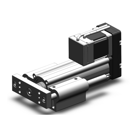
Electric Actuator/Rod Type
25A-LEY 16 100
B C 11 6N
*Refer to the applicable stroke table.
*
When “With lock/motor cover” is selected for the top mounting
and right/left side parallel types, the motor body will stick out of
the end of the body for size 16 with strokes 30 or less. Check
for interference with workpieces before selecting a model.
*Refer to the operation manual for using the products. Please download it via our website, http://www.smcworld.com
S
q w e r t y u i o !0 !1 !2 !3
*Applicable stroke table
*Consult with SMC for non-standard strokes as they are produced as special orders.
qSize
rLead [mm] tStroke [mm]
yMotor option uRod end thread
w
Motor mounting position
eMotor type
[CE-compliant products]
qEMC compliance was tested by
combining the electric actuator
LEY series and the controller LEC
series.
The EMC depends on the configu-
ration of the customer’s control
panel and the relationship with
other electrical equipment and wir-
ing. Therefore conformity to the
EMC directive cannot be certified
for SMC components incorporated
into the customer’s equipment un-
der actual operating conditions.
As a result it is necessary for the
customer to verify conformity to
the EMC directive for the machinery
and equipment as a whole.
wFor the servo motor (24 VDC)
specification, EMC compliance
was tested by installing a noise
filter set (LEC-NFA). Refer to the
WEB catalog for the noise filter
set. Refer to the LECA Operation
Manual for installation.
[UL-compliant products]
When conformity to UL is required,
the electric actuator and controller/
driver should be used with a UL1310
Class 2 power supply.
Caution
Standard
Symbol
Type Size
Compatible
controllers/driver
LEY16 LEY25
LEY32/40
Nil Step motor
(Servo/24 VDC) 
LECP6
LECP1
LECPA
LECPMJ
AServo motor
(24 VDC)   — LECA6
Stroke
[mm]
Model
30 50 100 150 200 250 300 350 400 450 500
Manufacturable
stroke range
[mm]
LEY16 — — — — 10 to 300
LEY25 — — 15 to 400
LEY32/40  20 to 500
30 30
to to
500 500
Nil Female rod end
MMale rod end
(1 rod end nut is included.)
CWith motor cover
WWith lock/motor cover
Symbol
LEY16 LEY25 LEY32/40
A10 12 16
B568
C2.5 3 4
Nil Top mounting
R
Right side parallel
L
Left side parallel
DIn-line
16
25
32
40
Solid state auto switches should be ordered separately.
For details about auto switches, refer to page 164.
Applicable auto switches
D-M9N(V)-900, D-M9P(V)-900, D-M9B(V)-900
D-M9NW(V)-900, D-M9PW(V)-900, D-M9BW(V)-900
Mounting Bracket Part No. for Series 25A-
*1 When ordering foot brackets, order 2 pieces per actuator.
*2 Parts belonging to each bracket are as follows.
Foot, Flange: Body mounting bolt, Double clevis: Clevis pin, Type C retaining ring for axis, Body mounting bolt
Applicable size
Foot *1Flange Double clevis
16 25-LEY-L016 25-LEY-F016 25-LEY-D016
25 25-LEY-L025 25-LEY-F025 25-LEY-D025
32, 40 25-LEY-L032 25-LEY-F032 25-LEY-D032
Surface
treatment RAYDENT®RAYDENT®Coating
(Size 16: Electroless nickel plating)
Step Motor (Servo/24 VDC) Servo Motor (24 VDC)
RoHS
q w
®
25A-P-B-P157-web-CS3e.indd 157 15.2.13 2:06:16 PM
Compatible Controllers/Driver
Type
Step data
input type
Step data
input type
CC-Link
direct
input
type
Programless type Pulse input type
Series LECP6 LECA6 LECPMJ LECP1 LECPA
Features Value (Step data) input
Standard controller CC-Link direct input
Capable of setting up operation
(step data) without using a
PC or teaching box
Operation by
pulse signals
Compatible motor
Step motor
(Servo/24 VDC)
Servo motor
(24 VDC)
Step motor
(Servo/24 VDC)
Maximum number of step data
64 points 64 points 14 points —
Power supply voltage
24 VDC
*Copper and zinc materials are used for the motors, cables, controllers/drivers.
*Specifications and dimensions for the 25A-series are the same as standard products.
158
Electric Actuator/Rod Type Series 25A-LEY
Nil
D
Screw mounting
DIN rail mounting*1
*
Produced upon receipt of order (Robotic cable only)
*1 Mounting bracket is shipped together, (but
not assembled).
*2 For horizontal cantilever mounting with the
rod flange, head flange and ends tapped,
use the actuator within the following stroke
range.
· LEY25: 200 or less
· LEY32/40: 100 or less
*3 For mounting with the double clevis, use the
actuator within the following stroke range.
· LEY16: 100 or less
· LEY25: 200 or less
· LEY32/40: 200 or less
*4 Head flange is not available for the
LEY32/40.
*1 For details about controllers/driver and
compatible motors, refer to the compatible
controllers/driver below.
*2 Only available for the motor type “Step
motor”.
*3 Not applicable to CE.
*4 When pulse signals are open collector, order
the current limit resistor (LEC-PA-R-)
separately.
*1 DIN rail is not included. Order it separately.
iMounting*1oActuator cable type*1!0 Actuator cable length [m]
!1 Controller/Driver type*1!2
I/O cable length [m]
*1
, Communication plug
!3 Controller/Driver mounting
Motor mounting position:
Top/Parallel
*1 The standard cable should be used on fixed
parts. For using on moving parts, select the
robotic cable.
*2 Only available for the motor type “Step
motor”.
*1 When “Without controller/driver” is selected
for controller/driver types, I/O cable cannot
be selected. Refer to the catalog CAT. E102
if I/O cable is required.
*2 When “Pulse input type” is selected for
controller/driver types, pulse input usable
only with differential. Only 1.5 m cables
usable with open collector.
*3 When “CC-Link direct input type” is selected
for controller/driver types, I/O cable is not
included. Only “Nil”, “S” or “T” can be
selected.
Motor mounting position:
In-line
Nil Without controller/driver
6N LECP6/LECA6
(Step data input type)
NPN
6P PNP
1N LECP1*2
(Programless type)
NPN
1P PNP
MJ LECPMJ*2 *3
(CC-Link direct input type)
—
AN LECPA*2 *4
(Pulse input type)
NPN
AP PNP
Symbol
Type
Motor mounting position
Top/Parallel
In-line
Nil
Ends tapped (Standard)
*2 
UBody bottom tapped  
LFoot —
FRod flange*2 
GHead flange*2*4—
DDouble clevis*3—
Nil Without cable
S
Standard cable
*2
R
Robotic cable (Flexible cable)
Nil Without cable
11.5
33
55
88*
A10*
B15*
C20*
Nil
Without cable (Without communication plug connector
*3
)
11.5
33*2
55*2
S
Straight type communication plug connector
*3
T
T-branch type communication plug connector
*3
25A-P-B-P158-web修正-CS3e.indd 158 14.9.11 5:55:39 PM
Air Cylinders
Air Grippers
Directional
Control Valves
Related
Products
Rotary
Actuators
Vacuum
Equipment
Air Preparation
Equipment
Air Filters/Pressure
Control Equipment
Fittings/Flow
Control Equipment
Detection
Switches
Fluid Control
Equipment
Electric
Actuators
Auto
Switches
Clean
Air Filters
A
Series compatible with
secondary batteries
RoHS
AC Servo Motor
How to Order
159
Motor
LEY25, 32
*Applicable stroke table
*Consult with SMC for non-standard strokes as they are produced as special orders.
wSize
*Refer to the table below for details.
yStroke [mm]
*
When “With lock” is selected for the top mounting and right/
left side parallel types, the motor body will stick out of the
end of the body for size 25 with strokes 30 or less. Check
for interference with workpieces before selecting a model.
uMotor option
iRod end thread
e
Motor mounting position
*1 Mounting bracket is shipped together, (but not
assembled).
*2 For horizontal cantilever mounting with the rod
flange, head flange and ends tapped, use the
actuator within the following stroke range.
· LEY25: 200 or less · LEY32: 100 or less
*3 For mounting with the double clevis, use the
actuator within the following stroke range.
· LEY25: 200 or less · LEY32: 200 or less
*4 Rod flange is not available for the LEY25 with
stroke 30 and motor option “With lock”.
*5 Head flange is not available for the LEY32.
*
The values shown in ( ) are the lead for size 32 top
mounting, right/left side parallel types. (Equivalent
lead which includes the pulley ratio [1.25:1])
tLead [mm]
Electric Actuator/Rod Type
25, 32
Size
oMounting*1
rMotor type*1
*1 For motor type “S2” and “S6”, the compatible driver part number suffixes are “S1” and “S5”
respectively.
*2 For details about the driver, refer to the WEB catalog.
Standard
Symbol
Type Output [W] Actuator size
Compatible drivers
*2
S2 AC servo motor
(Incremental encoder) 100 25 LECSA-S1
S3 AC servo motor
(Incremental encoder) 200 32 LECSA-S3
S6 AC servo motor
(Absolute encoder) 100 25
LECSB-S5
LECSC-S5
LECSS-S5
S7 AC servo motor
(Absolute encoder) 200 32
LECSB-S7
LECSC-S7
LECSS-S7
Symbol
Type
Motor mounting position
Top/Parallel
In-line
Nil
Ends tapped (Standard)
*2 
UBody bottom tapped  
LFoot —
FRod flange*2*4
GHead flange*2*5—
DDouble clevis*3—
Symbol
LEY25 LEY32*
A12 16 (20)
B6 8 (10)
C3 4 (5)
Nil Top mounting
R
Right side parallel
LLeft side parallel
DIn-line
Nil Female rod end
MMale rod end
(1 rod end nut is included.)
Nil Without option
BWith lock*
30 30
to to
500 500
Stroke
[mm]
Model 30 50 100 150 200 250 300 350 400 450 500
Manufacturable
stroke range [mm]
LEY25 — — 15 to 400
LEY32 20 to 500
25
32
Solid state auto switches should be ordered separately.
For details about auto switches, refer to page 164.
Applicable auto switches
D-M9N(V)-900, D-M9P(V)-900, D-M9B(V)-900
D-M9NW(V)-900, D-M9PW(V)-900, D-M9BW(V)-900
Mounting Bracket Part No. for Series 25A-
*1 When ordering foot brackets, order 2 pieces per actuator.
*2 Parts belonging to each bracket are as follows.
Foot, Flange: Body mounting bolt, Double clevis: Clevis pin, Type C retaining ring for axis,
Body mounting bolt
Applicable size
Foot*1Flange Double clevis
25 25-LEY-L025 25-LEY-F025 25-LEY-D025
32 25-LEY-L032 25-LEY-F032 25-LEY-D032
Surface
treatment RAYDENT®RAYDENT®Coating
(Size 16: Electroless nickel plating)
Series
25A-LEY
25A-LEY 25 100
BH 2 A1S
w e r tq y u i o !0 !1 !2 !3
S2
qAccuracy
Nil
Basic type
H
High precision type
25A-P-B-P159-webA-CS3e.indd 159 15.2.13 2:05:19 PM
A
*Specifications and dimensions for the 25A-series are the same as standard products.
160
Electric Actuator/Rod Type Series 25A-LEY
Motor mounting position:
Top/Parallel
Motor mounting position:
In-line
*The motor and encoder cables are included.
(The lock cable is also included when the
motor with lock option is selected.)
*Standard cable entry direction is
· Top/Parallel: (A) Axis side
· In-line: (B) Counter axis side
!0 Cable type*
*The length of the encoder, motor and lock
cables are the same.
!1 Cable length*[m]
Compatible Drivers
!2 Driver type*
*When the driver type is selected, the cable is
included. Select cable type and cable length.
Example)
S2S2:
Standard cable (2 m) + Driver (LECSS2)
S2 :
Standard cable (2 m)
Nil : Without cable and driver
25, 32
Size
Compatible drivers
Power supply voltage (V)
Nil Without driver —
A1 LECSA1-S100 to 120
A2 LECSA2-S200 to 230
B1 LECSB1-S100 to 120
B2 LECSB2-S200 to 230
C1 LECSC1-S100 to 120
C2 LECSC2-S200 to 230
S1 LECSS1-S100 to 120
S2 LECSS2-S200 to 230
Driver type
Pulse input type/
Positioning type
Pulse input type CC-Link direct
input type
SSCNET#type
Series LECSA LECSB LECSC LECSS
Number of point tables
Up to 7 —
Up to 255 (2 stations occupied)
—
Pulse input   — —
Applicable network — — CC-Link SSCNET3
Control encoder Incremental
17-bit encoder
Absolute
18-bit encoder
Absolute
18-bit encoder
Absolute
18-bit encoder
Communication function
USB communication
USB communication, RS422 communication USB communication, RS422 communication
USB communication
Power supply voltage (V)
100 to 120 VAC (50/60 Hz)
200 to 230 VAC (50/60 Hz)
*Copper and zinc materials are used for the motors, cables, controllers/drivers.
Nil Without cable
22
55
A10
Nil Without cable
SStandard cable
RRobotic cable (Flexible cable)
!3 I/O cable length [m]*
Nil Without cable
HWithout cable (Connector only)
11.5
*When “Without driver” is selected for driver
type, only “Nil: Without cable” can be selected.
Refer to the WEB catalog if I/O cable is
required.
25A-P-B-P160-web修正-CS3e.indd 160 14.10.9 9:08:32 PM
Air Cylinders
Air Grippers
Directional
Control Valves
Related
Products
Rotary
Actuators
Vacuum
Equipment
Air Preparation
Equipment
Air Filters/Pressure
Control Equipment
Fittings/Flow
Control Equipment
Detection
Switches
Fluid Control
Equipment
Electric
Actuators
Auto
Switches
Clean
Air Filters
A

This manual suits for next models

4

Other SMC Networks Controllers manuals

SMC Networks ASBL Series User manual

SMC Networks

SMC Networks ASBL Series User manual

SMC Networks ITV10*0-PR*-Q Series Manual

SMC Networks

SMC Networks ITV10*0-PR*-Q Series Manual

SMC Networks LEH Series User manual

SMC Networks

SMC Networks LEH Series User manual

SMC Networks ClimateWorx FieldServer ProtoNode FPC-N34 User guide

SMC Networks

SMC Networks ClimateWorx FieldServer ProtoNode FPC-N34 User guide

SMC Networks LECP2 Series User manual

SMC Networks

SMC Networks LECP2 Series User manual

SMC Networks CHSD Series User manual

SMC Networks

SMC Networks CHSD Series User manual

SMC Networks LECP6 Series User manual

SMC Networks

SMC Networks LECP6 Series User manual

SMC Networks THERMO-CON HEC001 Series Use and care manual

SMC Networks

SMC Networks THERMO-CON HEC001 Series Use and care manual

SMC Networks AS 0 2F Series User manual

SMC Networks

SMC Networks AS 0 2F Series User manual

SMC Networks ITVX Series User manual

SMC Networks

SMC Networks ITVX Series User manual

SMC Networks LEYG User manual

SMC Networks

SMC Networks LEYG User manual

SMC Networks ITV1000 series User manual

SMC Networks

SMC Networks ITV1000 series User manual

SMC Networks CRB2BW40 Series User manual

SMC Networks

SMC Networks CRB2BW40 Series User manual

SMC Networks IZN10 Series User manual

SMC Networks

SMC Networks IZN10 Series User manual

SMC Networks DAS User manual

SMC Networks

SMC Networks DAS User manual

SMC Networks VBA10A User manual

SMC Networks

SMC Networks VBA10A User manual

SMC Networks EX600-SPN1 Instruction Manual

SMC Networks

SMC Networks EX600-SPN1 Instruction Manual

SMC Networks IR2000-A Series User manual

SMC Networks

SMC Networks IR2000-A Series User manual

SMC Networks VBA10A-02-X3239 User manual

SMC Networks

SMC Networks VBA10A-02-X3239 User manual

SMC Networks ITV1000-DE Series User manual

SMC Networks

SMC Networks ITV1000-DE Series User manual

SMC Networks LEC 6 Series User manual

SMC Networks

SMC Networks LEC 6 Series User manual

SMC Networks LECP1 Series User manual

SMC Networks

SMC Networks LECP1 Series User manual

SMC Networks JXCEH User manual

SMC Networks

SMC Networks JXCEH User manual

SMC Networks ITV1000 series User manual

SMC Networks

SMC Networks ITV1000 series User manual

Popular Controllers manuals by other brands

Espa PRESSDRIVE instruction manual

Espa

Espa PRESSDRIVE instruction manual

VOLTIMA SCD 12 Installation and operating manual

VOLTIMA

VOLTIMA SCD 12 Installation and operating manual

Sonnet TEMPO SATA PRO EXPRESSCARD/34 user guide

Sonnet

Sonnet TEMPO SATA PRO EXPRESSCARD/34 user guide

Wilkerson CB6B Installation & service instructions

Wilkerson

Wilkerson CB6B Installation & service instructions

hager WUT09 manual

hager

hager WUT09 manual

Loctite 97152 operating manual

Loctite

Loctite 97152 operating manual

AirCom DB26 operating manual

AirCom

AirCom DB26 operating manual

Carel pCO user guide

Carel

Carel pCO user guide

Omron CK3E Series Connection guide

Omron

Omron CK3E Series Connection guide

Emerson FISHER LR128 Series installation guide

Emerson

Emerson FISHER LR128 Series installation guide

QED Micropurge MP10 instruction manual

QED

QED Micropurge MP10 instruction manual

dixell XWA11V operating instructions

dixell

dixell XWA11V operating instructions

FUTABA PK-FSM-2.4G instruction manual

FUTABA

FUTABA PK-FSM-2.4G instruction manual

iSMA B-FCU user manual

iSMA

iSMA B-FCU user manual

Emerson Fisher 92C instruction manual

Emerson

Emerson Fisher 92C instruction manual

AL-KO ATC operating instructions

AL-KO

AL-KO ATC operating instructions

ARIS SCU5 user manual

ARIS

ARIS SCU5 user manual

GHM Greisinger GRA 0420 WK manual

GHM Greisinger

GHM Greisinger GRA 0420 WK manual

manuals.online logo
manuals.online logoBrands
  • About & Mission
  • Contact us
  • Privacy Policy
  • Terms and Conditions

Copyright 2025 Manuals.Online. All Rights Reserved.