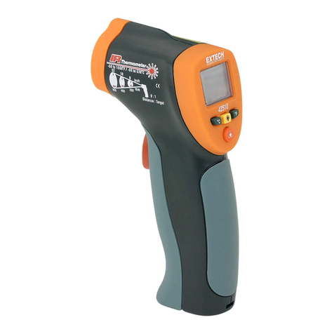
BST BT-64 User manual

BT-64
MULTIFUNCTION IR THERMOMETER
OPERATION MANUAL
1. SAFETY RULES
To ensure that the meter is used safely, follow all safety and operating instructions in
this operation manual. If the meter is not used as described in this operation manual,
the safety features of this meter might be impaired.
Do not look directly into the laser beam when the device is in use–permanent eye
damage may result.
Use extreme caution when operating the laser.
Never point the device towards anyone’s eyes.
Keep out of reach of children.
2. INTERNATIONAL SYMBOLS
3. SPECIFICATIONS
Important information
see manual
Laser device. Avoid towards
anyone’s eyes
Item Non-contact Infrared Scan
Function
Thermocouple Probe Scan function
(K type; probe not included.)
-60 to +1000°C
(-76 to +1832°F)
-64 to +1400°C
(-83.2 to +2552°F)
Measurement
Range
0 to +50°C (32 to 122°F)
±1% of reading or 1°C (1.8°F)
whichever is greater (Test under
Tamb.=23±6°C)
0.95 default – adjustable 0.1 to 1 step .01
0.1°C/0.1°F at -83.2 to +999.9(°C/°F), otherwise 1°C/1°F
1sec
1~99%, accuracy: ±3% from 20~80%, otherwise ±5%
Operating Range
Accuracy (Tamb=
23±3°C)
±1.0°C (1.8°F)
Emissivity Range
Resolution
Relative Humidity
(Tamb=23±5degC
Response Time
(90%)
30:1 (90% energy covered)
Distance: Spot
Internal Memory Detailed 50 Memories with Temperature & Emissivity
-20 ~ +65°C, accuracy: ±2.5°C
4. THERMOMETER DESCRIPTIONS
5. OPERATION
WARNING
The measurement range is for thermometers only. Users should choose proper probe
types for dierent kinds of applications. Please make sure the target to be measured
will not exceed the temperature range of the probe to avoid permanent damage to the
thermocouple probe.
Caution: To avoid electric shock and thermometer damage, do not measure the live
circuit with the thermocouple probe voltage exceeding 24V AC RMS or 60V DC.
EMC/RFI: Readings may be aected if the unit is operated within radiofrequency
electromagnetic eld strength of approximately 3 volts per meter, but the instrument's
performance will not be permanently aected.
5.1 Function Selection
Press Mode Key (4) for scrolling display functions as follows:
Display Function
THB (thermal bridge detection) is the default mode.
Here will show the emissivity data. (The default emissivity is
0.95.)
Press Mode key (4) for the Maximum (MAX), Minimum (MIN),
Dierent between MAX and MIN (DIF) and Average (AVG)
modes. During the measurement, the special modes reading
will be displayed beside the mode icon.
** The Thermometer will automatically shut o if left idle for more than 60sec., unless in PRB
mode. (In PRB mode, it will shut o if left idle for more than 12 minutes.)
1)
2)
3)
•
•
•
•
•
Accuracy (Tobj=15-
35°C, Tamb=25°C)
Tobj=-60~0: ±(2+0.05/°C)°C,
Tobj=0~1000: ±2% of reading
or 2°C (4°F) whichever is
greater
Dry bulb
temperature
Wet bulb
temperature -20 ~ +65°C, accuracy: ±2.5°C
Dew Point
Temperature (DPT)
-50 ~ +50°C, accuracy: ±2.5°C from 20~30%RH; ±2°C from
31~40%RH; ±1.5°C from 41~95 %RH
Battery Life
(Alkaline)
Typical 8 hours, minimum 7 hours continuous use (Alkaline battery,
with laser and backlight)
Typical 32 hours, minimum 30 hours continuous use (Alkaline
battery, with backlight but without laser)
Dimensions 53 x 124 x 171 mm (2.1 x 4.9 x 6.7 inch)
Weight ~240 g (8.5 oz) including batteries (AAA*2pcs)
(DPT) Display (THB) Display
IRT (infrared temperature) – Tamb (temperature
ambient) > 6.5°C: icon displays “red side
ashing”, the bar shows RED color, and “Hi” is
beside the THB mode icon.
(a)
IRT - Tamb < -6.5°C: icon displays “blue
side ashing”, the bar shows BLUE color, and
“Lo” is beside the THB mode icon.
(b)
IRT – Tamb > 5.75°C or < -5.75°C: The buzzer
and optional vibration functions will start
activating at the same time.
(c)
According to the following value, “CHK” (check)
is displayed beside the THB mode icon and
please continue to observe.
(d)
4.25°C < IRT - Tamb < 6.5°C: the bar shows RED color; -3.5°C
≦IRT - Tamb < 4.25°C: the bar shows YELLOW color; -6.5°C <
IRT - Tamb < -3.5°C: the bar shows BLUE color.
Press Mode key (4), then press Up key (2) or Down key (3) to
set the emissivity, then press Mode key (4) to conrm it. The
emissivity can be changed from 0.10 (10E) to 1 (100E).
Press Up key (2) or Down key (3) to change the High Alarm
(HAL) or Lo Alarm (LAL), then press Meas. key (6) to conrm it.
When the reading is outside the High Alarm (HAL) or Lo Alarm
(LAL) limit. The High or Low icon will ash and you will hear a
beep sound.
Connect the thermocouple with Thermocouple Socket (10) and
put the probe in/on the target, the thermometer will display the
temperature automatically without pressing any button. To see
the minimum or maximum data during the probe measurement,
please hold down the Up key (2 or Down key (3).
After measure high temp, the probe may remain HOT for a
while.
Press Mode key (4) for the RH% (relative
humidity) mode, then press Up key (2) for DBT
(dry bulb temp), WBT (wet bulb temp.) modes.
During the measurement, the special modes
reading will be displayed beside the mode
icon.
(a) 60% < RH ≦ 75%: The screen displays icon.
(b) 75% < RH ≦ 90%: The screen displays icon.
(c) RH > 90%: The screen displays icon.
After taking the temperature, press Mode key (4) for the Memory
(M00), then press Meas. key (6) to save the measurement.
Under the Memory (M00), press Up key (2) or Down key (3) key
to display the record up to 50 sets. In “Memory” mode, press and
hold the “Up” key, then press the “Down” key for 2 seconds to
clear the records.
Press Mode key (4) for DPT (dew point
temperature) modes. During the measurement,
the special modes reading will be displayed
beside the mode icon.
(a) IRT (infrared temperature) - DPT (dew point temperature)
> 1.9°C: The bar shows YELLOW color.
(b) 1.1°C < IRT - DPT ≦ 1.9°C: The bar shows Blue color and
displays icon.
(c) -0.5°C < IRT - DPT ≦1.1°C: The bar shows Blue color and
displays icon.
(d) IRT - DPT ≦-0.5°C: The bar shows Blue color and
displays icon.
In (b), (c) and (d) cases, the icon , , is the indication
for the risk of condensation as well as mold warning, the buzzer
and optional vibration functions are activated at the same time.
Class Illa Laser
Laser
Note: Not recommend using external K-type thermocouple for long time measurement
above 1000°C (1832°F)

5.2 Other Function Selection
In all modes:
In MAX, MIN mode:
Hold the Meas. key (6)
In all modes: First, hold
the Meas. key (6)
Press Up key (2) for LOCK mode ON/OFF. The lock mode is
particularly useful for continuous monitoring of temperatures
for up to 60 minutes.
Press Down key (3) for °C or °F transferred.
The Bar display indicates the
measuring temperature. The
bar shows RED color when the
reading is close to maximum
value, and shows BLUE when
close to minimum. While the
temperature is between the
maximum and minimum, the
bar will display in YELLOW.
LCD Backlight: always on.
Press Down key (3) for laser function ON/OFF.
5.3 Temperature Measurement
Simply aim the thermometer at the measure target with Lens (7) and press Meas. key (6) to
display the surface temperature. The Distance:Spot is 30:1. Please make sure the target area
is within the eld of view.
5.4 LCD Error Messages
The Thermometer incorporates visual diagnostic messages as follows:
‘Hi’ or ’Low’ is displayed when the temperature being
measured is outside of the settings of HAL and LAL.
‘Er2’ is displayed when the thermometer is exposed to rapid
changes in the ambient temperature. ‘Er3’ is
displayed when the ambient temperature exceeds the range
of 0°C (32°F) ~ 50°C (122°F). The thermometer
should be allowed plenty of time (minimum 30 minutes) to
stabilize to the working/room temperature.
Error 5~9, for all other error messages it is necessary to
reset the thermometer. To reset it, turn the instrument o,
remove the battery and wait for a minimum of one minute,
reinsert the battery and turn on. If the error message
remains please contact the Service Department for further
assistance.
‘Hi’ or ’Lo’ is displayed when the temperature being
measured is outside of the measurement range.
6. MAINTENANCE
CAUTION
BEFORE ATTEMPTING BATTERY REMOVAL OR REPLACEMENT, DISCONNECT
EXTERNAL PROBES FROM AN ARTICLE UNDER TEST.
6.1 Fitting and replacing the battery
The Thermometer incorporates visual low battery indication as follows:
‘Battery OK’: measurements are possible
‘Battery Low’: battery needs to be replaced, measurements are still
possible
‘Battery Exhausted’: measurements are not possible
When the ‘Low Battery’ icon indicates the battery is low, the battery should be replaced
immediately with AAA, 1.5V batteries. Please note: It is essential to turn the instrument o
before replacing the battery; otherwise, the Thermometer may malfunction.
Dispose of used battery promptly and keep away from children.
If the device is not used for a long time, turn the power o, remove and store the batteries in
a cool, dry place.
1.
2.
3.
6.2 Storage & Cleaning
It should be stored at room temperature. The sensor lens is the most delicate part of the
thermometer. The lens should be kept clean at all times, care should be taken when cleaning the
lens using only a soft cloth or cotton swab with water or medical alcohol, allowing the lens to fully
drybefore using the thermometer. Do not submerge any part of the thermometer.
7. ACCESSORIES
The accessories contained inside the packaging are the following:
1.5V AAA battery x 2
English instruction manual
••
8. SERVICE
8.1 Limited Warranty Conditions
This Thermometer is guaranteed against any material fault or manufacturer’s defect
under the general conditions of sale. During the warranty period (12 months from
shipment date), faulty parts may be replaced, with the manufacturer reserving the
right to repair or replace the product.
In returning the Thermometer to the after-sales service or a regional branch, the
customer pays the inward outward transporter. The delivery must be agreed upon in
advance with the consignee.
For delivery, indicate the reasons for returning it through an enclosed note as simple
as possible. Use only the original packing.
Any damage caused by shipment using NOT the original packaging will be charged
in any case to the consignor.
The manufacturer will not be responsible for any damage to persons or thing
The warranty does not apply to the following cases:
Accessories and batteries are not included in the warranty.
Unsuitable use of the Thermometer or combining the latter with incompatible
Thermometer or accessories.
Repairs resulting from incorrect shipping.
•
•
•Repairs resulting from servicing carried out by a person not approved by the
company.
•
Modications to the Thermometer without explicit authorization from our technical
department.
•
Inappropriate applications are not provided for by the denition of the
Thermometer or by the instruction manual.
•
The contents of this manual may not be reproduced in any form whatsoever without
the manufacturer’s authorization.
8.2 Before calling Service
If the Thermometer should not work correctly, before contacting the DEALER OR
THE SERVICE CENTRE, check the battery condition, the test leads, etc., Change
them if necessary.
If the Thermometer still does not work, check if your operating procedure agrees with
the description in this manual.
FOR TECHNICAL ASSISTANCE,
PLEASE CONTACT:
In all modes:
Remarks: Due to our policy of continual product development, we reserve
the right to amend the specications of the mentioned products without
notice.
BT-64
REV1.0/MAY22
Other BST Thermometer manuals
Popular Thermometer manuals by other brands

180 INNOVATIONS
180 INNOVATIONS KI-8130 instruction manual
Medisana
Medisana 77055 instruction manual
Zico
Zico ZI-9613 operating instructions
Hanna Instruments
Hanna Instruments Foodcare HI 93501 instruction manual

ThermoWorks
ThermoWorks ChefAlarm TX-1100-OR instructions

Braun
Braun ThermoScan IRT 4520 user manual

