BTE SUPER FLYIN' KING Instruction Manual

BUILDING INSTRUCTIONS FOR THE BTE
Written by Bruce Tharpe June 2013
Wingspan: 132 inches
Wing Area: 3380 square inches
Length: 96 inches
Weight: 36 pounds (approximate)
Engine Range: 60cc - 80cc Gas
Manufactured by
BRUCE THARPE ENGINEERING
8622 E EVANS CREEK ROAD, ROGUE RIVER, OR 97537
phone: 541-582-1708
orders: 800-557-4470
website: www.btemodels.com
e-mail: bruce@btemodels.com

! " " # $
%% " %
% "
TABLE OF CONTENTS
!"#$!%&&
'
(! !"#$!%&&
)
!"*! !$%%$ !
+
!"$,%
-
!. !"#$!%
/
!.(! !"#$!%
01
$%!$!2%$#
0'
$ %34%5$4 !4$!222
0)
%$"2( !
0+
%$"$,%
0-
%$"&&
06
,! !". !"
07
!..%$"
'1
!"! !$%%$ !
'0
$2$!2(!%%!$" !$%%$ !
''
$%$(
'8
#&%".#
'-
%9!" #
'6
# !$%$((
'/
(,#%#$%
'7
&5%!2$ !"
)1

Left Outer Wing Panel, Inboard End -
Plywood
W-
2 rib is set at the proper dihedral angle using
the 5/32" ply shear web E as a
guide. The angle
is 2°; move the web all along the rib to be sure it
is straight along its entire length, front to back.
Left Outer Wing Panel with all spars, sub LE, and servo lead tube
in place. Shear webs have yet to be added.
!" # $ # !
$ ! # % # & ' # %
# % ! # # " !!# !
( ! !! # ! )
# ! %
!! * + , !"
' !
- %. # !/ 0
!1 !# % !!!" !/
" ' !/ # !
# !1 !# !/ " "
% ! ,
- # # %
# # ! ! 2 # #
$ ! ! !# # !/
( ! & 3 & . & 3 3 4 ! ! # !
5 ! / $ ! # !6 !! # # !7" # !/ "
!!" # 5 " / " / # " " !!/ $ ! !
- 8 9 : 2 1 : 2 ; 6
" # # !!
/ #
/ / ! "
! * 2 /
! !
# !/
$ / / % " $
# ! " ! $ !!
" " < - !1 " $ /
%# !=!!/ " !!!!" #
!# !/ > < -
1 " # ! # ! = " # !%
!? @3 & A + # # ! 1 !" / $ !
" # %" " !
9 # # # # !%"
W-2 and
one W
-
4
Cut at the dotted lines to connect
the drill holes, front and rear

Center Wing Panel - Notice the screws holding
the bottom main spar to the table. The front
screw needs to be removed before the shear web
can be added. Note the grain of every shear web
must be vertical!
W-1 Wing Ribs -
I used a scrap stick to hold the
ends of the W-
1 ribs, but found out later it would
have been smarter to use
a sheet of 3/32" balsa,
maybe one or two inches wide. Use only a few
spots of glue so it can be removed later. Also
notice in the photo the position of the aileron and
flap servo lead tubes. I moved the aileron tubes
forward in the production models to
make room
for the large flap servos used in the prototype.
!" #
$ % &' (' )
"% &* +
,
-
# ( (. ('
/0
#
1 . (% . (2
,
1 . (* . (' . ('
3 4 5
6 % &% 7 #
. ('
1 . . (' !
, 8 9
,
1 # : ; < ; < 8 =
$ =
, 2 &2 '
. (%
: (
> ,

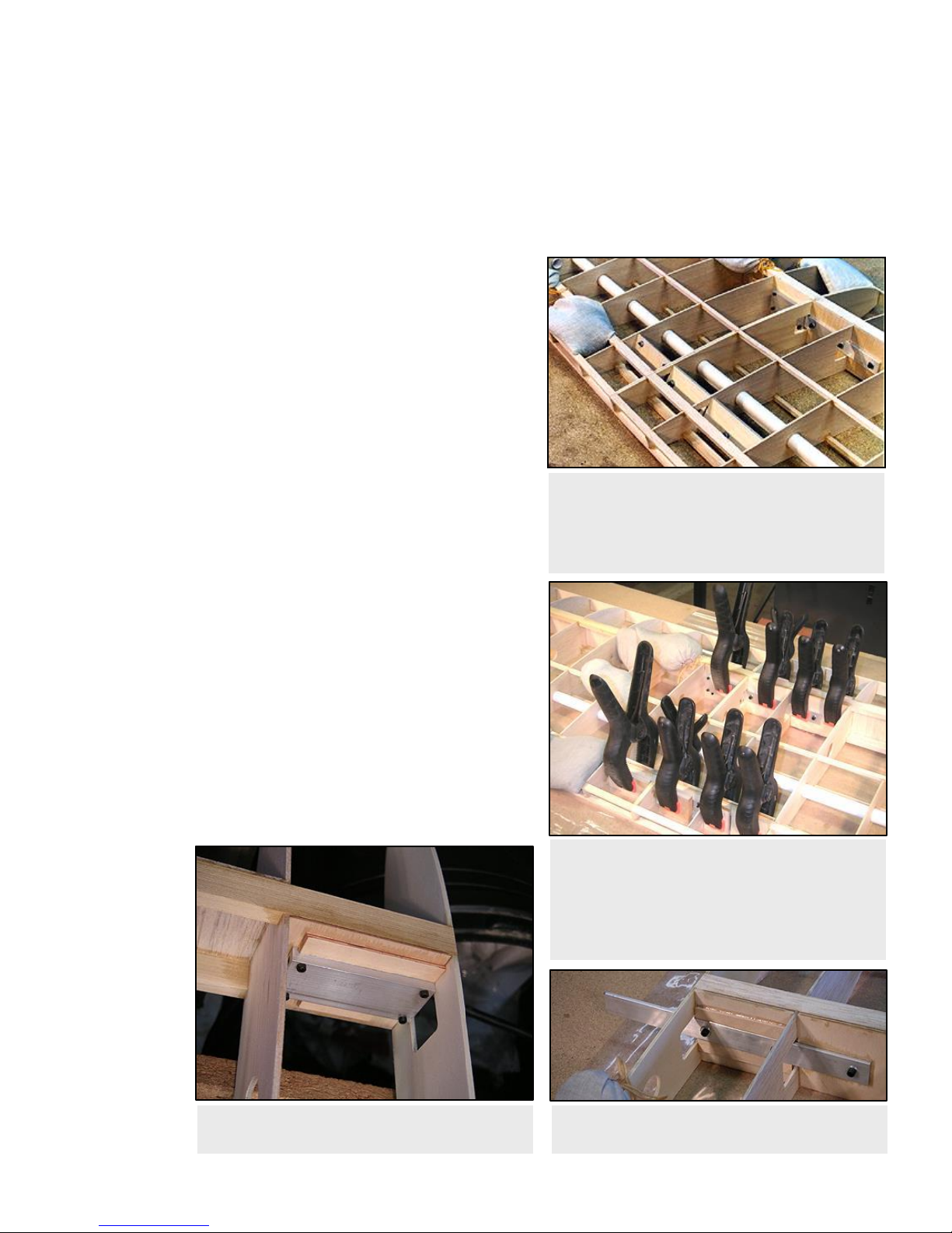
Top: Front Joiner Assembly. Bottom: Rear
Joiner Assembly - At this point, the joiners have
been fastened to the center section shear webs.
Notice the "open" side of the C-channel is
positioned against the face of the plywood web.
With the center panel flat on the table and the
assemblies clamped in place, make certain the
joiners are parallel to each other and the table.
1 WING JOINER INSTALLATION >
Prepare the wing joiners exactly as described in the Sig directions. Okay, maybe one exception: If you don't
have numbered drill bits (like me), you can use a 7/64" drill for the 4-40 bolts (the mounting bolts, not the set screws)
and a 9/64" drill for the 6-32 bolts. Slide the joiners into the C-channels, tighten the set screws, and set aside.
Use the Shear Web Identification drawings (on the plans) to locate the internal shear webs A, B, and C. Trial
fit these internal webs between the main spars. Trim as necessary; try for a snug fit.
Trial fit the external shear webs D, E, and F against the aft faces of the main spar. Actually, webs E and F
should fit perfectly because you used these earlier to position the W-2 ribs. Hold the webs in place and mark the
spar locations using a pencil from the front side. Now you can glue the internal webs to the external webs using the
pencil lines for proper alignment. Web A glues to web D, B glues to E, and C glues to F.
Trial fit the three rear shear webs G, H, and J against the rear spars; trim to fit as necessary.
Working with the center wing panel only, position the
shear webs for the C-channels, front and rear. No glue yet! You
might have to use tape to hold the rear web in place against the
rear spars. Now position your joiner assemblies on the webs. I
positioned my set screws heads-down, so they can be tightened
through holes in the bottom of the wing. They may be positioned
on top, if you prefer. Visually inspect the aluminum joiners to be
certain they are parallel, then mark the webs (mechanical pencil)
through the four mounting holes in each C-channel.
Remove the joiner assemblies and the webs from the
center panel, then carefully drill the webs (3/32” drill bit) at the
marks. Bolt the C-channels to the webs using the high-quality hardware supplied with the kit:
Each Front C-channel: Four 4-40 x 1" Socket-Head Bolts, #4 Washers, and 4-40 Hex Nuts
Each Rear C-channel: Four 4-40 x 3/4" Socket-Head Bolts, #4 Washers, and 4-40 Hex Nuts
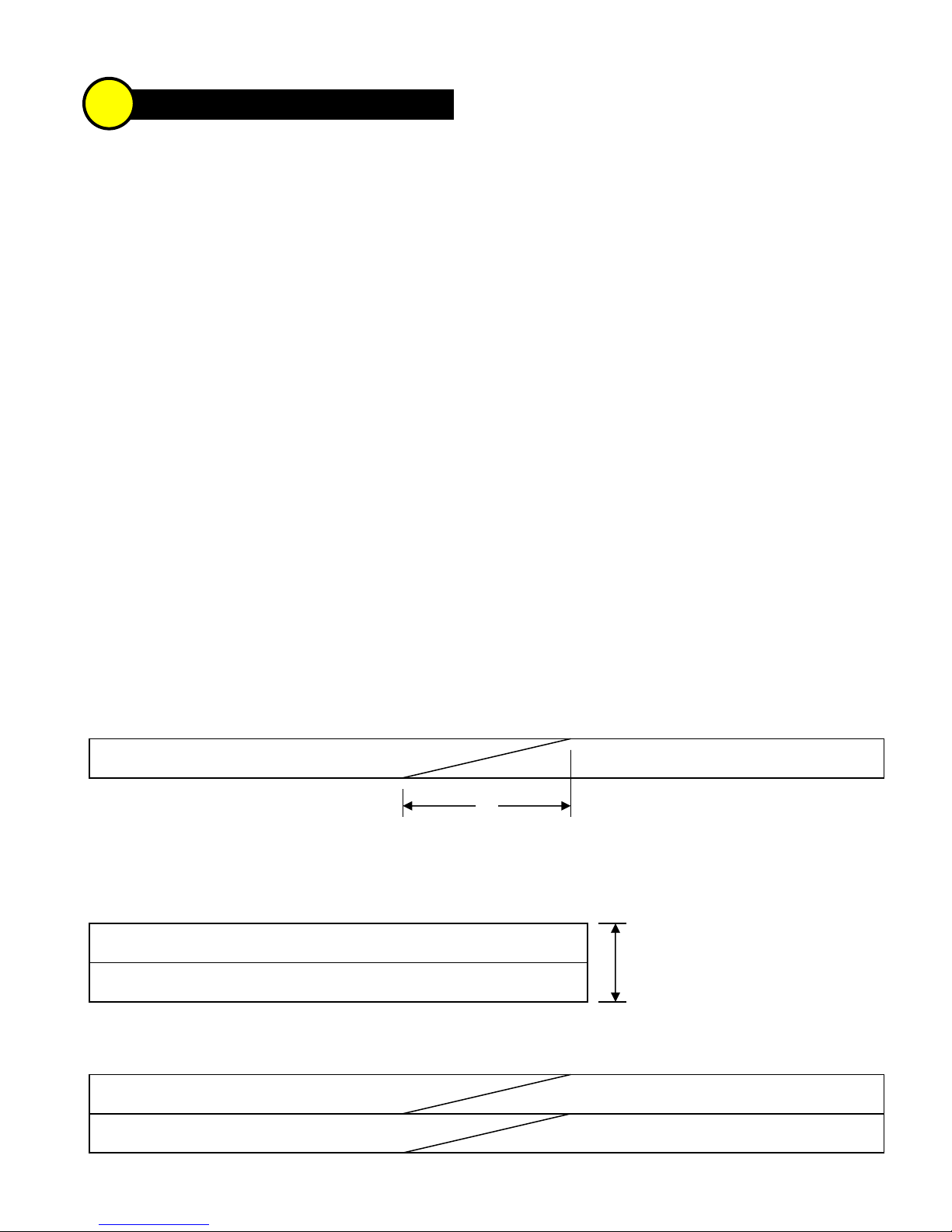
You will have to notch the rear spars to clear the
mounting hardware used on the rear joiner. Try to make the
notches as small as possible in order to maintain spar strength.
Temporarily fit the shear webs in the outer wing panel,
front and rear. Again, you may have to tape the rear webs to
the rear spars.
Position the webs with the joiner assemblies in the
center section, again without glue. With the center section firm
on your table (I used beanbags filled with lead shot), slide the
outer panel into position. Prop up the wingtip end of the outer
panel 1-1/4" off the table for proper dihedral. The W-2 ribs
should fit against each other pretty well at this point, and the
aluminum joiners should be resting against the faces of the plywood webs in the outer panel. Carefully mark the
webs through the joiner mounting holes.
3
PAGE 4

Both Joiner Assemblies are now bolted in place,
but the webs have not been glued yet. The front
joiner/web assembly is still in position, but the
rear joiner/web assembly has been pulled away
from the spars so that glue can be applied.
Joiner/Web Assemblies are glued and clamped
firmly. Temporary pieces of plywood are used on
the opposite side of the spars for clamping
purposes. Use epoxy, but keep it away from the
actual wing joint between the two lite-ply W-2
wing ribs.
Plywood Scraps are glued above and below the
C-channels for extra strength. Rear channel too!
Plywood Scraps are glued above and below the
joiners for extra strength. Rear joiners too!
WING JOINER INSTALLATION, CONTINUED...
Remove the outer panel and the webs. Drill at the marks (9/64’), put the webs back in the outer panel, then
slide the outer panel into its final position against the center panel. Bolt the joiners to the webs with this hardware:
Each Front Joiner - Three 6-32 x 1" Socket-Head Bolts, Six #6 Washers, and Three 6-32 Hex Nuts
Each Rear Joiner - Three 6-32 x 3/4" Socket-Head Bolts, Six #6 Washers, and Three 6-32 Hex Nuts
Notice I used a washer under the bolt heads to keep the bolts
from digging into the aluminum.
Now the webs are ready to be glued into place.
Without disturbing the position of the wing panels, work the
webs away from their spars. Apply slow-drying epoxy to both
the webs and the spars, reposition the webs, and clamp them in
place. CAUTION! Be careful not to get any glue in the joint
between the wing panels. The whole idea here is for the wing
panels to come apart!
When dry, remove the wing from the board, loosen the
set screws and separate the wing panels. Mix another batch of
epoxy and use a disposable brush to coat the area thoroughly
between the top and bottom spars, including the internal webs,
spars, and mounting hardware. This is not the place to be stingy
with the epoxy!
For extra strength, glue scrap pieces of hard plywood
(3/32 or 1/8) along the top and bottom edges of all the joiners and
C-channels. This is a very important step because there will be a
lot of stress and pressure on the channels trying to twist them out
of position, especially when flying aerobatics.
Having fun? Good! Repeat these steps for the other
side.... -SFK
PAGE 5

1 WING SUBASSEMBLIES >
Time for a bit of tedium here. Once these time-consuming tasks are done, you will be ready to take on the
final assembly of the wing panels with minimal delay. Let's roll...
Sort the Balsa Sheets -Go through the 3/32" x 3" x 36" sheets provided and sort them as follows:
16 Leading Edge Sheeting - Look for medium weight, long grained pieces that bend uniformly
8 Center/Wing Joint Sheeting - This can be slightly heavier than the leading edge sheeting
8 Trailing Edge Sheeting - Use the heaviest, stiffest sheets here.
12 Aileron/Flap Sheeting - Light to medium wood is okay, you want to keep the control surfaces light
2 Leftover - You'll need some for the Fuselage, but mainly these are extras (you know, just in case)
Flap Sheeting - Select six 3/32" x 3" sheets to use as flap sheeting. Cut all six sheets to a length of 24" and
save the 12" cutoffs for later. Take four of the 24" sheets and slice them down the middle, lengthwise. Now you
should have eight pieces, 1-1/2" x 24". These will be used as the top and bottom sheeting for the flaps (two on top,
two on bottom of each flap). If the edges are slightly bowed, you can trim them again to a width of 1-3/8"; it's not
critical. Take the two remaining sheets and slice each slightly off-center so that you end up with a piece that's 1-5/8"
and another that's 1-3/8". The 1-5/8" x 24" strips are for the front face of the flaps and the 1-3/8" x 24" strips are for
the rear face of the wing. Mark the sheeting as you go so you'll remember their uses later on.
Aileron sheeting - Select another six sheets and slice four of them in half along their full length. These eight
1-1/2" x 36" pieces will be used for aileron sheeting. Cut the remaining two sheets to 1-5/8" and 1-3/8". Like the
flaps, the 1-5/8" x 36" strips are for the front face of the ailerons and the 1-3/8" x 36" strips are for the wing rear face.
Trailing Edge Sheeting - These need to be trimmed slightly. Trim four sheets to a width of 2-3/4"; these will
be used on the top surface of the wing panels. Trim four pieces to 2-1/2" to use on the wing bottom. The top and
bottom sheets for the center panel will need to be spliced. Make the splices in all sheeting at least 8" long.
Leading Edge Sheeting, Outer Panels - Make four sets of LE sheeting. Each set is made from two pieces
of balsa, edge glued along their entire length. The tricky part here is that the final width of the LE sheet MUST be as
close to 6" as possible, which means there is very little room for trimming. Fortunately, most sheets are slightly
oversize, so it may be possible to trim them if necessary. Try to find sheets that match without trimming.
Leading Edge Sheeting, Center Panel - Make two sets. This one is the trickiest. If I can do it, so can you.
Start with the splices, then do the long edge joint. Again, keep the overall width as close to 6" as possible.
4
PAGE 6
8"
3/32" x 2-3/4" x 36" Balsa Top TE Sheeting
Not to Scale
3/32" x 3" x 36" Balsa - 2 Sheets Edge Glued
Leading Edge Sheeting, Outer Panels - Make 4
6" Preferred, 5-7/8" Minimum
Leading Edge Sheeting, Center Panel - Make 2

18"
12"
Center Sheeting - Make 2
4"
12"
Servo Mount - Lite-ply with bass rails.
This servo is a Hitec HS-700BB. It's
physically a very large servo with lots of
torque and a surprisingly low price.
Note the heavy-duty Du-Bro servo arm.
WING SUBASSEMBLIES, CONTINUED...
Center Sheeting - You'll need four 36" sheets to make
two center sheets (one top, one bottom) for the wing center panel.
If you look ahead, you will see that I got a little fancy with my
center and wing joint sheeting, adding curved edges to the
corners. This is totally unnecessary; I just think it looks cool and
may help avoid those nagging little covering wrinkles that often
occur where sheeting meets at 90°. If you want to try this on
yours, plan ahead now and use extra balsa as necessary. This is
where those leftover sheets may come in handy.
Wing Joint Sheeting - Make eight sets of these, all identical.
Again, you may want to add extra wood for trimming curved corners later.
Center TE Sheeting - (no diagram) This is to sheet the small wing section between
the flaps in the center wing panel. The final piece for the top should be 4-1/2" x 10-1/8" and
the piece for the bottom should be 6" x 10-1/8".
Wing Filler -(no diagram) Six pieces of 1/2" x 2-3/8" x 4" balsa are provided in the kit
to be used for beefing up the areas in the wing where the dowels attach and where the wing
bolts pass through. Glue three of the balsa pieces together to form a
single block that measures 1-1/2" x 2-3/8" x 4". Repeat for the other
three pieces. Later, you will cut filler pieces from these blocks to fit the
wing structure.
Servo Mounts -Make four servo mounts for the ailerons and
flaps. The mounts consist of a lite-ply plate and rails cut from 1/4" x 3/8"
basswood. First, make a cutout in the plate to fit your servo. Leave
about 1/16" clearance all around the servo case. Next, cut rails the full
width of the plate and glue them to the back of the plate. Position the
rails so the servo screws will bite into them. -SFK
PAGE 7

Right-hand Outer Wing Panel - There is still some
"give" in the structure at this point, so the plans are
necessary to ensure that the main spar is perfectly
straight. The TE is positioned off the edge of the
table so that the balsa sheet can overhang above
and below. Each piece of sheeting that is added will
help lock the panel into its final shape.
1 FINISH OUTER WING PANELS >
Sand the back edge of the panel as shown in the diagram. Use a
long sanding block and straightedge to be sure the trailing edge is straight
along its entire length.
Pin or weight down the panel over the plans. Make certain 1) the
main spar is straight, 2) the trailing edge is hanging off the edge of the table,
and 3) the trailing edge isn't bowed up or down. Use shims if necessary to
force the TE of the panel to be absolutely straight.
Glue on the 1-3/8" strip to the back edge of the wing.
There should be a little overhang, top and bottom.
When dry, trim the overhang (top only). Add shear
webs (vertical grain) to the rear spar, four places.
Add the top TE sheeting (3/32" x 2-3/4" x 36"). Note
that the sheeting covers only half (1/4") of the rear spar.
Add the final six shear webs to the main spars, two in
front of the main spar and four in the back.
Sand the top edge of the sub LE to match the airfoil
contour in preparation for the leading edge sheeting.
Glue the top LE sheeting in place. Again notice the
sheeting should cover only half the width (3/8") of the main
wing spar. I like to apply yellow glue to the ribs first, then glue the sheeting to the sub LE with CA, and finish the
sheeting with more CA along the spar. It's important, after gluing the LE, to "massage" the sheeting towards the spar
by wiping it with your hands from front to rear. This will keep the sheeting in firm contact with the ribs, although you
may still want to add some weights to the sheeting until the yellow glue dries.
Glue your top wing joint sheeting in place. It will have to be trimmed to fit between the LE and TE sheeting.
Add the top capstrips, eight places.
Remove from the table, trim the trailing edge sheeting, and re-glue your new joints with medium CA.
Decide what type of hinges you're going to use. I used Sig's large pinned hinges, and didn't feel the need to
add any "beef" to the wing structure to accomodate them. If you plan on using something different, like Robart's large
hinge points, you should definitely add some balsa blocks to the top TE spar at each hinge location.
See "About the Hinges" on page 24.
Flip upside down, pin the top TE sheeting flat to your table, and support the LE with wood (photo next page).
Add the bottom TE sheeting (3/32" x 2-1/2" x 36").
5
PAGE 8
Bevel full thickness of
bottom trailing edge spar

Wing Panel, Upside Down - The idea here is to
position the top TE sheeting flat against the table.
This requires a support at the front; I used a piece of
lumber that was lying around. Worked well! You
can see the TE sheeting overhangs at the rear. It
will be trimmed later.
Aileron Servo Mount - with balsa sheeting
ready to be glued in place. Note the extra-long
cutout in the balsa. The servo flanges should
sit flat against the lite-ply, not the balsa.
Finished Outer Wing Panel - The leading edge cap
has been carved and sanded, and all of the sheeting
has been carefully trimmed. Note the fillets in the
corners of the wing joint sheeting. Not necessary,
but it adds a touch of class
High-Tech Sanding Tool
for sanding the fillets to a
uniform curve. This is the
cardboard core of a roll of
shipping tape. Simply
glue sandpaper to one half
of it, and use the other
half as a template for
drawing the curves on
your sheeting. Draw the
curve, cut, and sand!
FINISH OUTER WING PANELS, Continued...
Unpin the TE, then pin or weight the panel down on the table, this time with the top spar against the table.
Support the TE with a stick, then take a long careful look at the panel from all angles to be certain it is warp-free.
This is your last chance to build a flat wing panel; once the remaining sheeting is glued in place, your wing panel will
be locked into its final state. In case you're wondering, the SFK doesn't have or need washout. Try for zero warps!
Bevel the sub LE to match the rib contour, then glue
the bottom LE sheeting in place.
Trim the bottom wing joint sheeting to fit, then glue it
in place. Add eight capstrips and allow to dry.
Unpin, trim the LE and TE sheeting. Add the LE cap.
When dry, carve and sand the leading edge cap to the airfoil
contour. Take your time with this step and try for a consistent
shape along the entire length of the wing panel.
Trim all the sheeting at each end, flush with the ribs.
Glue the assembled aileron servo mount in place.
The sides of the lite-ply mount should fit snug between the
ribs and spars. You may have to round off the corners a bit
to clear glue fillets in the wing structure.
Sheet the surface of the mount with 3/32" balsa. The
edges of the sheeting will fit between the capstrips. Be sure to
make the cutout in the balsa oversize at the front and rear so the
servo flanges will seat against the lite-ply mount.
Add the 3/8" wingtip support followed by the balsa wingtip.
I'm sure you've noticed by now that my prototype features the
optional STOL wingtips. To me, they just look "right" on a model
like this, but they do represent a lot of extra sanding and shaping.
Like so many things with this model, it's your choice! -SFK
PAGE 9

Center Wing Panel, Right-Side Up - with the
shear webs and spruce reinforcing sticks in place.
Be careful working around those ribs hanging off
the table - they're easy to bump into.
1 FINISH CENTER WING PANEL >
Check for excess epoxy near the aluminum channels and sand it away so it won't interfere with sheeting.
Sand the back edge of the panel on each side of the long ribs, just like in the figure in Section 5.
Sand the bottom trailing edge spar, just like the previous step, in the two outermost rib bays between the W-1
ribs. This is where the laminated balsa filler blocks will go later - they need to make good contact with the spars.
Once again, plan ahead for your hinge installation and add any reinforcing blocks if necessary.
Pin or weight down the panel over the plans. Make certain 1) the main spar is straight, 2) the trailing edge is
hanging off the edge of the table, and 3) the trailing edge isn't bowed up or down. Use shims if necessary to force
the TE of the panel to be absolutely straight.
Glue on the 1-3/8" strips to the back edge of the wing.
When dry, trim the overhang (top only). Add shear webs
(vertical grain) to the front face of the rear spars, 14 places.
Add the two 1/4" x 1/2" x 5" spruce reinforcement sticks to
the W-1 ribs as shown on the plans and in the photo.
Add the 3/32" plywood wing bolt plate. The front edge of
the plate should overlap 1/8" onto the top trailing edge spar.
CAUTION! I had to sand nearly a full ply off to make the plate
match the thickness of the balsa sheeting. Check yours before
gluing and take steps to be sure it will be flush with the trailing
edge sheeting to be installed next.
Add the top TE sheeting (3/32" x 2-3/4"). You will have to notch the sheeting to fit around the wing bolt plate.
Add the final 16 shear webs to the main spars, two in front of the main spar and 14 in the back.
Sand the top edge of the sub LE to match the airfoil contour in preparation for the leading edge sheeting.
Trim and fit the 1/2" balsa laminates to fit between the W-1 ribs at the leading edge, two places. It's important
that these fit well and match the contour of the ribs so that they will bond securely to the wing sheeting. These blocks
will take the brunt of the load from the wing dowels holding the wing to the fuselage. Glue the blocks firmly in place.
Glue the top LE sheeting in place using the same technique as before. This is a big sheet of wood and it could
be easy to get it misaligned from one end to the other. Tack glue it at a few spots along the leading edge to hold it in
position. Once you are satisfied that it's positioned properly, go ahead and finish gluing it with CA along the leading
edge. Smooth the sheeting down and glue it to the main spar starting at the center and work your way outboard.
Glue on your top wing joint sheeting (two places), the top center sheeting (not the portion aft of the wing bolt
plate), and the top capstrips (six places).
Remove from the table, trim the trailing edge sheeting, and re-glue your new joints with medium CA.
6
PAGE 10

Above: A laminated balsa block
trimmed to fit at the LE.
Below: This is a view of the
center wing panel, upside-down,
with the top LE sheeting, shear
webs, and the two wing dowel
blocks in place.
Center Wing Panel, Top View - You can see the
bottom center TE sheeting has been beveled to
match the rib contour. When the top sheeting is
glued on, the glue joint formed between the two
sheets will help toughen the wing trailing edge.
FINISH CENTER WING PANEL, Continued...
Flip upside down, pin the top TE sheeting flat to your table, and support
the LE with wood.
Cut and fit two more chunks of balsa laminate to fit between the W-1 ribs
at the trailing edge spar. The blocks should fit firmly against the spars and the
wing bolt plate. Epoxy these blocks in place.
Add the bottom TE sheeting (3/32" x 2-1/2").
Add the bottom center TE sheeting (3/32" x 6"x 10-1/8") to W-1 ribs.
Notice that the rear edge of this sheet actually extends well beyond the ends of
the ribs. Use the plans as a guide for the proper placement.
Remove the wing from the table, flip it over, pin it down right-side up, and
remove the temporary stick from the top of the W-1 ribs.
The rear edge of the bottom center TE sheeting must be beveled to match
the slope of the top of the ribs. The best tool for this is to mask off most of your
sanding block, leaving a small strip of sandpaper exposed to sand the balsa.
Now you can add the top center TE sheeting (3/32" x 4-1/2" x 10-1/8").
When dry, flip the wing over upside-down and pin it down, this time with the top spar against the table. Support
the TE with a stick, then take a long careful look at the panel from all angles to be certain it is warp-free.
Bevel the sub LE to match the rib contour, then glue the
bottom LE sheeting in place.
Add the bottom wing joint sheeting, the center sheeting,
six capstrips, and allow to dry. Cut holes in the wing joint
sheeting for access to the setscrews in the channels. Some
builders may want to add guide tubes to help guide your
balldriver to the setscrews.
Unpin, trim the LE and TE sheeting. Add the LE cap.
When dry, carve and sand the LE cap to the airfoil contour.
Trim all sheeting and sticks at each end, flush with the ribs.
Glue the flap servo mounts in place and sheet them with balsa as you did for the aileron servo mounts. You will
also need to cut two holes in the bottom center sheeting for the servo leads to pass through.
Now is a good time to trial fit the wing panels together. Go ahead, stand back and marvel at all that wing area!
If you've been careful with your construction and sanding, you may have a nice, tight fit at the wing joints. If not, it's
time to reach for the filler of your choice. I'll leave the final sanding of the wing panels up to you. You might want to
build the ailerons and flaps first so you can take your time later and make everything fit as best you can. Eventually,
you will have to spend some quality time with your sanding blocks in preparation for covering. Try to avoid sanding
the big areas of sheeting any more than necessary. -SFK
PAGE 1 1

Drill for Control Horn Bolt
Drawing is not to scale
Aileron -
with the the bottom sheeting, spars, and
ribs glued in place. Trailing edge still needs to be
beveled to match the slope of the ribs.
Remember
to make right and left ailerons and flaps.
Aileron, Upside-Down -
After sanding the front
face of the aileron, I decided that my hinges
would need more material for strong mounting,
so I added balsa pads at each hinge location.
Be
sure to position a hinge very close to W-7.
! " # " $ %
! !
& ' ( )
" * + *
# *
, - ' .
# *
/ 0 '
1 2 )
# 1
, - ' .
" + *
/ * + * 3 *
# -
" # % .
4 # # ) 5 /
6
2 #
7
/ #
8 1
9
# 1
7 % . - 0 :
6 5 /
.

Complete Stabilizer ready for final sanding. The thin vertical
sticks are 1/4" x 1/2" balsa added to help during the covering -
that's where the green stripes overlap the other colors
1 STABILIZER, ELEVATOR, FIN, AND RUDDER >
Decide early if you want the tail unit to be removable from the fuselage for easy transportation. I made mine
removable, but it took extra time and added some weight. It doesn't really change the construction of the
tail, except for adding some hard points in the stabilizer.
Start with the stabilizer. Notice that the outer framework is laminated 1/2" square sticks. I chose to laminate
rather than use 1/2" x 1" balsa for several reasons. The main reason is that two sticks, even if they are slightly
warped, will stay straight when glued together and the glue joint adds to the overall strength of the structure. Take
your time and strive for tight joints with lots of
wood-to-wood contact. I started out trying to use a
miter saw, but ended up marking the sticks as
accurately as possible then cutting them on the
bandsaw. Use thin or medium CA for initial gluing,
then lift the structure from the table and build up a
small fillet of medium CA at every joint.
Drill 3/8" holes for the tail brace hard points as
shown on the plans. Add the dowels and the lite-
ply reinforcements. When dry, use your big sanding
block to sand both sides of the stabilizer flat.
The elevator is supplied in two pieces. You can splice
those together if you plan to use a single servo and pushrod, or
you can go with a split elevator with a servo on each half.
Now you can build the fin over the plan. Laminate 1/2"
square sticks for the fin bottom and TE, just like the stab. Add
the two hard points and sand the sides smooth.
Glue the front and rear rudder pieces together. To make
the rudder stiffer and more warp resistant, add a 1/2" square
stick to the top and bottom edges as shown in the diagram. You
might want to do this to the tips of the elevator as well. I cut
three lightening holes in my rudder only because the balsa was
extra hard and heavy.
8
PAGE 13
This Stabilizer Close-up shows the hard point
and lite-ply reinforcement. Also notice the
staggered joint at the corner of the stab
framework.
Fin ready for final sanding. Note the hard points.
Tail bracing is required on the Super Flyin' King.
Rudder Front
Rudder Rear
Not to Scale
1/2" Square
Balsa Sticks
Before Trimming
Add hard points to the elevator and rudder in accordance
with the type of control horn you plan to install. I glued in short
lengths of 1/2" dowel for my Sullivan Super Horns. -SFK

1 FUSELAGE DECISIONS >
No construction here, but this deserves its own section because I literally spent days thinking about these
items before starting on the fuselage. I'm the type that likes to plan way ahead when it comes to the engine
and radio installation. I can pass along info about the equipment in my prototype, but I don't have first-hand
experience with all the engines and accessories on the market. As an experienced builder, you probably
have your own ideas on how to approach these items. Use your best judgment...
Engine Installation - I used a 3W-75i, a single-cylinder, rear-induction, electronic-ignition engine in the
prototype. For a long time I was stuck on the idea of mounting it inverted and trying to somehow hide the muffler in
the cowl or fuselage. Finally, I wondered, "Who am I trying to fool? This isn't a scale model; it's just a big model
airplane." With that, I went with an upright cylinder and a muffler hanging out in the breeze.
Muffler Position - This goes hand-in-hand with your engine installation. The muffler on my engine is a large
canister type manufactured by 3W. The engine could have been mounted with the cylinder at a downward angle and
the canister hidden in the fuselage. However, that would have taken up cabin area that may come in handy later,
and even though the muffler would be hidden, the engine would have to stick out of the fuselage near the bottom on
one side - ugly.
Side Thrust - I've never been a big fan of right thrust, but decided to try it on this model because of the high
power expected from the 3W-75i. I settled on two degrees of right thrust, and angled my firewall accordingly. Flight
testing has shown this to be TOO MUCH! My model definitely pulls to the right with the application of full throttle. For
that reason, I suggest using zero side thrust or perhaps a degree at the most. If you do add right thrust, simply
expand the front edge of the F-1 notches in the left-hand doubler. You should also offset the engine from the model's
centerline so that the prop shaft ends up centered at the front of the model.
Cowling and Spinner - This is where builders will need to do their greatest amount of innovating, because of all
the possible engine/muffler choices and their positioning. Even though the model is very big, the firewall and cheek
cowl area is somewhat tight for a gas engine. You have to balance appearance with ease-of-access. Would a wider
firewall make things easier for you? Feel free to call and maybe I can cut a special one for your engine.
Fuel Tank Installation - With the pumped carbs on most gas engines, fuel tank position is not critical. But you
need to be able to get it in and out, and it must be held securely when installed. Think about how you are going to
fuel and de-fuel. I used a fuel "tee" in the feed line (actually, it was an aquarium air line "tee" that I found at Wal-mart
for under a buck). The tee'd line is used for fueling; it ends at a fuel dot on the side of the model. Large tanks are
available from Sullivan and Du-Bro. My model uses a 40 oz. Du-Bro tank, although 32 oz. would have been plenty. I
also replaced the plastic cap with a machined aluminum cap from SWB Manufacturing. It's not necessary, but it's a
nice touch and gives a feeling of security. Fasten all of your fuel line connections with clamps or safety wire!
SWB Mfg., 1237 Hwy NN, West Bend, WI 53095. Phone: 262-0675-2848. www.swbmfg.com/
Ignition System - If your engine has electronic ignition, you have to plan on the positions of your ignition
module, battery, kill switch, and charging jack. I bolted my module to the front of F-1, below the engine. The switch
and charge jack are on the left side of the model, opposite the muffler. It's very important to keep your radio receiver,
battery, and servos as far away from the ignition as possible to avoid glitches from the engine's ignition system.
Throttle Pushrod - A wire or steel cable can carry ignition noise back to your throttle servo. You can avoid that
problem by using a plastic tube-in-tube pushrod for your throttle. Some gas engines with side-mounted carbs need
bellcranks to transfer the pushrod movement to the throttle arm on the carburetor.
9
PAGE 14

FUSELAGE DECISIONS, Continued...
Landing Gear Mount - The aluminum landing gear is designed to simply bolt to the bottom of the fuselage.
That's fine, but I got fancy and inset the mount 3/8" so the bottom of the gear would be flush with the bottom of the
fuselage. It's a little extra work and you lose a bit of prop clearance, but it looks good to my eye. You also need to
decide on mounting hardware. I bolted my gear in place using six 10-32 x 1" button-head socket screws threaded
into blind nuts. Note: Mounting hardware and axle bolts are included with the optional Main Wheel Package.
Wheels and Axles - Du-Bro 6" wheels will probably work okay, but I sure like the looks of the Sullivan 7" wheels
on the prototype. The axle holes in the aluminum gear are 5/16". I used hardened-steel 5/16"-18 x 2-1/2" socket-
head cap screw for axles. The nice part about these axles is that the wheels actually ride on the smooth part of the
shank, and the socket head fits neatly into a recess in the wheel. Simple and strong. I've had a tendency to design
landing gear a little light in the past - this one's not going to have that problem!
Tailwheel - There are several good tailwheel assemblies on the market. My prototype uses a Sig extra-large
tailwheel assembly with a 1-3/4" Du-Bro tailwheel. The Graph Tech #304 assembly is a high-quality alternative
(available from BTE). If you choose something else, be sure it's rated for at least a 35 lb. model.
Tailwheel and Rudder Cables - I used Du-Bro 4-40 pull-pull cables on both the rudder and the tailwheel. Both
sets of cables are attached to a Sig tiller bar, which in turn is driven by a single servo. Give some thought to the
routing of any cables, including the installation of guide tubes.
Servo Positioning - Lots of room to play with! My elevator servos are in the rear fuselage, under the stabilizer,
to keep the pushrods short and stiff. I used Hitec 700BB servos on all of the control surfaces. These are big and
heavy, but they have a lot of torque (133 oz.-in. @ 4.8V, 161 oz.-in. @ 6.0V) and they are inexpensive. You will need
a variety of servo extension wires, Y-harnesses, and possibly servo reversers. I've had real good luck with the
products from Electrodynamics; they use heavy-gauge wire on all their extensions. They also offer connectors in
different colors, which is great for color-coding those aileron and flap leads with the connectors from the receiver.
Electrodynamics, 31091 Schoolcraft, Livonia, MI 48150. Phone: 734-422-5420. www.electrodynam.com
Radio System - This is a catch-all category, but you need to think about things like where you want to mount
your switch or switches, how many batteries you're going to install, and how to route your antenna. Actually, much of
this can wait until the model is framed up, because you might want to position your battery (or batteries) to help with
balance. After reading several articles on large model radio installations, I decided to go with two receivers, two
batteries, and two switches. The batteries are each 4-cell, 1400mAh and the switches are Super Switches from
Cermark (they have a built-in charge jack). The dual Hitec Supreme receivers aren't so much for redundancy, but
more to split up the servo load. The left receiver controls the left-hand aileron, flap, and elevator, while the right
receiver runs the right-hand aileron, flap, and elevator. My throttle servo is on the left receiver, rudder on the right.
At the very least, I recommend using dual batteries and switches for redundancy. If you go with one receiver, you
should probably use a servo isolator, like the Pow'R Bus Pro from Electrodynamics.
Color Scheme - Think about it now because if you plan to use a plastic film covering, you may want to add
support sticks where the colors meet and overlap. Also consider that you will probably want to paint the inside of the
cabin area to match your trim scheme. It took nearly ten rolls of Monokote to cover the BTE prototype.
Structural Modifications and Additions - The Super Flyin' King is a natural for hauling cargo, dropping candy,
or towing gliders. Maybe you're thinking about adding floats later. Plan ahead for these things and install hard points
or whatever equipment you may need during construction. -SFK
PAGE 15

Engine Spacer
built from 1/2" plywood. Total
thickness is one inch. Carb must be installed
after engine is bolted to spacer.
F-1
shows carb cutout and four mounting holes
for spacer. Bottom hole is for ignition wire.
Carb Box
as recommended by Cactus Aviation.
Only bottom of carb box is attached to F-
1, the
top and sides are removable. Bottom of box has
large hole for air intake. Bellcrank is linked to
choke. Opening still needed for throttle linkage.
Landing Gear and Mount
have been drilled for six
10-
32 x 1" mounting bolts. Blind nuts in the mount
allow the gear to be removed easily for transport.
!
" # $ % &
"
" # $ % & '
'
# $ % & ( ) * % * +
, - -
$
# ./ 0
1
.- 0
('
+

Fuselage Sides with Doublers shown here.
Fuselage, Bottom View - In this picture you can see all of the
crossbraces, the lite-
ply gussets, the tailwheel mount, and the
diagonal
sticks on the bottom of the fuselage. This picture is a
little out of order because some upcoming steps are already
done here. The plywood plate in front of F-
3 is one I added to
serve as a rear mount for floats sometime in the future.
! " #
$ $ % & '( "
) " # "
" "
* '
" ' " #
$ % & '+ & , - # . "
/
0 1 $ 2 2 /
"
$ ' '3 ! # # 4 5 6
2 # 7
" # -
! " " " ' '3 8 9
: 1 ' '3
: + - 2 %1 . ;2
!
! " "
8< " 9 8+ " 9 #
=
' " " ' , "
"
# >? %"
" # 8 " 9
,
. " # "
2 ' " " " # "
, 2 ' "
% '
7 , ' "

Fuselage Front End
shows the stick and rubber
band squeezing tool. I used a straight channel of
aluminum taped to each side in the cabin area to
help visualize and measure that the front end of
each side was pulled in equally.
2 ' '
' " #
7 , " # 2
, " # "
" @ '
+ , 3 / , " #
" # " " # '
@ " 2 " # "
& , " 2
" "
' ) " "
"
. ' " "
Fuselage Bottom - The front piece m
ay need slight trimming to fit
your model perfectly.
The rear piece of bottom sheeting is
provided extra long to overlap the landing gear mount if you
choose to recess it into the fuselage as shown here. If not, the
length of the rear mount will have to be trimmed.
The half-moon cut at the front of the bottom sheet is optional -
it's
purely for looks.
The big hole is the air intake for the rear-
mounted carb of the 3W.
I've installed a cardboard tube that goes from the bottom sheet up
to the bottom of the carb box.
F-1 with Ignition Module
temporarily installed.
The internal and external cheeks help lock F-
1 in
place. The bass sticks are barely visible behind
F-
1 at the fuselage joints. You can clearly see the
bottom of the carburetor box with the ai
r intake
tube and bellcrank for the choke.

!
" "
#!
$ %
&
!
! ! " ' ( ) (
) $
! " ) ( ' ( ) ! " !
!
" ! "
( ! !
*
!
*
"! +
& ! & " !
,
" "
- ( '
! & " ( ' ( '
" & ! (
) . ( /
0 "
! " !
,
1 ) 2
) 3 "
4 * )
5 ) 3 (
&
Wing Saddle
reinforced with 1/32" ply,
indicated by arrow. Also note the balsa
triangle stock at the front, sanded to con-
form to the shape of the wing saddle.
The hardwo
od rails inside the cabin area
below the windows were added to my
model to support false floors which, of
course, I've yet to finish....
Fuselage Top
showing the cabin rear and laminated
wing blocks glued in place.
Cabin Rear
Wing Block Support
Fuselage Top
showing the position of the wing
block supports. The wing bolt
holes have been
dril
led and tapped. This photo is a little out of
sequence because it shows the plywood fuselage top
aft of the wing and the 3/32" balsa caps on the rear
fuselage (to be installed in the next section).
Table of contents
Other BTE Toy manuals
Popular Toy manuals by other brands

Zapf Creation
Zapf Creation Baby Annabell 794982 Assembly instructions

Horizon Hobby
Horizon Hobby Valiant 10cc instruction manual

Eduard
Eduard P-40E gun bays manual

Mattel
Mattel Matchbox instructions

Hangar 9
Hangar 9 T-34 Mentor 40 ARF Assembly manual

TP Toys
TP Toys TP613 Instructions for assembly, maintenance and safe use