BTI Wireless CP880 User manual

CP880+CR650
CP880+CR650
User Manual

CP880+CR650
Index
CHAPTER 1: Introduction .................................................................................................................. 4
1 Introduction to Outdoor CPE with Router .............................................................................. 4
2 Application Diagram ............................................................................................................... 4
CHAPTER 2: Product Overview .......................................................................................................... 5
1 Important Note for Using This Router .................................................................................... 5
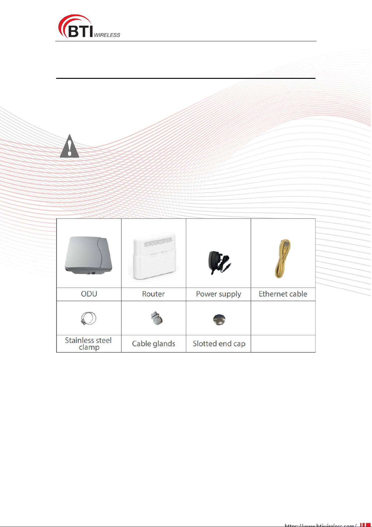
2 Packing List ............................................................................................................................. 5
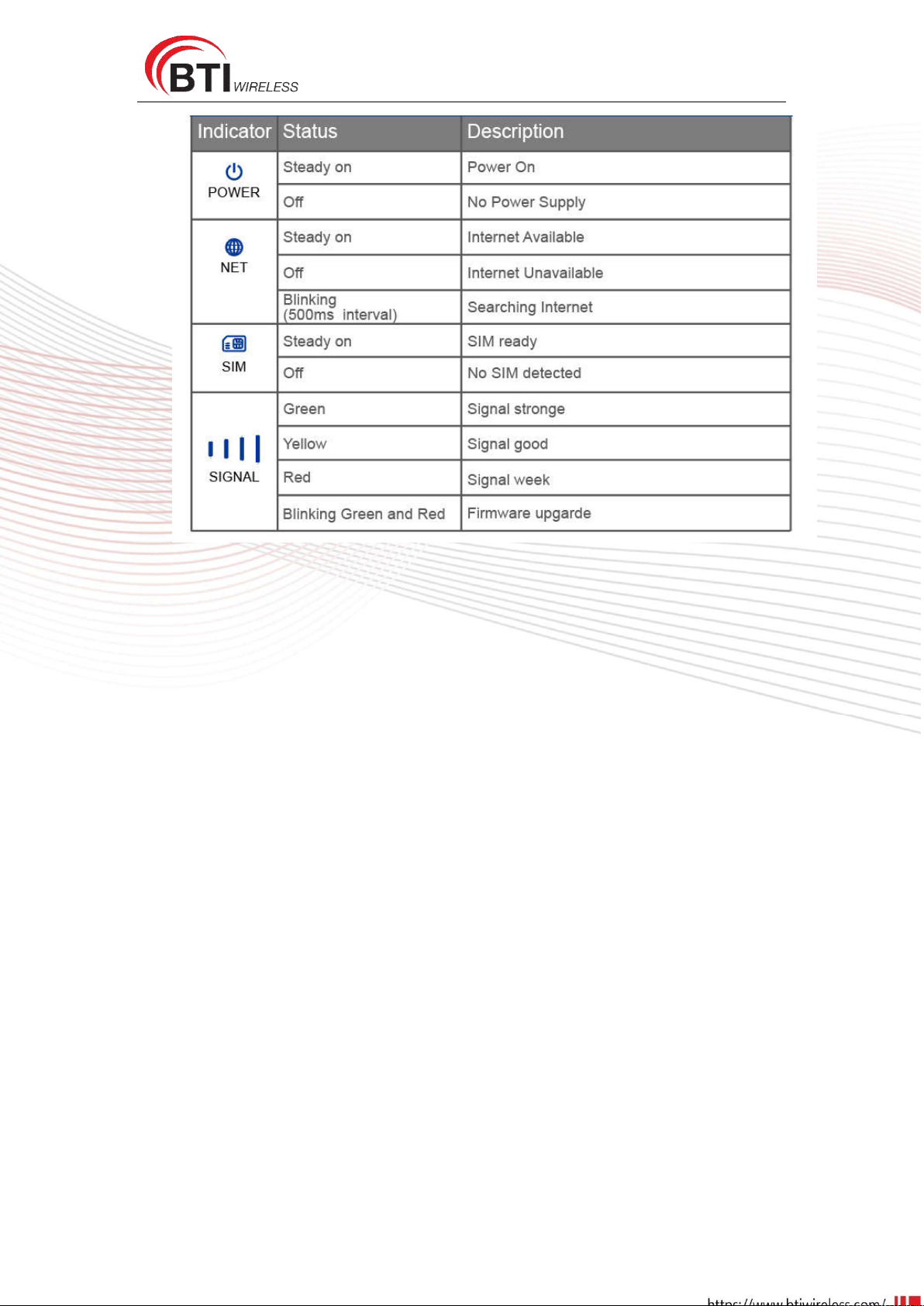
3.1 Panel of router ............................................................................................................ 6
3.2 Panel of ODU ............................................................................................................... 6
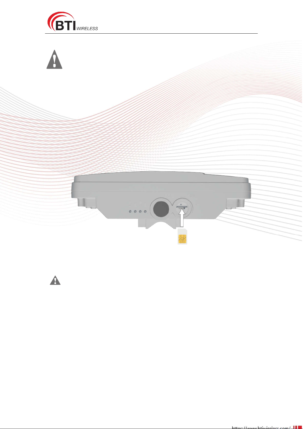
1 Install SIM Cards ..................................................................................................................... 8
2 Connect the Router to ODU ................................................................................................... 8
3 Mount the ODU ...................................................................................................................... 9
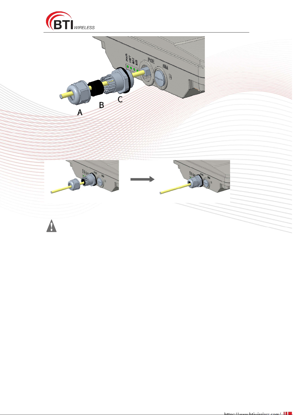
3.1 Cable glands Connection ............................................................................................. 9
3.2 Attach the Stainless-steel clamp to the Enclosure .................................................... 10
3.3 Wall or Pole Mounting .............................................................................................. 11
4 Choose Location ................................................................................................................... 12
5 Connect the Router .............................................................................................................. 13
CHAPTER 4: Software Features ....................................................................................................... 14
1 Getting Started ..................................................................................................................... 14
1.1 Welcome to the CPE .................................................................................................. 14
1.2 Computer Configuration Requirements .................................................................... 14
1.3 Login the Web Management Page ............................................................................ 15
2 Overview .............................................................................................................................. 17
2.1 Viewing Current Connection ..................................................................................... 17
2.2 Viewing WLAN Status ................................................................................................ 17
2.3 Viewing LTE Status ..................................................................................................... 18
2.4 Viewing WAN Status .................................................................................................. 18
3 Statistics ............................................................................................................................... 19
3.1 Viewing CPU Usage ................................................................................................... 19
3.2 Viewing Memory Usage ............................................................................................ 19
3.3 Viewing APN List ........................................................................................................ 20
3.4 Viewing Throughput Statistics ................................................................................... 20
3.5 Viewing Device List .................................................................................................... 20
4 Update .................................................................................................................................. 21
4.1 Version Manager ....................................................................................................... 21
4.2 Auto upgrade ............................................................................................................. 22
5 Settings ................................................................................................................................. 24
5.1 Viewing the Device Information ................................................................................ 24
5.2 Viewing Network ....................................................................................................... 25
5.3 Wi-Fi .......................................................................................................................... 36
5.4 Firewall ...................................................................................................................... 43
5.5 VPN ............................................................................................................................ 56

CP880+CR650
3
5.6 IPv6 ............................................................................................................................ 57
5.7 System ....................................................................................................................... 58
FAQs ................................................................................................................................................ 71
FCC Regulations: .............................................................................................................................. 72
FCC RF Radiation Exposure Statement ............................................................................................ 72

CP880+CR650
4
CHAPTER 1: Introduction
1 Introduction to Outdoor CPE with Router
Congratulations on your purchase of the CP880+CR650 (Outdoor 4G/LTE Router).
It includes two parts, an indoor unit and an outdoor unit. ODU can provide strong
accessibility to the LTE network, and has been designed to meet industrial-grade IP67
dustproof and waterproof standard. Router is a wireless device which can provide
ODU power supply. ODU with Router in combination is the ideal solution for
residential LTE network.
In addition to outdoor, it can be installed in environments such as: manufacturing
plants, industrial automation, stadiums, convention halls, stadium facilities, school
campuses or virtually any venue requiring a robust wireless solution.
2 Application Diagram

CP880+CR650
5
CHAPTER 2: Product Overview
1 Important Note for Using This Router
1, Do not remove, open or repair the case yourself. Contact with your Internet
Service Provider or have it repaired at a qualified service center.
2, Do not plug and unplug SIM card when device is power on.
3, It is mandatory to earth ground the CP880+CR650. Improper grounding not only
could damage the unit but also all equipments connected to it.
2 Packing List

CP880+CR650
6
3 Device Description
3.1 Panel of router
Router LED indicator operation
3.2 Panel of ODU
ODU LED indicator operation

CP880+CR650
7

CP880+CR650
8
CHAPTER 3: Hardware Installation
Please make sure that you are familiar with all accident prevention and
Safety procedures necessary for working at height and with electricity before start to
install the device.
DO NOT install the ODU during a lightning storm.
1 Install SIM Cards
Step1 Use a cross screwdriver to remove the SIM card cover.
Step2 Slide the SIM cards into the SIM card slots until they click into place. When the device is
powered on or reboots, it automatically connects to the network.
Step3 Re-attach the cover.
i
Make sure the ODU is turned off before you insert your SIM card. It is recommended to
NOT connect the PoE cable when you do this step. Otherwise, the SIM card may be
damaged.
2 Connect the Router to ODU
Place a CAT5e Ethernet cable from the location of your intended Router to the desired ODU
location.
The maximum distance of the CAT5e cable is limited to 50 meters. If you use cable extenders to
cover a greater distance, signal attenuation may occur.
If you intend to use cable clamps or other methods to secure the cable, do not tighten them until
you nish installing the Router and ODU.

CP880+CR650
9
Step 1 CAT5e cable to thread through the cable glands.
Step 2 Connect the end of the CAT5e Ethernet cable to the PoE port of the ODU.
Step 3 Wring the cable glands into ODU and seal tightly.
Make sure you have inserted the SIM card into the ODU.
3 Mount the ODU
See the installation instructions to mount the ODU correctly
3.1 Cable glands Connection
Cable glands are tools which are vital when terminating cables in harsh or hazardous settings. Its
role is to safely pass a tube, wire, or cable through an enclosure.
They also act as a seal, stopping exterior impurities from causing any damage to the electrical
system and the cable.
Below will help you make sure that the installation of your cable gland guarantees a reliable and
safe connection.
Step 1 Assemble M25 cable gland
Step 2 Unscrew the LAN (PoE) port and insert the supplied outdoor Ethernet cable (RJ-45)
through material A-C, and then connect the RJ-45 Ethernet cable into the LAN (PoE) port.

CP880+CR650
10
Step 3:
3.1: Insert B at the back end of C
3.2: keep B close to C
3.3: then tighten A
1, Care must be taken to prevent damage to the entry threads when organizing and
installing cable glands
2, Don’t install cable glands while the circuits are live.
3, Cable gland parts aren’t well-matched with those of any other manufacturer of cable
gland.
4, Take note that a cable gland isn’t a user-serviceable item.
5, Cable gland sealing rings are added in the cable gland if dispatched from the factory.
3.2 Attach the Stainless-steel clamp to the Enclosure
Using a screwdriver to loosen the metal hose clamps,through the terminal equipment mounting
hole, the metal hose clamps and the pole is fixed;

CP880+CR650
11
3.3 Wall or Pole Mounting
Mounting on Wall
(The built-in antenna is not recommended for wall hanging type, preferred to use Pole mounting
method, it can be convenient to adjust the direction of the antenna.)
When the ODU terminal is hanging on the wall, the specific mounting as follows:
When install ODU on the wall, fixed four screws spacing is 68mm on wall, then the terminal
equipment aligns the screws. Hang up and complete the installation.
Mounting on a Pole
Attach the Stainless-steel clamp to the pole which is smaller than 57mm.

CP880+CR650
12
4 Choose Location
The ODU can be mounted on an antenna pole or mast or on a wall using the supplied mounting
bracket.
Choose a mounting point that is sturdy enough to hold the ODU, even during high winds.
When choosing a location to install the ODU, please be noted that the ODU’s front panel
should point towards your service provider’s nearest base station. You do not need to be
able to see the base station from the ODU’s position. However, if you experience difficulties
with signal reception, a Line of Sight (LoS) connection may produce better results.
It is suggested that you transport the ODU to its intended installation location in its original
protective package.
To obtain the best radio signal level and connection quality, the CPE antenna should be aimed
towards the best eNB or BS directly. To search for the best eNB direction, the user can rotate the
CPE slowly and tilte CPE slightly to the best signal direction. The CPE radio signal strength level
can be observed from the RF LEDs mounted on the lower panel as shown below. The more LEDs
on, the better the signal strength.

CP880+CR650
13
5 Connect the Router
Place a CAT5e Ethernet cable (not included) from the location of your intended Router to the
desired PC location.
If you intend to use cable clamps or other methods to secure the cable, do not tighten them until
you nish installing the Router and ODU.

CP880+CR650
14
CHAPTER 4: Software Features
1 Getting Started
1.1 Welcome to the CPE
In this document, the LTE (Long Term Evolution) CPE (customer premises equipment) will be
replaced by the CPE. Carefully read the following safety symbols to help you use your CPE safely
and correctly:
Additional information
Optional methods or shortcuts for an action
Potential problems or conventions that need to be specified
1.2 Computer Configuration Requirements
For optimum performance, make sure your computer meets the following requirements.
Item Requirement
CPU Pentium 500 MHz or higher
Memory 128 MB RAM or higher
Hard disk 50 MB available space
Operating system
Microsoft: Windows XP, Windows Vista, or Windows 7
Mac:
Mac
OS
X
10.5
or
h
igher
Display resolution 1024 x 768 pixels or higher
Browser
Internet Explorer 7.0 or later
Firefox 3.6 or later
Opera 10 or later
Safari 5 or later
Chrome 9 or later

CP880+CR650
15
1.3 Login the Web Management Page
Launch web browser to login the web management page to configure and manage the CPE.
The following procedure describes how to use a computer running Windows XP and Internet
Explorer 7.0 to log in to the web management page of the CPE.
1. Connect the CPE properly.
2. Launch Internet Explorer, enter http://192.168.1.1 in the address bar, and press Enter. As
shown in Figure 1-1.
Figure 0-1
3. Enter the user name and password, and click Log In.
4. You can log in to the web management page after the password is verified. As shown in Figure
1-2.
Figure 0-2
The default user name and password are both admin. If you want to view or configure
the CPE more, you should use the super account to log in to the web management page.
The default super user name is superadmin, and the password is admin.
To protect your CPE from unauthorized access, change the password after your first
login.
The CPE supports diagnostic function. If you encounter problems, please contact
customer service for the specific using method.

CP880+CR650
16
To ensure your data safety, it is recommended that you turn on the firewall, and
conserve your login and FTP password carefully.

CP880+CR650
17
2 Overview
2.1 Viewing Current Connection
To view the current connection, perform the following steps:
1. Choose Overview;
2. In the Current Connection area, view the connection status, such as DL/UL Data Rate and
Online time. As shown in Figure 2-1.
Figure 0-3
2.2 Viewing WLAN Status
To view the WLAN status, perform the following steps:
1. Choose Overview;
2. In the WLAN Status area, view the information about WLAN status, Band, Chanel NO. and
Mode. As shown in Figure 2-2.
Figure 0-2

CP880+CR650
18
2.3 Viewing LTE Status
To view the LTE network status, perform the following steps:
1. Choose Overview;
2. In the LTE Status area, view the information about Connect status, Mode, Cell ID, Signal
quality and so on. As shown in Figure 2-3.
Figure 0-3
2.4 Viewing WAN Status
To view the WAN status, perform the following steps:
1. Choose Overview;
2. In the WAN Status area, view the information about Connect Mode, IP, Subnet Mask, DNS
Server and so on. As shown in Figure 2-4.
Figure 2-4

CP880+CR650
19
3 Statistics
3.1 Viewing CPU Usage
To view the CPU usage, perform the following steps:
1. Choose Statistics;
2. In the CPU Usage area, view the CPU usage information, such as Current CPU usage, Max
CPU usage, Min CPU usage. As shown in Figure 3-1.
Figure 3-1
3.2 Viewing Memory Usage
To view the memory usage, perform the following steps:
1. Choose Statistics;
2. In the Memory Usage area, view the memory usage information, such as Total memory,
Current memory usage, Max memory usage and Min memory usage. As shown in Figure
3-2.
Figure 3-2
This manual suits for next models
1
Table of contents