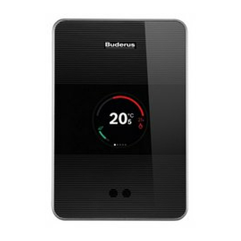
Buderus Logamatic BC10 Training manual

For users and heating
contractors
Read carefully before use
and service work.
Operating and service
instructions
Base controller
Logamatic
BC10
6 720 641 073 - 06/2009 GB

Contents
Base controller BC10 - Subject to technical modifications.
2
Contents
1 Explanation of symbols and
safety information . . . . . . . . . . . . . . . . . . . . . . . 3
1.1 Explanation of symbols . . . . . . . . . . . . . . . . . 3
1.2 Safety information . . . . . . . . . . . . . . . . . . . . . 3
2 Information about the product . . . . . . . . . . . . 4
2.1 EU Declaration of Conformity . . . . . . . . . . . 4
2.2 Correct use . . . . . . . . . . . . . . . . . . . . . . . . . . 4
2.3 Cleaning the base controller . . . . . . . . . . . . 4
3 Operating the base controller . . . . . . . . . . . . . 5
3.1 BC10 controls . . . . . . . . . . . . . . . . . . . . . . . 5
3.2 Switching ON and OFF . . . . . . . . . . . . . . . . 6
3.3 Selecting the maximum boiler water
temperature for heating mode . . . . . . . . . . 6
3.4 Selecting the set DHW temperature . . . . . 7
3.5 “Burner” LED (ON/OFF) . . . . . . . . . . . . . . . 7
3.6 Resetting faults . . . . . . . . . . . . . . . . . . . . . . . 8
3.7 Selecting manual mode . . . . . . . . . . . . . . . . 8
3.8 Displaying the status . . . . . . . . . . . . . . . . . . 9
4 For contractors . . . . . . . . . . . . . . . . . . . . . . . . . 10
4.1 Inserting the programming unit . . . . . . . . . 10
4.2 Removing the base controller . . . . . . . . . . 10
4.3 Starting operation under partial load . . . . 11
4.4 Carrying out a flue gas test . . . . . . . . . . . . 11
4.5 Setting parameters . . . . . . . . . . . . . . . . . . . 12
4.5.1 Limiting the heating load . . . . . . . . . . . . . . 12
4.5.2 Pump run-on time . . . . . . . . . . . . . . . . . . . . 12
4.5.3 DHW . . . . . . . . . . . . . . . . . . . . . . . . . . . . . . 12
4.5.4 Burner fan speed . . . . . . . . . . . . . . . . . . . . 12
4.6 Fault diagnosis . . . . . . . . . . . . . . . . . . . . . . 13
4.7 Resetting the service interval . . . . . . . . . . . 15
5 Environment/disposal . . . . . . . . . . . . . . . . . . . 16

1
Explanation of symbols and safety information
Base controller BC10 - Subject to technical modifications. 3
1 Explanation of symbols and safety information
1.1 Explanation of symbols
Warning symbols
Signal words indicate the seriousness of the hazard in
terms of the consequences of not following the safety
instructions.
•NOTICE indicates possible damage to property or
equipment, but where there is no risk of injury.
•CAUTION indicates possible injury.
•WARNING indicates possible severe injury.
•DANGER indicates possible risk to life.
Important information
Additional symbols
1.2 Safety information
Installation and commissioning
BObserve these operating and service instructions to
ensure the appliance functions correctly.
BRead and observe the safety information and code of
conduct.
BInstallation and commissioning must only be carried
out by qualified and trained installers.
Usage
BAlways use this appliance correctly and in conjunction
with the specified control systems.
BObserve all country-specific regulations and standards
during installation and operation.
BUse only original spare parts.
Risk to life from electric shock
BEnsure that electrical work is only carried out by an
authorised electrician.
BFollow the connection diagram.
BBefore starting electrical work, isolate all poles of the
system and secure against unintentional reconnection.
BEnsure the system has been isolated from the supply.
BNever install this appliance in wet rooms.
Risk of scalding
BEnsure that a thermostatically controlled mixer is
installed to limit the draw-off temperature to a maximum
of 50 °C.
System damage through frost
The heating system can freeze up in cold weather if
switched off or locked out through a fault condition:
BLeave the heating system permanently switched on.
BEnable frost protection.
BIn case of faults: immediately remedy the fault.
Risk of damage due to operator error
Operator errors can result in injury and damage to
property.
BEnsure that children never operate this appliance
unsupervised or play with it.
BEnsure that only personnel who can operate this
appliance correctly have access to it.
Safety instructions in this document are
framed and identified by a warning triangle
which is printed on a grey background.
Electrical hazards are identified by a lightning
symbol surrounded by a warning triangle.
Notes contain important information in cases
where there is no risk of personal injury or
material losses and are identified by the
symbol shown on the left. They are bordered
by horizontal lines above and below the text.
Symbol Meaning
Ba step in an action sequence
Æa reference to a related part in the
document or to other related documents
• a list entry
–a list entry (second level)
Tab. 1

2Information about the product
Base controller BC10 - Subject to technical modifications.
4
2 Information about the product
The BC10 base controller enables the operation of the
standard functions of Buderus heating systems equipped
with the Energy Management System (EMS)1) directly at
the boiler.
Various programming units can be used in conjunction
with the base controller, e.g. for convenient regulation of
room and DHW temperature or for using heating
programs.
The BC10 base controller must be fitted to the boiler
itself.
2.1 EU Declaration of Conformity
The design and operation of this product conform to
European Directives and the supplementary national
requirements. Its conformity is demonstrated by the
CE designation. You can call up the Declaration of
Conformity for this product at the internet at
www.buderus.de/konfo or request it from your local
Buderus sales office.
2.2 Correct use
The BC10 base controller must only be used for the
operation and control of Buderus heating systems.
BAlways use this appliance correctly and in conjunction
with the specified control systems.
BObserve all country-specific regulations and standards
during installation and operation.
2.3 Cleaning the base controller
BOnly clean the base controller with a damp cloth and a
mild detergent.
1) The Energy Management System (EMS) controls and monitors the
heating system.

3
Operating the base controller
Base controller BC10 - Subject to technical modifications. 5
3 Operating the base controller
The BC10 base controller enables the operation of the
standard heating system functions. For this, it makes the
various functions available, including:
• Switching the heating system ON and OFF
• DHW temperature default and maximum boiler water
temperature in heating mode
• Status display
3.1 BC10 controls
Fig. 1 Controls
1ON/OFF switch
2Set DHW rotary selector
3DHW heating LED
4Status display
5Rotary selector for maximum boiler water temperature in
heating mode
6DHW demand LED
7Slot for a programming unit, e.g. RC3x or fascia
8Burner (ON/OFF) LED
9Connection socket for diagnostic plug
10 Status display key
11 “Chimney Sweep button” for flue gas test and
manual mode
12 Reset
12 10
6720614021-003.1TD
2 4 5
12 10 8
11 9 71
36

3Operating the base controller
Base controller BC10 - Subject to technical modifications.
6
3.2 Switching ON and OFF
BTo switch ON, set the ON/OFF switch [1] to “1”.
This switches ON the entire heating system. The status
display on the base controller illuminates and shows
the current boiler water temperature in °C.
BTo switch OFF, set the ON/OFF switch [1] to “0”.
Fig. 2 Switching the base controller ON and OFF
3.3 Selecting the maximum boiler water
temperature for heating mode
At the “maximum boiler water temperature” rotary
selector [1], you can set the upper limit temperature for
the boiler water in heating mode. This limit will not apply
to DHW heating.
Fig. 3 Rotary selector for maximum boiler water
temperature in heating mode
DANGER: Risk to life from electric shock!
BIf a risk becomes apparent, isolate all
poles of the heating system or isolate it
from the power supply via circuit breaker/
fuse.
Explanation
0Heating operation is switched OFF (poss. only
DHW operation).
30 – 901)
1) In conjunction with the RC3x programming unit, always select
“Aut”.
The temperature is set permanently at the BC10
and cannot be changed at the programming unit.2)
2) All programming unit control functions (e.g. heating program,
summer/winter changeover) remain enabled.
Aut The temperature is established automatically with a
programming unit (e.g. RC3x) using the heating
curve. If no programming unit is connected, the
maximum boiler water temperature is 90 °C.2)
Tab. 2 Settings at the “maximum boiler water
temperature” rotary selector
If central heating is switched on and heat is
demanded, then the LED below the rotary
selector illuminates.

3
Operating the base controller
Base controller BC10 - Subject to technical modifications. 7
3.4 Selecting the set DHW temperature
The “set DHW” rotary selector [1] enables you to specify
the required DHW temperature in the DHW cylinder.
Fig. 4 Set DHW rotary selector
3.5 “Burner” LED (ON/OFF)
The LED signals the burner status.
Fig. 5 “Burner” LED (ON/OFF)
DHW is always heated at the maximum
permissible boiler water temperature.
Explanation
0No supply to radiators (exclusively DHW heating).
Eco 1)
1) This function is optimised for appliances with integral DHW
heating (combi boilers, e.g. GB132T). If a programming unit is
installed (otherwise direct adjustment at the BC10), we
recommend the “Aut” setting in conjunction with other boilers.
Economy mode 2), DHW temperature 60 °C
If the temperature has dropped significantly, DHW is
first heated to 60 °C again. This reduces the number
of burner starts and saves energy. However, the
water may be somewhat cooler in the first few
moments.
2) The heating program (time switch) of the programming unit
remains enabled, consequently no DHW is produced during
night operation.
30 – 60 The temperature is set at the BC10 and can then no
longer be adjusted with the programming unit.2)
Aut The temperature is set at the programming unit
(e.g. RC3x).
60 °C is set as the DHW temperature if no
programming unit is connected.
Tab. 3 Settings at the “set DHW” rotary selector
The LED below the rotary selector illuminates
whilst the DHW in the DHW cylinder is being
heated to the preselected set temperature.
Status Explanation
ON Burner operational. Boiler water is heated.
OFF Burner off. The boiler water has reached the
required temperature level or
there is no heat demand.
Tab. 4 Meaning of the LED

3Operating the base controller
Base controller BC10 - Subject to technical modifications.
8
3.6 Resetting faults
You can reset a fault by pressing “Reset” if the burner
(combustion controller) is in a fault state. This is only
required for locking errors. Blocking errors are reset
automatically when their cause is removed.
BTo reset the error, press “Reset”.
The display shows rE whilst the system is being reset.
Fig. 6 “Reset” button
3.7 Selecting manual mode
In manual mode, the heating system can be operated
independently of a programming unit. The boiler will
operate with the boiler water temperature selected on the
r.h. rotary selector as the set temperature.
In manual mode, the decimal point on the display flashes.
BHold down d(“Chimney Sweep”) for at least
8 seconds until the decimal point flashes in the
display.
BTurn the r.h. rotary selector to select the set boiler
water temperature (boiler flow temperature).
BTo terminate manual mode, press dagain.
Fig. 7 Selecting manual mode
Floorstanding boilers:
If the fault cannot be reset, either the boiler
water temperature is still too high or the
digital SAFe combustion controller must be
reset first.
If the burner fault recurs after the reset,
contact your heating contractor.
Manual mode terminates after the power has
been switched off or if it has failed.
BAfter switching on, re-activate manual
mode so that the heating system keeps
running (especially if there is a risk of
frost).

3
Operating the base controller
Base controller BC10 - Subject to technical modifications. 9
3.8 Displaying the status
The BC10 base controller display indicates the status of
the heating system.
In case of errors, the status display immediately indicates
the relevant fault or warning. If a error occurs, contact your
heating contractor and advise them of the service and
fault codes.
The warnings and errors depend on the boiler used. For
further information on the codes please refer to the
description of the boiler concerned. Locking errors cause
the status display to flash.
Initial status:
In the standard operating state, the current boiler water
temperature is displayed, e.g. 60 °C.
BIf the display indicates a fault or warning, e.g. H7 or 2E
(ÆChapter 4.6).
Further status displays:
BTo change to the next status display, press e(“status
display”).
P1.2: Current operating pressure (subject to boiler
type only if a pressure sensor is installed).
BTo change to the next status display, press eagain.
0Y: Operating status (display code).
BTo change to the next status display, press eagain.
60: The boiler water temperature is displayed again.
Fig. 8 Status display

4For contractors
Base controller BC10 - Subject to technical modifications.
10
4 For contractors
4.1 Inserting the programming unit
BDisconnect the heating system from the mains power
supply.
BOnly if gas is used as fuel: close the main gas tap.
The programming unit can either be installed in a living
area or at the BC10 base controller.
1. Push the release tabs at the top and bottom of the
fascia simultaneously.
2. Remove the fascia from the base plate by pulling in the
direction of the arrow.
Fig. 9 Removing the fascia
3. Hook the programming unit in the direction of the
arrows into the top edge of the base plate.
4. Push the programming unit lightly upwards until it
snaps into place.
Fig. 10 Hooking the RC3x programming unit into place
4.2 Removing the base controller
1. Undo screws at the cover of the MC10 control unit.
2. Lift off the cover.
Fig. 11 Removing the cover
3. Undo the electrical plug-in connections from the
control unit.
4. Remove the base controller from the control unit.
Fig. 12 Removing the base controller
Generally installation and service work must
only be carried out by a heating contractor.
3.
4.
DANGER: Risk to life from electric shock!
BEnsure that electrical work is only carried
out by an authorised electrician.
BIsolate the heating system from the power
supply before opening the control unit.
BSafeguard the heating system from
unintentional reconnection.

4
For contractors
Base controller BC10 - Subject to technical modifications. 11
4.3 Starting operation under partial
load
During the flue gas test you can operate the boiler at a
reduced output (set boiler temperature), e.g. when
adjusting a gas valve. This reduction only applies during
the flue gas test.
BHold down d(“Chimney Sweep”) for at least
2 seconds until the decimal point illuminates in the
display.
BTo start partial load operation, simultaneously press d
and efor five seconds.
BTo reduce the rated boiler output in percent, press
“Reset”.
Example L50.: Boiler output reduced to 50 % of rated
boiler output.
BTo increase the boiler output by percent, press d
again.
Fig. 13 Starting operation under partial load
4.4 Carrying out a flue gas test
The flue gas inspector uses the dkey (“Chimney
Sweep”) for the flue gas test.
The heating system operates with a higher flow
temperature for 30 minutes. During the flue gas test, the
decimal point on the display illuminates.
BHold down dfor at least 2 seconds until the decimal
point illuminates in the display.
Fig. 14 Carrying out a flue gas test
BCarry out a flue gas test.
BTo terminate the flue gas test, press dagain.
Operation under partial load is only possible
with two-stage or modulating burners. The
lowest possible setting is burner-dependent.

4For contractors
Base controller BC10 - Subject to technical modifications.
12
4.5 Setting parameters
Operating the programming mode
BTo enter the programming mode, simultaneously hold
down d(“Chimney Sweep”) and e(“status display”)
for five seconds.
BTo change to the next parameter, press eagain.
BTo reduce the parameter value ( – ), press “Reset”.
BTo increase the parameter value (+), press dagain.
Programming mode is terminated if no key is pressed for
five minutes.
Fig. 15 Setting parameters
4.5.1 Limiting the heating load
Parameter L-- is used to reduce the burner output for
heating mode (only with two-stage or modulating
burners). This extends the burner runtime and reduces the
number of burner starts. Subject to the heating system
design, this will save energy.
This parameter can be recognised by the letter “L”.
The L-- setting means that the rated boiler output is not
restricted.
xx The lowest possible setting is burner-dependent.
4.5.2 Pump run-on time
With parameter F5, the boiler pump run-on time can be
set in minutes.
This parameter can be recognised by the letter “F”.
The setting F1d means the boiler pump runs constantly.
4.5.3 DHW
Parameter C0 is used to determine whether DHW is to be
heated by the boiler.
This parameter can be recognised by the letter “C”.
Setting 0also disables frost protection for the DHW lines.
4.5.4 Burner fan speed
Parameters 1. and 2. enable a correction of the
combustion air supply. With this setting, the burner can
be adjusted during commissioning.
Input range Standard setting
Heating load limit L xx – 99 %
100 % (L--)
100 % (L--)
If you reduce the burner output, the heating
system does not heat up as quickly. If you
reduce the burner output too much, the
temperature in the building may be too low
for comfort.
BEnsure that the selected value is higher
than the maximum burner output required
to heat the building.
Input range Standard setting
Pump run-on time F 1 – 60 min
24 h (F1d)
5 min
Input range Standard setting
DHW C 0 (no DHW)
1(DHW)
boiler-dependent
The parameters are only displayed on boilers
with a digital SAFe combustion controller
and on burners that allow this correction to
be carried out electronically.
Input range Standard setting
Air correction
stage 1: 1.
– 9 – +9 burner-dependent
Air correction
stage 1: 2.
– 9 – +9 burner-dependent

4
For contractors
Base controller BC10 - Subject to technical modifications. 13
4.6 Fault diagnosis
The BC10 base controller display indicates the status of
the heating system.
In case of errors, the status display immediately indicates
the relevant fault or warning. If an error occurs, contact
your heating contractor and advise them of the service
and fault codes.
The warnings and errors depend on the boiler used.
For further information on the codes please refer to the
description of the boiler concerned. Locking errors cause
the status display to flash.
BTo change between the status displays, press eagain.
Fig. 16 Status display
Subject to operating state, the following status displays can be displayed:
Display (examples) Value range Explanation Operating state/remedy
601) Figure 0 ... 100 Current boiler water temperature Standard operating state
P1.5 > P1.0 Current operating pressure 2)
HAH Service interval according to hours run
or date has been enabled.
– H Operating message:
current EMS state
P0.8/H71) (alternately) P0.2 ... P1.0 Warning2):
Operating pressure too low
(between 0.2 and 1.0 bar)
Warning
BTop up the heating system.
If the operating pressure is greater than
1.0 bar, the display changes to the
standard display for standard operation
after 10 minutes.
– H Operating message:
current EMS state
60 Figure 0 ... 100 Current boiler water temperature
P0.8 P0.2 ... P1.0 Current operating pressure
(only with a digital pressure sensor)2)
P0.11) (flashing) < P0.2 Error2):
Operating pressure much too low
(< 0.2 bar).
Error
Operating pressure much too low. Burner
and boiler pump are off. Frost protection
enabled down to 0.1 bar.
BTop up the heating system.
If the operating pressure is greater than
1.0 bar, the display changes to the
standard display for standard operation
after 10 minutes.
BClear the error with “Reset.”
207 Figure > 200 Fault code
60 Figure 0 ...100 Current boiler water temperature
P0.1 < P0.2 Current operating pressure 2)
Tab. 5 Possible status displays

4For contractors
Base controller BC10 - Subject to technical modifications.
14
H81) H00 ... H99 Service: Service required Service message (maintenance
message)
BContact your heating contractor to have
a service carried out.
Explanation of the service codes (Æservice
instructions of the relevant boiler).
– H Operating message:
current EMS state
60 Figure 0 ... 100 Current boiler water temperature
P1.5 > P1.0 Current operating pressure2)
2E1) (flashes
intermittently)
Combination
of letters
and numbers
Service code Error
BNotify your heating contractor and, if
possible, advise them of the service and
fault codes.
BIf the display flashes (locking error),
press reset to reset the error. If the
display is not flashing (blocking error),
the error will be reset automatically when
its cause has been removed.
BIf a blocking error has been present for
a long time, please notify your heating
contractor.
207 Figure > 200 Fault code
60 Figure 0 ... 100 Current boiler water temperature
P1.5 > P1.0 Current operating pressure 2)
HAH Service interval according to hours run
or date has been enabled.
A121) A00 ... A99 Service code Plant error
BNotify your heating contractor and,
if possible, advise them of the service
and fault codes.
Plant errors are heating system faults that
will not impair the burner operation.
816 Figure > 800 Fault code
– H Operating message:
current EMS state
60 Figure 0 ... 100 Current boiler water temperature
P1.5 > P1.0 Current operating pressure 2)
HAH Service interval according to hours run
or date has been enabled.
–
(flashing) Error
No communication between
programming module and the
combustion controller.
Error
BNotify your heating contractor.
BHeating contractor: check the
connections on both devices and the
communication cables.
1) Standard display for this operating state. This display will be shown after 5 minutes if no keys are pressed.
2) The boiler must be equipped with a digital pressure sensor to capture the operating pressure.
Display (examples) Value range Explanation Operating state/remedy
Tab. 5 Possible status displays

4
For contractors
Base controller BC10 - Subject to technical modifications. 15
4.7 Resetting the service interval
The programming unit (e.g. RC3x) can be used to set a
timed service interval for boilers with digital SAFe
combustion controller (defined in terms of hours run or a
fixed date).
When the service interval has expired, the display will
show H3 or H8 (ÆTab. 5, page 13). After carrying out
the service, reset the service interval as follows:
BPress “Reset” until HrE is shown in the status display.
The service interval is reset and restarts with the set
number of hours. With setting “MAINTENANCE ACC
TO DATE”, the next maintenance message will be
displayed precisely one year later.
Maintenance before expiry of the service interval
BPress “status display” several times until HAH (service
interval enabled) appears on the display.
No service interval is enabled (i.e. resetting is not
possible) if HAH does not appear even after pressing
the key several times.
BPress “Reset” until HrE is shown in the status display.
This resets the service interval, which starts again.
Fig. 17 Status display

5Environment/disposal
Base controller BC10 - Subject to technical modifications.
16
5 Environment/disposal
Environmental protection is one of the fundamental
company policies of the Bosch Group.
We regard quality of performance, economy and
environmental protection as equal objectives. All
legislation pertaining to the environment is strictly
observed. We use the best possible technologies and
materials to protect the environment, subject to relevant
economical aspects.
Packaging
Where packaging is concerned, we participate in country-
specific recycling processes that ensure optimum
recycling. All packaging materials are environmentally
compatible and can be reused.
Old appliances
Old appliances contain materials that should be recycled.
The assemblies are easily separated and are clearly
marked. This allows the various assemblies to be
appropriately sorted for recycling or disposal.

5
Base controller BC10 - Subject to technical modifications. 17
Notes

5
Base controller BC10 - Subject to technical modifications.
18
Notes

5
Base controller BC10 - Subject to technical modifications. 19
Notes

Buderus
Cotswold Way, Warndon, Worcester WR4 9SW
Customer service: 0844 892 9700
echnical support: 0844 892 3004
Fax: 01905 753130
www.buderus.co.uk
In the UK and IE, Buderus is a brand name of
Bosch hermotechnology Ltd.
Table of contents
Other Buderus Controllers manuals
Popular Controllers manuals by other brands

CBE
CBE PRM330 user manual

Net Safety
Net Safety MAN-0069 user manual

Franke
Franke ZAQUA005 Installation and operating instructions

Kubler
Kubler CODIX 565 user manual

Sonance
Sonance One Zone Amplified Connecting Block ACB1 installation instructions

Thermo Scientific
Thermo Scientific 200L instruction manual